|
|
|
|
|
|
| |
| |
|
|
|
|
| |
| |
|
|
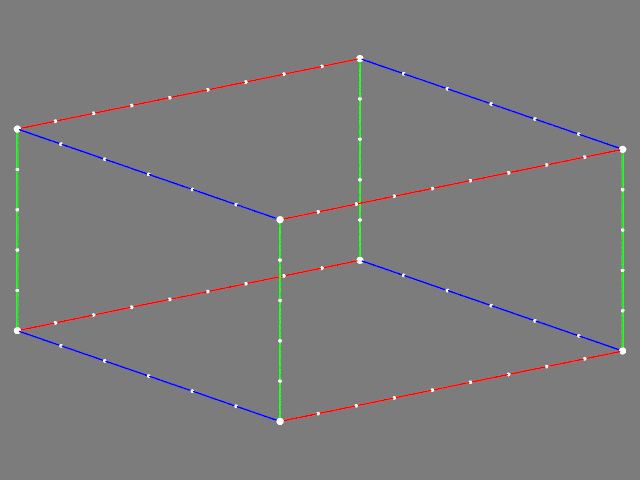
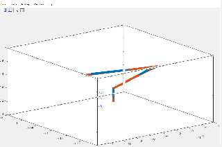
Hello everyone,
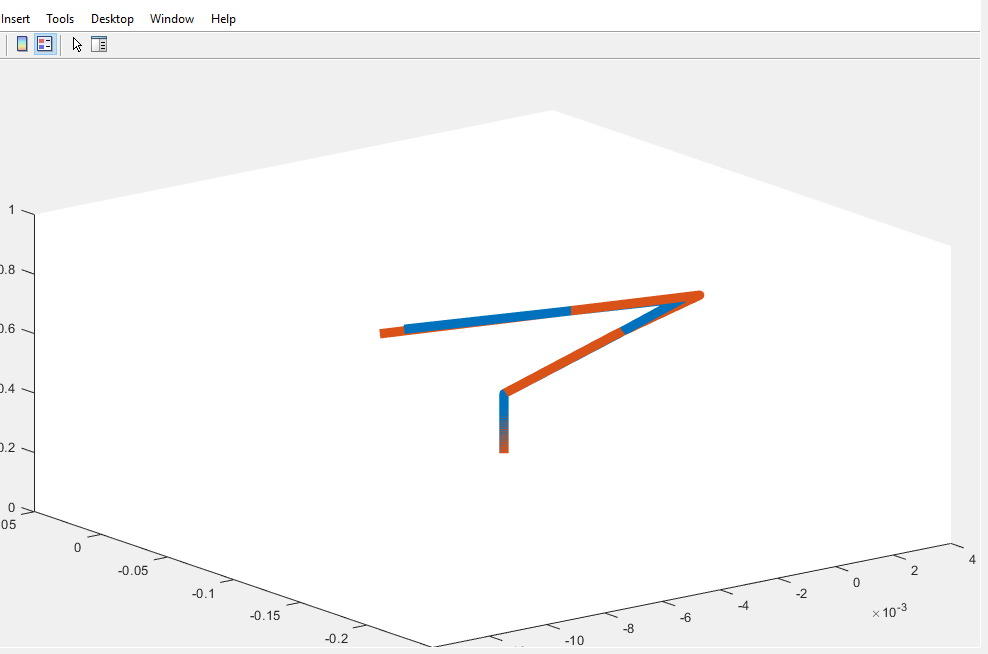
I created a spline object using the following code, but I could not get the
proper camera position. I was wondering if there is some systematic way to
figure out the camera position, and angle and look at vectors for a given shape.
Or is it just trial and error? Can someone please help me to get the proper
camera setup so as to obtain the figure attached:
// code used
#include"colors.inc"
camera {
location <-0.0872 , -1.8850 , 4.8301 >*3.5
look_at <0,0,0> }
light_source {
<4,6,-10>
color rgb<1,1,1> }
background {
color rgb<0.5,0.5,0.5> }
sphere_sweep {
b_spline
6,
<0,0,-20>,0.1,
<2.583e-09,-2.7093e-08,3>,0.1,
<0.075646,-0.91834,8.9288>,0.1,
<0.076898,-2.3756,14.7492>,0.1,
<-0.15231,-4.2038,20.4593>,0.1,
<-0.15231,-4.2038,20.4593>,0.1
tolerance 0.1
texture{ pigment{ color rgb<0.69,0.99,0.15>}
finish { phong 1
ambient 0.3
}
}
scale<2,2,0.35> rotate<-90,0,0> translate<0,-2,3>
}
Post a reply to this message
Attachments:
Download 'screenshot 2022-05-22 180728.png' (23 KB)
Preview of image 'screenshot 2022-05-22 180728.png'
|
|
| |
| |
|
|
|
|
| |
| |
|
|
hi,
"Aj" <nomail@nomail> wrote:
> Hello everyone,
>
> I created a spline object using the following code, but I could not get the
> proper camera position. I was wondering if there is some systematic way to
> figure out the camera position, and angle and look at vectors for a given shape.
> Or is it just trial and error?
the latter, I guess, based on knowledge of object's approximate location +
dimensions. hope to find time to try your code, but for a simple, recent
animation I needed to move the camera back to accommodate the object growing
larger. have a look at the camera in 'ulam2.pov' (at end of file), its location
is updated in every frame. while different in detail, perhaps it can serve as
"food for thought". hth.
<http://news.povray.org/povray.binaries.images/attachment/%3Cweb.6240f11b8a870000fc0c8de6cde94f1%40news.povray.org%3E/u
lam2.zip>
regards, jr.
Post a reply to this message
|
|
| |
| |
|
|
|
|
| |
| |
|
|
Take a look at the 'Spline_Trans' macro in POV-ray's transforms.inc file, and
the example camera scene called 'splinefollow.pov' in
scenes/animations/splinefollow.
The idea is that you pre-#declare your spline, stick that into the Spline_Trans
macro, then use the macro as your animated camera position. (No need to make an
actual spline object.) Here is the example as given in the 'splinefollow.pov'
scene file...
camera {
location 0
look_at z
translate <0,0.4,0.4> // [probably optional]
Spline_Trans (MySpline, clock*11, y, 0.5, 0.5)
}
By the way, a spline's 'index list' is not confined to the range of 0.0-1.0
(although that's very convenient when using the 'clock' value for the animated
camera movement.) For some scenes, I like to use frame_numbers for my spline
points instead, as it is more intuitive for me. For example, running a 200-frame
animation...
spline{
.....
1, <...>
37, <...>
135, <...>
200, <...>
}
Then the Spline_Trans macro would be used like this:
Spline_Trans (MySpline, frame_number, y, 0.5, 0.5)
Post a reply to this message
|
|
| |
| |
|
|
|
|
| |
| |
|
|
"Kenneth" <kdw### [at] gmail com> wrote:
> Take a look at the 'Spline_Trans' macro in POV-ray's transforms.inc file, and
> the example camera scene called 'splinefollow.pov' in
> scenes/animations/splinefollow.
>
Sorry, I assumed that you wanted your camera to *follow* the spline shape,
during an animation. (I also forgot to mention that you would need to #include
"transforms.inc" in your scene.) com> wrote:
> Take a look at the 'Spline_Trans' macro in POV-ray's transforms.inc file, and
> the example camera scene called 'splinefollow.pov' in
> scenes/animations/splinefollow.
>
Sorry, I assumed that you wanted your camera to *follow* the spline shape,
during an animation. (I also forgot to mention that you would need to #include
"transforms.inc" in your scene.)
Post a reply to this message
|
|
| |
| |
|
|
|
|
| |
| |
|
|
"Aj" <nomail@nomail> wrote:
> Hello everyone,
>
> I created a spline object using the following code, but I could not get the
> proper camera position. I was wondering if there is some systematic way to
> figure out the camera position, and angle and look at vectors for a given shape.
Yours might be easier, given that you have the grid locations on axes to guide
you.
Try imagining how the image you posted could be rotated in reverse to straighten
the axes in the camera frustrum, and use those transforms on the object.
The actual camera position might be a bit of trial and error to get exactly
right.
The look_at position might be obtained by extrapolating the x/z grid ticks and
applying that inverse rotate transform.
Maybe Francois LeCoat has a clever solution, as this seems right up his alley,
or TOK has some words/code lines of wisdom to offer.
Post a reply to this message
|
|
| |
| |
|
|
|
|
| |
| |
|
|
On 23/05/2022 1:08 am, Aj wrote:
> Hello everyone,
>
> I created a spline object using the following code, but I could not get the
> proper camera position. I was wondering if there is some systematic way to
> figure out the camera position, and angle and look at vectors for a given shape.
> Or is it just trial and error? Can someone please help me to get the proper
> camera setup so as to obtain the figure attached:
>
>
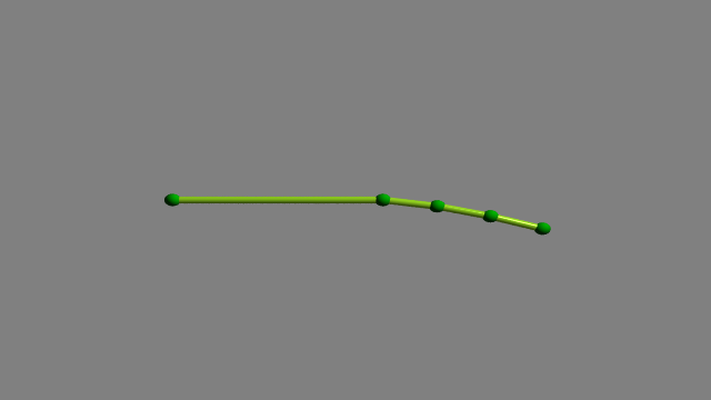
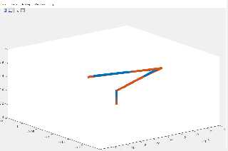
The points in your sphere_sweep don't plot the figure in the screen
shot, the points form a more or less straight line in the z direction.
(1.png) (Points 5 & 6 are the same.)
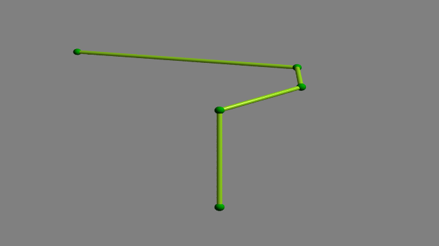
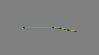
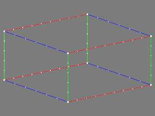
Looking again at the screen shot, I notice that the 3 axes are at
different scales. If I apply scaling and rotation to the points I can
get something like your figure. Scale = <200,10,1> rotate<0,90,0> (2.png)
Note that I have moved the camera to <0,0,-200>, looking at <0,0,0>. I
find it easier to keep track of x,y,z if the camera is in the minus z
position.
If you want a point for the camera to look at, you can find the mean
center of your plot thus:
#declare Thing_max = max_extent(Thing);
#declare Thing_min = min_extent(Thing);
#declare Thing_centre = (max_extent(Thing) + min_extent(Thing))/2;
(Red sphere)
---------------------------------------------------------------
#include"colors.inc"
camera {
//location <-0.0872 , -1.8850 , 4.8301 >*3.5
location <0,0,-200>
look_at <0,0,0>
angle 22
}
light_source { <100,100,-100> color rgb<1,1,1> }
background {color rgb<0.5,0.5,0.5> }
#declare Scale = <200,10,1>;
//#declare Scale = <1,1,1>;
#declare P01 = Scale*< 0, 0, -20>;
#declare P02 = Scale*< 2.583e-09,-2.7093e-08, 3>;
#declare P03 = Scale*< 0.075646, -0.91834, 8.9288>;
#declare P04 = Scale*< 0.076898, -2.3756, 14.7492>;
#declare P05 = Scale*<-0.15231, -4.2038, 20.4593>;
#declare P06 = Scale*<-0.15231, -4.2038, 20.4593>;
#declare Thing = union{
sphere{P01 0.9 pigment{rgb<0,1,0>}}
sphere{P02 0.9 pigment{rgb<0,1,0>}}
sphere{P03 0.9 pigment{rgb<0,1,0>}}
sphere{P04 0.9 pigment{rgb<0,1,0>}}
sphere{P05 0.9 pigment{rgb<0,1,0>}}
sphere{P06 0.5 pigment{rgb<0,1,0>}}
sphere_sweep {
//b_spline
linear_spline
6,
P01,0.5,
P02,0.5,
P03,0.5,
P04,0.5,
P05,0.5,
P06,0.5
tolerance 0.1
texture{ pigment{ color rgb<0.69,0.99,0.15>}
finish { phong 1
ambient 0.3
}
}
//scale<2,2,0.35> rotate<-90,0,0> translate<0,-2,3>
}
//rotate<0,90,0>
rotate<-90,0,0>
}
#declare Thing_max = max_extent(Thing);
#declare Thing_min = min_extent(Thing);
#declare Thing_centre = (max_extent(Thing) + min_extent(Thing))/2;
sphere{Thing_centre, 1.5 pigment{rgb<1,0,0>} rotate<0,360*clock,0>}
//box{Thing_min, Thing_max pigment{rgbt<1,0,0,0.8>}
rotate<0,360*clock,0>}
object{Thing rotate<0,360*clock,0>}
Post a reply to this message
Attachments:
Download '1.png' (7 KB)
Download '2.png' (10 KB)
Preview of image '1.png'
Preview of image '2.png'
|
|
| |
| |
|
|
|
|
| |
| |
|
|
"Bald Eagle" <cre### [at] netscapenet> wrote:
> "Aj" <nomail@nomail> wrote:
> > Hello everyone,
> >
> > I created a spline object using the following code, but I could not get the
> > proper camera position. I was wondering if there is some systematic way to
> > figure out the camera position, and angle and look at vectors for a given shape.
>
> Yours might be easier, given that you have the grid locations on axes to guide
> you.
>
> Try imagining how the image you posted could be rotated in reverse to straighten
> the axes in the camera frustrum, and use those transforms on the object.
> The actual camera position might be a bit of trial and error to get exactly
> right.
>
> The look_at position might be obtained by extrapolating the x/z grid ticks and
> applying that inverse rotate transform.
>
> Maybe Francois LeCoat has a clever solution, as this seems right up his alley,
> or TOK has some words/code lines of wisdom to offer.
Hehe, there you tempted me to have a look at this.
I opened the screenshot in gimp and copied the 3 axes around to check if the
camera used could be a orthographic camera. It seems so.
See the attached image.
And here's some code ;-)
// ===== 1 ======= 2 ======= 3 ======= 4 ======= 5 ======= 6 ======= 7
// Render options: +w640 +h480 +a0.3
#version 3.7;
global_settings { assumed_gamma 1.0 }
#include "colors.inc"
default {
texture {
pigment { color White }
finish {
diffuse 0
emission color White
}
}
}
// ===== 1 ======= 2 ======= 3 ======= 4 ======= 5 ======= 6 ======= 7
// Extreme values on the axes
#declare XN0 = -14.00; // *1e-3
#declare XP0 = +4.00; // *1e-3
#declare YN0 = 0.00; // *1e-3 ?
#declare YP0 = +1.00; // *1e-3 ?
#declare ZN0 = -0.25; // *1e-3 ?
#declare ZP0 = +0.05; // *1e-3 ?
// Divisions on the axes
#declare DivX0 = 2.00; // *1e-3
#declare DivY0 = 0.20; // *1e-3 ?
#declare DivZ0 = 0.05; // *1e-3 ?
// Number of divisions from the center of
// each axis to the axis endpoints
#declare XN1 = -4.5;
#declare XP1 = +4.5;
#declare YN1 = -2.5;
#declare YP1 = +2.5;
#declare ZN1 = -3.0;
#declare ZP1 = +3.0;
// These were found by trail and error
#declare ScaleX = 1.10;
#declare ScaleY = 0.96;
#declare ScaleZ = 1.64;
#declare FnX =
function(x) {
ScaleX*(XN1 + (x - XN0)/(XP0 - XN0)*(XP1 - XN1))
}
;
#declare FnY =
function(y) {
ScaleY*(YN1 + (y - YN0)/(YP0 - YN0)*(YP1 - YN1))
}
;
#declare FnZ =
function(z) {
ScaleZ*(ZN1 + (z - ZN0)/(ZP0 - ZN0)*(ZP1 - ZN1))
}
;
#declare XN2 = FnX(XN0);
#declare XP2 = FnX(XP0);
#declare YN2 = FnY(YN0);
#declare YP2 = FnY(YP0);
#declare ZN2 = FnZ(ZN0);
#declare ZP2 = FnZ(ZP0);
#declare pNNN = <XN2, YN2, ZN2>;
#declare pPNN = <XP2, YN2, ZN2>;
#declare pPNP = <XP2, YN2, ZP2>;
#declare pNNP = <XN2, YN2, ZP2>;
#declare pNPN = <XN2, YP2, ZN2>;
#declare pPPN = <XP2, YP2, ZN2>;
#declare pPPP = <XP2, YP2, ZP2>;
#declare pNPP = <XN2, YP2, ZP2>;
#declare CylinderRadius = 0.02;
union {
union {
cylinder { pNNN, pPNN, CylinderRadius }
cylinder { pNNP, pPNP, CylinderRadius }
cylinder { pNPN, pPPN, CylinderRadius }
cylinder { pNPP, pPPP, CylinderRadius }
pigment { color Red }
}
union {
cylinder { pNNN, pNPN, CylinderRadius }
cylinder { pPNN, pPPN, CylinderRadius }
cylinder { pPNP, pPPP, CylinderRadius }
cylinder { pNNP, pNPP, CylinderRadius }
pigment { color Green }
}
union {
cylinder { pPNN, pPNP, CylinderRadius }
cylinder { pNNN, pNNP, CylinderRadius }
cylinder { pPPN, pPPP, CylinderRadius }
cylinder { pNPN, pNPP, CylinderRadius }
pigment { color Blue }
}
}
#declare TickRadius = 2*CylinderRadius;
#declare TicksX =
union {
#for (X, XN0 + DivX0, XP0 - DivX0, DivX0)
sphere { FnX(X)*x, TickRadius }
#end // for
}
#declare TicksY =
union {
#for (Y, YN0 + DivY0, YP0 - DivY0, DivY0)
sphere { FnY(Y)*y, TickRadius }
#end // for
}
#declare TicksZ =
union {
#for (Z, ZN0 + DivZ0, ZP0 - DivZ0, DivZ0)
sphere { FnZ(Z)*z, TickRadius }
#end // for
}
union {
object {
TicksX
translate <0, YN2, ZN2>
}
object {
TicksX
translate <0, YP2, ZN2>
}
object {
TicksX
translate <0, YP2, ZP2>
}
object {
TicksX
translate <0, YN2, ZP2>
}
pigment { color White }
}
union {
object {
TicksY
translate <XN2, 0, ZN2>
}
object {
TicksY
translate <XP2, 0, ZN2>
}
object {
TicksY
translate <XP2, 0, ZP2>
}
object {
TicksY
translate <XN2, 0, ZP2>
}
pigment { color White }
}
union {
object {
TicksZ
translate <XN2, YN2, 0>
}
object {
TicksZ
translate <XP2, YN2, 0>
}
object {
TicksZ
translate <XP2, YP2, 0>
}
object {
TicksZ
translate <XN2, YP2, 0>
}
pigment { color White }
}
#declare SphereRadius = 2*TickRadius;
union {
sphere { pNNN, SphereRadius }
sphere { pPNN, SphereRadius }
sphere { pPNP, SphereRadius }
sphere { pNNP, SphereRadius }
sphere { pNPN, SphereRadius }
sphere { pPPN, SphereRadius }
sphere { pPPP, SphereRadius }
sphere { pNPP, SphereRadius }
pigment { color White }
}
background { color Gray20 }
camera {
orthographic
location <-10.8, +4.9, -14.0>*0.6 // Found by trail and error
look_at < 0, 0, 0>
}
// ===== 1 ======= 2 ======= 3 ======= 4 ======= 5 ======= 6 ======= 7
--
Tor Olav
http://subcube.com
https://github.com/t-o-k
Post a reply to this message
Attachments:
Download 'orthographiccamera.png' (47 KB)
Preview of image 'orthographiccamera.png'
|
|
| |
| |
|
|
|
|
| |
| |
|
|
"Tor Olav Kristensen" <tor### [at] TOBEREMOVEDgmailcom> wrote:
.....
> And here's some code ;-)
.....
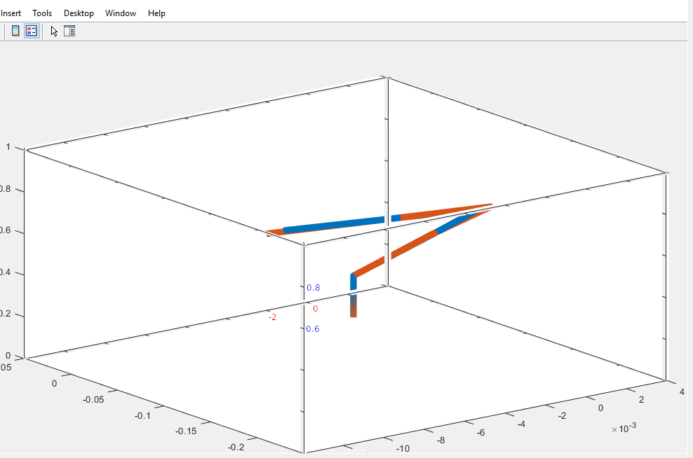
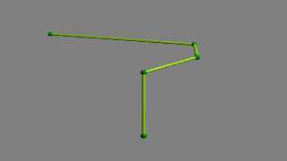
Here's an image rendered with that code.
Btw.
I reached the same conclusion as m@b:
The posted spline code does not generate a spline with the same shape as the one
that is shown in the original screenshot.
Also, it does not fit inside the "wireframe" box in the attached image.
Further, the image is cropped a bit too tight:
On one of the axes we can see that there is a 10^-3 axis multiplier, but it is
not possible to see if this also applies to the other 2 axes.
--
Tor Olav
http://subcube.com
https://github.com/t-o-k
Post a reply to this message
Attachments:
Download 'cameraplacementquestion.png' (24 KB)
Preview of image 'cameraplacementquestion.png'
|
|
| |
| |
|
|
|
|
| |
| |
|
|
"Tor Olav Kristensen" <tor### [at] TOBEREMOVEDgmailcom> wrote:
> Hehe, there you tempted me to have a look at this.
>
> I opened the screenshot in gimp and copied the 3 axes around to check if the
> camera used could be a orthographic camera. It seems so.
Ah. It didn't seem to be a purely perspective view, but it was early and I was
heading out. It certainly had that "view-camera corrected film-plane" look, if
you know what I mean.
Perhaps some of the work done with Norbert Kern's 'Position-Finder' tool could
be used to back-calculate points for the spline to get something that more
closely resembles the posted 3rd-party software graphic.
.... or the original data set could be posted. ;)
Post a reply to this message
|
|
| |
| |
|
|
|
|
| |
| |
|
|
"Bald Eagle" <cre### [at] netscapenet> wrote:
> "Tor Olav Kristensen" <tor### [at] TOBEREMOVEDgmailcom> wrote:
>
> > Hehe, there you tempted me to have a look at this.
> >
> > I opened the screenshot in gimp and copied the 3 axes around to check if the
> > camera used could be a orthographic camera. It seems so.
>
> Ah. It didn't seem to be a purely perspective view, but it was early and I was
> heading out. It certainly had that "view-camera corrected film-plane" look, if
> you know what I mean.
>
> Perhaps some of the work done with Norbert Kern's 'Position-Finder' tool could
> be used to back-calculate points for the spline to get something that more
> closely resembles the posted 3rd-party software graphic.
I've now hat a look at his macro. It seems that what it could be used for in
this case, is to calculate the coordinates of the corners of the box projected
onto a plane.
But the same could be achieved with less work by loading the image into e.g.
Gimp and then finding the coordinates of the corners within the cameras view
plane.
From these coordinates, it may be possible to solve several equations with
several unknowns to find the possible camera vectors.
> .... or the original data set could be posted. ;)
Yes.
But I'm now wondering if the original poster used another spline type in the
other tool. The spline type in the POV-Ray code is "b_spline". But I've not been
able to find out what spline type that is supposed to be. I very much doubt that
it is the B-splines described here:
https://en.wikipedia.org/wiki/B-spline
Perhaps the b stands for Bezier (?) Maybe someone can verify this...
--
Tor Olav
http://subcube.com
https://github.com/t-o-k
Post a reply to this message
|
|
| |
| |
|
|
|
|
| |
|
|