|
 |
"Bald Eagle" <cre### [at] netscape net> wrote:
> "Aj" <nomail@nomail> wrote:
> > Hello everyone,
> >
> > I created a spline object using the following code, but I could not get the
> > proper camera position. I was wondering if there is some systematic way to
> > figure out the camera position, and angle and look at vectors for a given shape.
>
> Yours might be easier, given that you have the grid locations on axes to guide
> you.
>
> Try imagining how the image you posted could be rotated in reverse to straighten
> the axes in the camera frustrum, and use those transforms on the object.
> The actual camera position might be a bit of trial and error to get exactly
> right.
>
> The look_at position might be obtained by extrapolating the x/z grid ticks and
> applying that inverse rotate transform.
>
> Maybe Francois LeCoat has a clever solution, as this seems right up his alley,
> or TOK has some words/code lines of wisdom to offer.
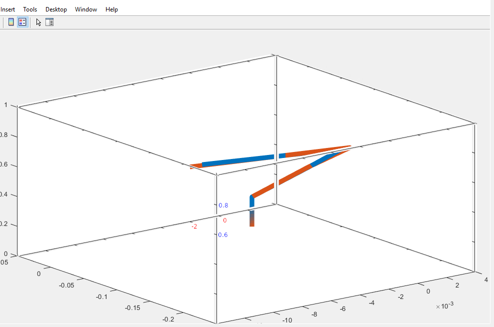
Hehe, there you tempted me to have a look at this.
I opened the screenshot in gimp and copied the 3 axes around to check if the
camera used could be a orthographic camera. It seems so.
See the attached image.
And here's some code ;-)
// ===== 1 ======= 2 ======= 3 ======= 4 ======= 5 ======= 6 ======= 7
// Render options: +w640 +h480 +a0.3
#version 3.7;
global_settings { assumed_gamma 1.0 }
#include "colors.inc"
default {
texture {
pigment { color White }
finish {
diffuse 0
emission color White
}
}
}
// ===== 1 ======= 2 ======= 3 ======= 4 ======= 5 ======= 6 ======= 7
// Extreme values on the axes
#declare XN0 = -14.00; // *1e-3
#declare XP0 = +4.00; // *1e-3
#declare YN0 = 0.00; // *1e-3 ?
#declare YP0 = +1.00; // *1e-3 ?
#declare ZN0 = -0.25; // *1e-3 ?
#declare ZP0 = +0.05; // *1e-3 ?
// Divisions on the axes
#declare DivX0 = 2.00; // *1e-3
#declare DivY0 = 0.20; // *1e-3 ?
#declare DivZ0 = 0.05; // *1e-3 ?
// Number of divisions from the center of
// each axis to the axis endpoints
#declare XN1 = -4.5;
#declare XP1 = +4.5;
#declare YN1 = -2.5;
#declare YP1 = +2.5;
#declare ZN1 = -3.0;
#declare ZP1 = +3.0;
// These were found by trail and error
#declare ScaleX = 1.10;
#declare ScaleY = 0.96;
#declare ScaleZ = 1.64;
#declare FnX =
function(x) {
ScaleX*(XN1 + (x - XN0)/(XP0 - XN0)*(XP1 - XN1))
}
;
#declare FnY =
function(y) {
ScaleY*(YN1 + (y - YN0)/(YP0 - YN0)*(YP1 - YN1))
}
;
#declare FnZ =
function(z) {
ScaleZ*(ZN1 + (z - ZN0)/(ZP0 - ZN0)*(ZP1 - ZN1))
}
;
#declare XN2 = FnX(XN0);
#declare XP2 = FnX(XP0);
#declare YN2 = FnY(YN0);
#declare YP2 = FnY(YP0);
#declare ZN2 = FnZ(ZN0);
#declare ZP2 = FnZ(ZP0);
#declare pNNN = <XN2, YN2, ZN2>;
#declare pPNN = <XP2, YN2, ZN2>;
#declare pPNP = <XP2, YN2, ZP2>;
#declare pNNP = <XN2, YN2, ZP2>;
#declare pNPN = <XN2, YP2, ZN2>;
#declare pPPN = <XP2, YP2, ZN2>;
#declare pPPP = <XP2, YP2, ZP2>;
#declare pNPP = <XN2, YP2, ZP2>;
#declare CylinderRadius = 0.02;
union {
union {
cylinder { pNNN, pPNN, CylinderRadius }
cylinder { pNNP, pPNP, CylinderRadius }
cylinder { pNPN, pPPN, CylinderRadius }
cylinder { pNPP, pPPP, CylinderRadius }
pigment { color Red }
}
union {
cylinder { pNNN, pNPN, CylinderRadius }
cylinder { pPNN, pPPN, CylinderRadius }
cylinder { pPNP, pPPP, CylinderRadius }
cylinder { pNNP, pNPP, CylinderRadius }
pigment { color Green }
}
union {
cylinder { pPNN, pPNP, CylinderRadius }
cylinder { pNNN, pNNP, CylinderRadius }
cylinder { pPPN, pPPP, CylinderRadius }
cylinder { pNPN, pNPP, CylinderRadius }
pigment { color Blue }
}
}
#declare TickRadius = 2*CylinderRadius;
#declare TicksX =
union {
#for (X, XN0 + DivX0, XP0 - DivX0, DivX0)
sphere { FnX(X)*x, TickRadius }
#end // for
}
#declare TicksY =
union {
#for (Y, YN0 + DivY0, YP0 - DivY0, DivY0)
sphere { FnY(Y)*y, TickRadius }
#end // for
}
#declare TicksZ =
union {
#for (Z, ZN0 + DivZ0, ZP0 - DivZ0, DivZ0)
sphere { FnZ(Z)*z, TickRadius }
#end // for
}
union {
object {
TicksX
translate <0, YN2, ZN2>
}
object {
TicksX
translate <0, YP2, ZN2>
}
object {
TicksX
translate <0, YP2, ZP2>
}
object {
TicksX
translate <0, YN2, ZP2>
}
pigment { color White }
}
union {
object {
TicksY
translate <XN2, 0, ZN2>
}
object {
TicksY
translate <XP2, 0, ZN2>
}
object {
TicksY
translate <XP2, 0, ZP2>
}
object {
TicksY
translate <XN2, 0, ZP2>
}
pigment { color White }
}
union {
object {
TicksZ
translate <XN2, YN2, 0>
}
object {
TicksZ
translate <XP2, YN2, 0>
}
object {
TicksZ
translate <XP2, YP2, 0>
}
object {
TicksZ
translate <XN2, YP2, 0>
}
pigment { color White }
}
#declare SphereRadius = 2*TickRadius;
union {
sphere { pNNN, SphereRadius }
sphere { pPNN, SphereRadius }
sphere { pPNP, SphereRadius }
sphere { pNNP, SphereRadius }
sphere { pNPN, SphereRadius }
sphere { pPPN, SphereRadius }
sphere { pPPP, SphereRadius }
sphere { pNPP, SphereRadius }
pigment { color White }
}
background { color Gray20 }
camera {
orthographic
location <-10.8, +4.9, -14.0>*0.6 // Found by trail and error
look_at < 0, 0, 0>
}
// ===== 1 ======= 2 ======= 3 ======= 4 ======= 5 ======= 6 ======= 7
--
Tor Olav
http://subcube.com
https://github.com/t-o-k net> wrote:
> "Aj" <nomail@nomail> wrote:
> > Hello everyone,
> >
> > I created a spline object using the following code, but I could not get the
> > proper camera position. I was wondering if there is some systematic way to
> > figure out the camera position, and angle and look at vectors for a given shape.
>
> Yours might be easier, given that you have the grid locations on axes to guide
> you.
>
> Try imagining how the image you posted could be rotated in reverse to straighten
> the axes in the camera frustrum, and use those transforms on the object.
> The actual camera position might be a bit of trial and error to get exactly
> right.
>
> The look_at position might be obtained by extrapolating the x/z grid ticks and
> applying that inverse rotate transform.
>
> Maybe Francois LeCoat has a clever solution, as this seems right up his alley,
> or TOK has some words/code lines of wisdom to offer.
Hehe, there you tempted me to have a look at this.
I opened the screenshot in gimp and copied the 3 axes around to check if the
camera used could be a orthographic camera. It seems so.
See the attached image.
And here's some code ;-)
// ===== 1 ======= 2 ======= 3 ======= 4 ======= 5 ======= 6 ======= 7
// Render options: +w640 +h480 +a0.3
#version 3.7;
global_settings { assumed_gamma 1.0 }
#include "colors.inc"
default {
texture {
pigment { color White }
finish {
diffuse 0
emission color White
}
}
}
// ===== 1 ======= 2 ======= 3 ======= 4 ======= 5 ======= 6 ======= 7
// Extreme values on the axes
#declare XN0 = -14.00; // *1e-3
#declare XP0 = +4.00; // *1e-3
#declare YN0 = 0.00; // *1e-3 ?
#declare YP0 = +1.00; // *1e-3 ?
#declare ZN0 = -0.25; // *1e-3 ?
#declare ZP0 = +0.05; // *1e-3 ?
// Divisions on the axes
#declare DivX0 = 2.00; // *1e-3
#declare DivY0 = 0.20; // *1e-3 ?
#declare DivZ0 = 0.05; // *1e-3 ?
// Number of divisions from the center of
// each axis to the axis endpoints
#declare XN1 = -4.5;
#declare XP1 = +4.5;
#declare YN1 = -2.5;
#declare YP1 = +2.5;
#declare ZN1 = -3.0;
#declare ZP1 = +3.0;
// These were found by trail and error
#declare ScaleX = 1.10;
#declare ScaleY = 0.96;
#declare ScaleZ = 1.64;
#declare FnX =
function(x) {
ScaleX*(XN1 + (x - XN0)/(XP0 - XN0)*(XP1 - XN1))
}
;
#declare FnY =
function(y) {
ScaleY*(YN1 + (y - YN0)/(YP0 - YN0)*(YP1 - YN1))
}
;
#declare FnZ =
function(z) {
ScaleZ*(ZN1 + (z - ZN0)/(ZP0 - ZN0)*(ZP1 - ZN1))
}
;
#declare XN2 = FnX(XN0);
#declare XP2 = FnX(XP0);
#declare YN2 = FnY(YN0);
#declare YP2 = FnY(YP0);
#declare ZN2 = FnZ(ZN0);
#declare ZP2 = FnZ(ZP0);
#declare pNNN = <XN2, YN2, ZN2>;
#declare pPNN = <XP2, YN2, ZN2>;
#declare pPNP = <XP2, YN2, ZP2>;
#declare pNNP = <XN2, YN2, ZP2>;
#declare pNPN = <XN2, YP2, ZN2>;
#declare pPPN = <XP2, YP2, ZN2>;
#declare pPPP = <XP2, YP2, ZP2>;
#declare pNPP = <XN2, YP2, ZP2>;
#declare CylinderRadius = 0.02;
union {
union {
cylinder { pNNN, pPNN, CylinderRadius }
cylinder { pNNP, pPNP, CylinderRadius }
cylinder { pNPN, pPPN, CylinderRadius }
cylinder { pNPP, pPPP, CylinderRadius }
pigment { color Red }
}
union {
cylinder { pNNN, pNPN, CylinderRadius }
cylinder { pPNN, pPPN, CylinderRadius }
cylinder { pPNP, pPPP, CylinderRadius }
cylinder { pNNP, pNPP, CylinderRadius }
pigment { color Green }
}
union {
cylinder { pPNN, pPNP, CylinderRadius }
cylinder { pNNN, pNNP, CylinderRadius }
cylinder { pPPN, pPPP, CylinderRadius }
cylinder { pNPN, pNPP, CylinderRadius }
pigment { color Blue }
}
}
#declare TickRadius = 2*CylinderRadius;
#declare TicksX =
union {
#for (X, XN0 + DivX0, XP0 - DivX0, DivX0)
sphere { FnX(X)*x, TickRadius }
#end // for
}
#declare TicksY =
union {
#for (Y, YN0 + DivY0, YP0 - DivY0, DivY0)
sphere { FnY(Y)*y, TickRadius }
#end // for
}
#declare TicksZ =
union {
#for (Z, ZN0 + DivZ0, ZP0 - DivZ0, DivZ0)
sphere { FnZ(Z)*z, TickRadius }
#end // for
}
union {
object {
TicksX
translate <0, YN2, ZN2>
}
object {
TicksX
translate <0, YP2, ZN2>
}
object {
TicksX
translate <0, YP2, ZP2>
}
object {
TicksX
translate <0, YN2, ZP2>
}
pigment { color White }
}
union {
object {
TicksY
translate <XN2, 0, ZN2>
}
object {
TicksY
translate <XP2, 0, ZN2>
}
object {
TicksY
translate <XP2, 0, ZP2>
}
object {
TicksY
translate <XN2, 0, ZP2>
}
pigment { color White }
}
union {
object {
TicksZ
translate <XN2, YN2, 0>
}
object {
TicksZ
translate <XP2, YN2, 0>
}
object {
TicksZ
translate <XP2, YP2, 0>
}
object {
TicksZ
translate <XN2, YP2, 0>
}
pigment { color White }
}
#declare SphereRadius = 2*TickRadius;
union {
sphere { pNNN, SphereRadius }
sphere { pPNN, SphereRadius }
sphere { pPNP, SphereRadius }
sphere { pNNP, SphereRadius }
sphere { pNPN, SphereRadius }
sphere { pPPN, SphereRadius }
sphere { pPPP, SphereRadius }
sphere { pNPP, SphereRadius }
pigment { color White }
}
background { color Gray20 }
camera {
orthographic
location <-10.8, +4.9, -14.0>*0.6 // Found by trail and error
look_at < 0, 0, 0>
}
// ===== 1 ======= 2 ======= 3 ======= 4 ======= 5 ======= 6 ======= 7
--
Tor Olav
http://subcube.com
https://github.com/t-o-k
Post a reply to this message
Attachments:
Download 'orthographiccamera.png' (47 KB)
Preview of image 'orthographiccamera.png'
|
|