|
|
|
|
|
|
| |
| |
|
|
|
|
| |
| |
|
|
> hey wow ... making some progress! Did they link I put up spark an idea?
Thanks. No not yet. Still working at some other tweaks of my testing before
adding some subsampling. I do have some ideas for what I want to try for
sub-sampling. There are two different levels:
1) grid sampling level - rather specifying my starting grid size with a large
resolution, I may try smaller and have it subsample based on intersections.
2) number of crevice traces shot - with this, I would specify a base level (say
4 at 90deg spacing) and then subsample based on intersections found
Of these, #2 is the easiest and most applicable perhaps. The first item is for
my current scene level testing only where I have to manually set and run the
traces. The idea would eventually be that it is a pattern in the code that uses
the camera rays themselves. In this case, any resolution subsampling required
would be probably handled by AA settings.
Post a reply to this message
|
|
| |
| |
|
|
|
|
| |
| |
|
|
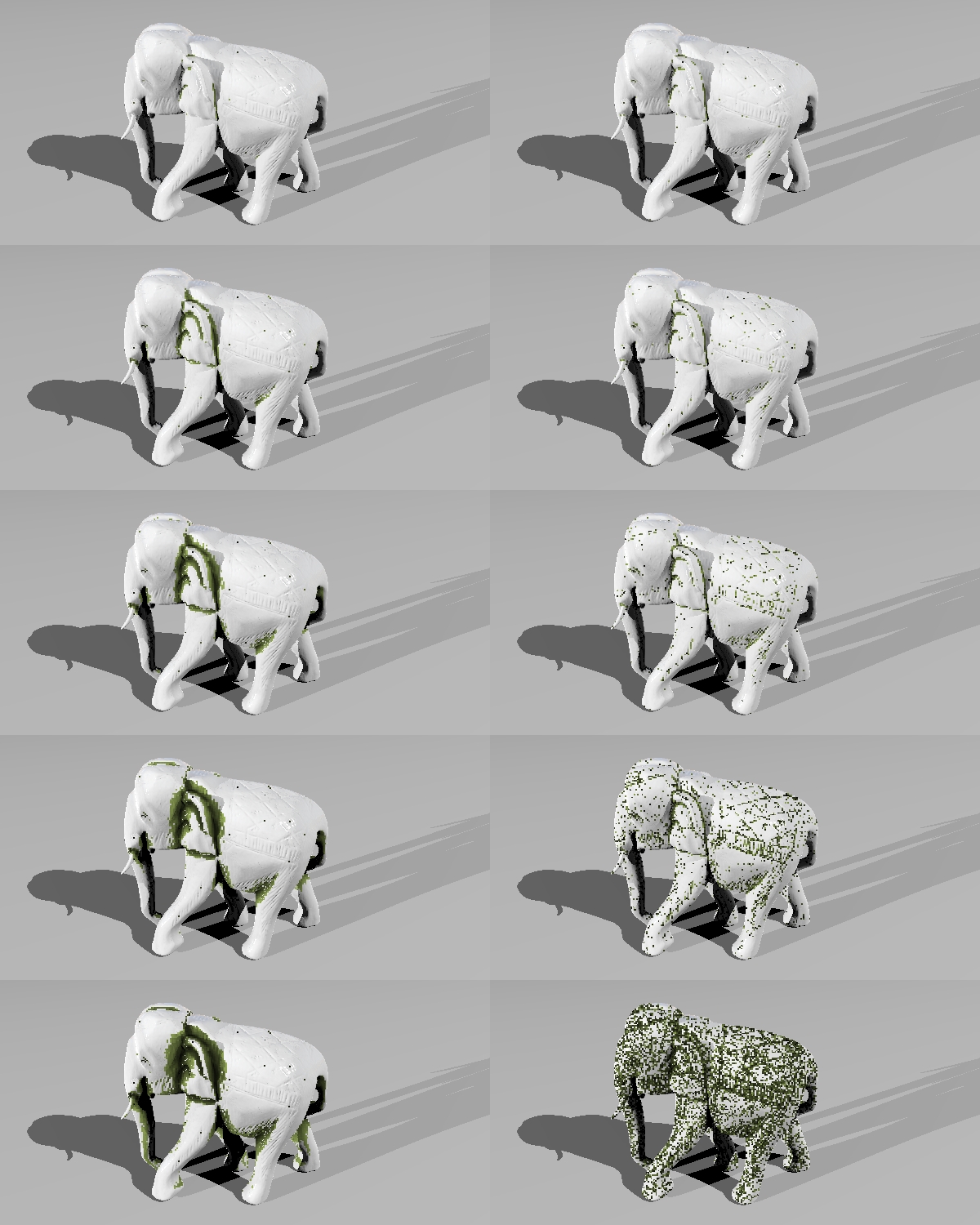
A quick little posting exhibiting the effects of two of the parameters.
For reference, the model is 200 (units) high. Again I have used coarser
resolution for speed purposes which is what makes it look pixelly (grime
'pixels' are larger than image pixels).
The top left is the main control image with a setting of:
control depth = 5 (units), normal angle = 60 (degrees)
the remaining 4 images on the left side retain the normal angle of 60, but
increase control depth: 20, 50, 100 & 200
the 5 images on the left side retain the control depth of 5, but increase normal
angle: 65, 70, 75, 80 & 85.
A few effects can be noted:
-the size of the control depth effects how large of crevice widths effect the
grime build-up. We can see that the shallow patterns on the back don't get
picked up, but more open or larger areas get affected (e.g. underside of model)
-increasing control depth also affects the value of the grime deeper in the
crevice
-changing the normal angle effects how shallow crevices effect the grime
build-up. This time we can see with shallower (greater) angles, the shallow
patterns on the back start to get picked up. However in more wide open areas,
we don't see the grime build-up (e.g. underside of model again)
with the very shallow angle (85), the whole model gets affected. I don't know
whether this is picking up very minor indentations, but it looks more like it is
a result of the model mesh resolution
More to do, but this is looking pretty satisfying at present.
-tgq
Post a reply to this message
Attachments:
Download 'trace9.jpg' (640 KB)
Preview of image 'trace9.jpg'
|
|
| |
| |
|
|
|
|
| |
| |
|
|
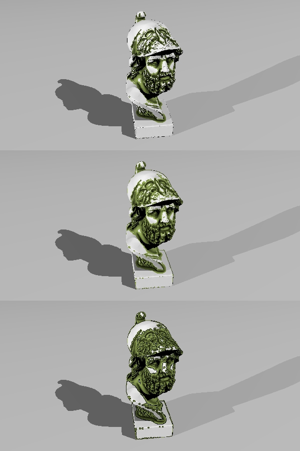
"Trevor G Quayle" <Tin### [at] hotmail com> wrote:
> Another test on a more complex mesh object. Here I have run 3 different
> instances. Note each one has to be run separately and translated/rotated before
> running the algorithm, otherwise the untraced areas would be visible.
>
> Here the general object size is 200units high. Crevice checking is done for a
> control depth of 15units, normal angle of 75deg, 16 traces per point.
>
> I also changed the object I am using to show my crevice solouring, I am now
> using mesh 'pixels' that extend back into the camera point (mesh because they
> are a 4-sided pyramid of sorts), but intersected with the base object. This way
> I get a sharp transition from each pixel, with no overlap. One downfall of this
> is that I have to texture my base object after using it in the grime (or use an
> untextured instance) as the intersection CSG operation causes my grime pixel to
> adopt the base object texture otherwise.
>
> The grime is a little pixelated here, because my general pixel size is ~2x that
> for the image resolution.
>
> -tgq
Nice, this is really starting to come together, looking good. What's the parse
time for the grime algorithm per head mesh here?
-------------------------------------------------
www.McGregorFineArt.com com> wrote:
> Another test on a more complex mesh object. Here I have run 3 different
> instances. Note each one has to be run separately and translated/rotated before
> running the algorithm, otherwise the untraced areas would be visible.
>
> Here the general object size is 200units high. Crevice checking is done for a
> control depth of 15units, normal angle of 75deg, 16 traces per point.
>
> I also changed the object I am using to show my crevice solouring, I am now
> using mesh 'pixels' that extend back into the camera point (mesh because they
> are a 4-sided pyramid of sorts), but intersected with the base object. This way
> I get a sharp transition from each pixel, with no overlap. One downfall of this
> is that I have to texture my base object after using it in the grime (or use an
> untextured instance) as the intersection CSG operation causes my grime pixel to
> adopt the base object texture otherwise.
>
> The grime is a little pixelated here, because my general pixel size is ~2x that
> for the image resolution.
>
> -tgq
Nice, this is really starting to come together, looking good. What's the parse
time for the grime algorithm per head mesh here?
-------------------------------------------------
www.McGregorFineArt.com
Post a reply to this message
|
|
| |
| |
|
|
|
|
| |
| |
|
|
> Nice, this is really starting to come together, looking good. What's the parse
> time for the grime algorithm per head mesh here?
I am using very low testing settings so I can get quick results, but parsing
depends on the sample resolution, and number of normals traced. On my home
machine, with res set to 400, number of trces set to 32, this parsed in
~30seconds, including ~7seconds to load the mesh (~35MB). Rendering is another
40secs on top of that, mostly because of all the intersections for each
grime-pixel. I've been think about a way to try to make a procedural texture
out of it rather than the current method.
-tgq
Post a reply to this message
|
|
| |
| |
|
|
|
|
| |
| |
|
|
"Trevor G Quayle" <Tin### [at] hotmailcom> wrote:
> > Nice, this is really starting to come together, looking good. What's the parse
> > time for the grime algorithm per head mesh here?
>
> I am using very low testing settings so I can get quick results, but parsing
> depends on the sample resolution, and number of normals traced. On my home
> machine, with res set to 400, number of trces set to 32, this parsed in
> ~30seconds, including ~7seconds to load the mesh (~35MB). Rendering is another
> 40secs on top of that, mostly because of all the intersections for each
> grime-pixel. I've been think about a way to try to make a procedural texture
> out of it rather than the current method.
>
> -tgq
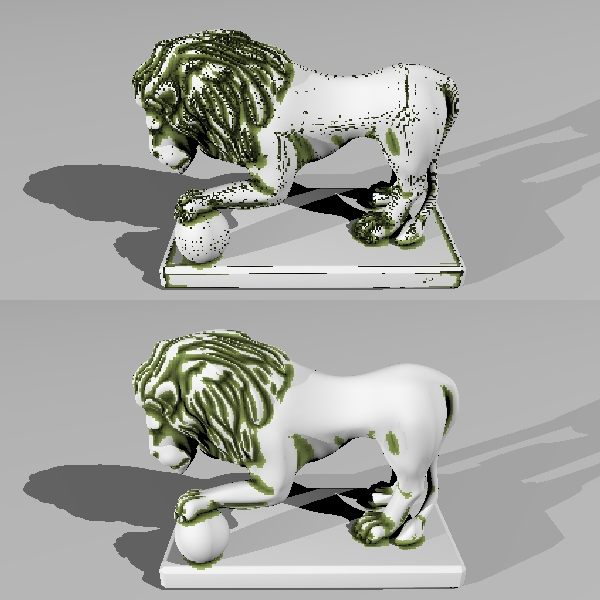
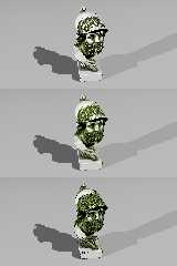
I figured out a way to convert my number to a pigment: save to an array, export
as .df3 file and read in as density_file pattern. This speeds it up
considerably on the render time. The average render time for the heads shown
with a ersoltuion setting of 400 was about 30sec compared to over 60sec
previously, with the majority (26s) being parse time. I gave me the offshoot
ability of using the interpolate function for density files. The 2nd image ins
with interpolate 1, and the 3rd is with interpolate 2. The interpolate 2 seems
to cause banding at the transition points. Interpolate 1 is ok (there are
issues at smaller resolutions though.
One thing I noticed is that with interpolate 1 there is a distinct shift down
and to the left. Is there a bias in the internal interpolate function? This is
something that I have noticed before with interpolate.
-tgq
Post a reply to this message
Attachments:
Download 'trace-4.jpg' (135 KB)
Preview of image 'trace-4.jpg'
|
|
| |
| |
|
|
|
|
| |
| |
|
|
> One thing I noticed is that with interpolate 1 there is a distinct shift down
> and to the left. Is there a bias in the internal interpolate function? This is
> something that I have noticed before with interpolate.
Yeah - it's to do with where you consider the authoritative pixel value to be -
in the center of the voxel, or in the lower corner.
I remember writing code to correct for exactly that in my DF3 proximity code. I
need to look at it again, as it might have changed during the 3.7 beta cycle
(there was a post about interpolation a few months back I recall).
Cheers,
Edouard.
Post a reply to this message
|
|
| |
| |
|
|
|
|
| |
| |
|
|
Am 17.03.2011 03:49, schrieb Trevor G Quayle:
> The interpolate 2 seems to cause banding at the transition points.
Cubic interpolation produces "overshoot" and "undershoot" at sharp
transitions. I usually store values from 0.25 to 0.75 in df3 files to
avoid such problems.
> One thing I noticed is that with interpolate 1 there is a distinct shift down
> and to the left. Is there a bias in the internal interpolate function? This is
> something that I have noticed before with interpolate.
It was known (and fixed) for interpolation of input images, but has
never been examined for df3 files yet.
Post a reply to this message
|
|
| |
| |
|
|
|
|
| |
| |
|
|
"Edouard" <pov### [at] edouardinfo> wrote:
> > One thing I noticed is that with interpolate 1 there is a distinct shift down
> > and to the left. Is there a bias in the internal interpolate function? This is
> > something that I have noticed before with interpolate.
>
> Yeah - it's to do with where you consider the authoritative pixel value to be -
> in the center of the voxel, or in the lower corner.
>
> I remember writing code to correct for exactly that in my DF3 proximity code. I
> need to look at it again, as it might have changed during the 3.7 beta cycle
> (there was a post about interpolation a few months back I recall).
>
> Cheers,
> Edouard.
I added a half pixel shift to the interpolated version and it seems correct that
way. Looks like it may need updating in 3.7 to correct this.
-tgq
Post a reply to this message
|
|
| |
| |
|
|
|
|
| |
| |
|
|
clipka <ano### [at] anonymousorg> wrote:
> Am 17.03.2011 03:49, schrieb Trevor G Quayle:
>
> > The interpolate 2 seems to cause banding at the transition points.
>
> Cubic interpolation produces "overshoot" and "undershoot" at sharp
> transitions. I usually store values from 0.25 to 0.75 in df3 files to
> avoid such problems.
I guess this is partly the wrap-around banding. I have tried a few fixes, but
none are satisfactory. Probably just best to not use interpolate 2 for my
current usage and stick with linear or perahps my own function coded
interpolation.
>
> > One thing I noticed is that with interpolate 1 there is a distinct shift down
> > and to the left. Is there a bias in the internal interpolate function? This is
> > something that I have noticed before with interpolate.
>
> It was known (and fixed) for interpolation of input images, but has
> never been examined for df3 files yet.
I ran a test with a 1/2 pixel shift which corrected it, so it does look like
this just needs to be corrected for df3 files in the code.
-tgq
Post a reply to this message
|
|
| |
| |
|
|
|
|
| |
| |
|
|
Had a look at addressing the issue I was having with shallow angles picking up
ridges. I did some testing and found that this is a result of how trace works
(on smooth meshes in particular). The intersection returned is the intersection
with the flat, unsmoothed surface of the mesh (unperturbed), whereas the surface
normal returned is based on the smoothed surface normal at the point. What
happens is that very shallow traces end up intersecting with the mesh in some
locations, particularly close to triangle edges.
I thought of several solutions to avoid this:
1) have the trace function return the perturbed intersection point, not the
triangle surface: this would have to be done in the POV source. I imagine this
is difficult if not nearly impossible, hence we still get the shadow line issue
with meshes. Not likely solution at present.
2) have the trace function return the unperturbed normal at the intersection:
again this would have to be done in the POV source and would be much simpler, if
not trivial to do compared to 1. However this would change the way trace works
and, in most situations, may not be desirable, and could break older scenes.
Not likely solution.
3) manual method of 2), have two instances of the mesh used, one smoothed, one
not. the smoothed one gets used for rendering, the unsmoothed for tracing: Not
an elegant solution as it requires creating and loading two separate instances
of the same mesh.
4) similar to 3), but have encoded in mesh objects and additional "unsmooth"
keyword that would allow for the mesh smoothing to be ignored for certain
circumstances: Again, this would require POV source coding, but may be simple
to do from a coding perspective without breaking old scenes. However, not
likely a curren t solution unless I want to get into source coding.
5) manual method of 1), this is not strictly equivalent to 1, but basically
manually set an offset value to start the traces from. Essentially the initial
trace sets the intersection point and grabs the surface normal, but the
subsequent grime traces start from a point just off the surface: Very simple
flexible solution from the user standpoint as testing can be done to find the
optimal offset to use, doesn't require internal coding of trace handling.
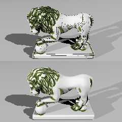
Following my simple solution #5, I added this capability into my current macro
with good results. See the attached image. For reference, the model is 200
units high, normal angle set to 85, control depth set to 20. The first image is
run with no offset. Distinct artifacts and mesh lines can be seen, particularly
the lines along the body and legs. The second image uses the same parameters
but with a offset of 0.1 with fairly favourable results.
-tgq
Post a reply to this message
Attachments:
Download 'trace2.jpg' (166 KB)
Preview of image 'trace2.jpg'
|
|
| |
| |
|
|
|
|
| |
|
|