|
|
|
|
|
|
| |
| |
|
|
|
|
| |
| |
|
|
wayne461 wrote:
> So do you know if the eval_3d_spline macro converted into POVRAY 3.6
> anywhere?
Don't know. I barely remember it or it's history, where it came in etc.
I think I used it but really didn't understand the value added.
Probably too subtle for me. But it doesn't add anything significant
here. It just returns a point on the spline afaik
>
Anyway I came up with a brute force seam spline which you can find
posted in p.b.scene-files. There is also some code there for walking
the spline and creating a parallel set of points on either side of a seam.
Post a reply to this message
|
|
| |
| |
|
|
|
|
| |
| |
|
|
Jim Charter <jrc### [at] msn com> wrote:
> Anyway I came up with a brute force seam spline which you can find
> posted in p.b.scene-files. There is also some code there for walking
> the spline and creating a parallel set of points on either side of a seam.
Wow, that spline is great!!! We are really close. Thanks for all your
help!!
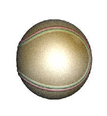
Okay, so I integrated everything we have so far and put it in the same
thread in p.b.scene file. It looks a little elongated in the y direction.
I don't quite now why but it may be the camera and the "up" or "direction"
I left from the older scene. I rendered it at 2960 by 1920 so the ratio was
the same as 640/480 like in the camera definition.
If I could bother you some more...Part of the code is stil beyond my ability
though. Did you envision the "cross" as the part of the code allowing me to
walk the spline and make a red cylinder between theparallel set of points on
either side of a seam to make red stiches along the seam?
Here is the work in progress so far: com> wrote:
> Anyway I came up with a brute force seam spline which you can find
> posted in p.b.scene-files. There is also some code there for walking
> the spline and creating a parallel set of points on either side of a seam.
Wow, that spline is great!!! We are really close. Thanks for all your
help!!
Okay, so I integrated everything we have so far and put it in the same
thread in p.b.scene file. It looks a little elongated in the y direction.
I don't quite now why but it may be the camera and the "up" or "direction"
I left from the older scene. I rendered it at 2960 by 1920 so the ratio was
the same as 640/480 like in the camera definition.
If I could bother you some more...Part of the code is stil beyond my ability
though. Did you envision the "cross" as the part of the code allowing me to
walk the spline and make a red cylinder between theparallel set of points on
either side of a seam to make red stiches along the seam?
Here is the work in progress so far:
Post a reply to this message
Attachments:
Download 'baseball with spline wip.jpg' (56 KB)
Preview of image 'baseball with spline wip.jpg'
|
|
| |
| |
|
|
|
|
| |
| |
|
|
Among other things, Jim Charter saw fit to write:
> Anyway I came up with a brute force seam spline which you can find
> posted in p.b.scene-files. There is also some code there for walking
> the spline and creating a parallel set of points on either side of a seam.
You may find this interesting:
http://www.mathcurve.com/courbes3d/couture/couture.shtml
--
light_source{9+9*x,1}camera{orthographic look_at(1-y)/4angle 30location
9/4-z*4}light_source{-9*z,1}union{box{.9-z.1+x clipped_by{plane{2+y-4*x
0}}}box{z-y-.1.1+z}box{-.1.1+x}box{.1z-.1}pigment{rgb<.8.2,1>}}//Jellby
Post a reply to this message
|
|
| |
| |
|
|
From: Jim Charter
Subject: Re: Can we join together to make a baseball?
Date: 17 Apr 2006 05:08:40
Message: <44435b18@news.povray.org>
|
|
|
| |
| |
|
|
wayne461 wrote:
> If I could bother you some more...Part of the code is stil beyond my ability
> though. Did you envision the "cross" as the part of the code allowing me to
> walk the spline and make a red cylinder between theparallel set of points on
> either side of a seam to make red stiches along the seam?
>
Yes but it is also how I made the parallel bunching along the seam. The
vcross gives the cross product. The cross product of two vectors gives
a vector that is perpendicular to the plane of the two vectors you take
the cross product of.
So here's how it works:
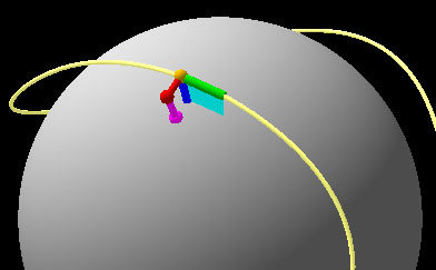
In my illustration you can see that the actual spline rides above the
surface of the sphere. (Jellby's contribution my eliminate the need for
this but...later* )
The orange ball is some point on the spline as we loop along it:
SeamSpline(I/Grain)
The green cylinder is a segment of the spline which I called Seg
SeamSpline(I/Grain)-SeamSpline((I-1)/Grain)
The blue cylinder runs perpendicular to the ball's surface from
the orange ball which I call Norm
The cyan plane is the plane that the two vectors Norm and Seg lie in
The red cylinder is the cross product of the Norm and Seg vectors and
is therefore perpendicular to the cyan plane.
I use it to locate a point along-side the spline, the red sphere
Now you see in the code that I use the trace() function.
This function finds the point where the magenta cylinder intersects
the ball's surface, marked by the magenta sphere. The magenta cylinder
is nothing more that the path from the red sphere to the center of the
ball. The magenta sphere is the same as the spherical blob components
that I use to make the lumps along the seam.
* But now with Jelby's contribution it is probably possible to define
points directly on the surface of a sphere, thus obviating much of this.
Post a reply to this message
Attachments:
Download 'img.0000.jpg' (25 KB)
Preview of image 'img.0000.jpg'

|
|
| |
| |
|
|
|
|
| |
| |
|
|
> This function finds the point where the magenta cylinder intersects
> the ball's surface, marked by the magenta sphere. The magenta cylinder
> is nothing more that the path from the red sphere to the center of the
> ball. The magenta sphere is the same as the spherical blob components
> that I use to make the lumps along the seam.
>
> * But now with Jelby's contribution it is probably possible to define
> points directly on the surface of a sphere, thus obviating much of this.
Glad to see this is coming together with so much help from Jim and now
Jelby.
It seems for a basball we still may want the seam to be just above the ball.
On baseball it makes a slight ridge there so maybe it would need to be toned
down from the current code, Jim?
I am posting a link to a real upclose image of an actual baseball to support
this.
http://images.google.com/imgres?imgurl=http://www.justinnewitter.com/stock/Baseball.JPG&imgrefurl=http://www.justinnewi
tter.com/stock/page_01.htm&h=1600&w=1200&sz=521&tbnid=1MNLzbzsnPsJ:&tbnh=149&tbnw=112&prev=/images%3Fq%3Dbaseball%26hl%
3Den%26lr%3D&start=1&sa=X&oi=images&ct=image&cd=1
However, I think now Jelby's lead might help us more finely code the holes
in the ball and stitches exiting and going into ball? Is that how you see
things proceeding, Jim? Do you want me to play around and see what I can
come up with?
Post a reply to this message
|
|
| |
| |
|
|
|
|
| |
| |
|
|
wayne461 wrote:
> However, I think now Jelby's lead might help us more finely code the holes
> in the ball and stitches exiting and going into ball? Is that how you see
> things proceeding, Jim? Do you want me to play around and see what I can
> come up with?
>
The math on the page Jellby quoted might be used to make a more accurate
spline. Not urgent at the moment. Mine is not very accurate. But in my
opinion using a spline gives the ability to work within sdl without
knowing sophisticated math.
The code I showed you was meant as more of a direction than a solution.
For instance the pigment yellow and magenta pigment was included only to
show the influence of the added blob components. A shallower ridge can
be gotten by tweaking down the threshold value ( get it low, maybe .03
or so ) while increasing the radius of the ridge blobs ( maybe .14 )
You migh also notice that I also locate the blobs just under the surface
of the ball.
Also in the original thread you quoted, H E Day posted a suggestion for
how to "feather" the edges ( which was the original question on the
thread.) His suggestin was to replace each blob component with several
in the same place each one trading off radius v strength
So
instead of something like:
Radius=.14
Strength=1
blob { threshold .03
sphere { 0, 1, 1 }
STARTLOOP
sphere ( Location, Radius, Strenght )
ENDLOOP
}
do something like:
Radius1=.10
Strenght1=1.2
Radius2=.12
Strength2=1.1
Radius3=.14
Strenght3=1.0
blob { threshold .03
sphere { 0, 1, 1 }
STARTLOOP
sphere { Location, Radius1, Strength1 }
sphere { Location, Radius2, Strength2 }
sphere { Location, Radius3, Strength3 }
ENDLOOP
}
I think you could try and tweak these factors before we attack the
threading issue.
I am not sure how radically you would need to vary the Radius and
Strenght over the three "copies" in order to get the effect H Day
describes. I have never tried the technique myself. But H E Day was a
blob master. Perhaps try some controlled experiments to assure yourself
of how the technique works before working directly on the ball model.
-Jim
Post a reply to this message
|
|
| |
| |
|
|
|
|
| |
| |
|
|
Jim Charter <jrc### [at] msncom> wrote:
> The code I showed you was meant as more of a direction than a solution.
>
> For instance the pigment yellow and magenta pigment was included only to
> show the influence of the added blob components. A shallower ridge can
> be gotten by tweaking down the threshold value ( get it low, maybe .03
> or so ) while increasing the radius of the ridge blobs ( maybe .14 )
> You migh also notice that I also locate the blobs just under the surface
> of the ball.
>
> Also in the original thread you quoted, H E Day posted a suggestion for
> how to "feather" the edges ( which was the original question on the
> thread.) His suggestin was to replace each blob component with several
> in the same place each one trading off radius v strength
>
> So
>
> instead of something like:
>
> Radius=.14
> Strength=1
> blob { threshold .03
> sphere { 0, 1, 1 }
> STARTLOOP
> sphere ( Location, Radius, Strenght )
>
> ENDLOOP
> }
>
> do something like:
>
> Radius1=.10
> Strenght1=1.2
> Radius2=.12
> Strength2=1.1
> Radius3=.14
> Strenght3=1.0
>
> blob { threshold .03
> sphere { 0, 1, 1 }
> STARTLOOP
> sphere { Location, Radius1, Strength1 }
> sphere { Location, Radius2, Strength2 }
> sphere { Location, Radius3, Strength3 }
> ENDLOOP
> }
>
> I think you could try and tweak these factors before we attack the
> threading issue.
>
> I am not sure how radically you would need to vary the Radius and
> Strenght over the three "copies" in order to get the effect H Day
> describes. I have never tried the technique myself. But H E Day was a
> blob master. Perhaps try some controlled experiments to assure yourself
> of how the technique works before working directly on the ball model.
>
> -Jim
I'll try to go in the direction you have indicated. It will probably be a
few days before I post back what I have put together. It may have to wait
until the weekend. Thanks for your sharing of knowledge.
-Wayne
Post a reply to this message
|
|
| |
| |
|
|
From: Jim Charter
Subject: Re: Can we join together to make a baseball?
Date: 18 Apr 2006 11:06:41
Message: <44450081@news.povray.org>
|
|
|
| |
| |
|
|
wayne461 wrote:
> Jim Charter <jrc### [at] msncom> wrote:
>
>
>>The code I showed you was meant as more of a direction than a solution.
>>
>>For instance the pigment yellow and magenta pigment was included only to
>>show the influence of the added blob components. A shallower ridge can
>>be gotten by tweaking down the threshold value ( get it low, maybe .03
>>or so ) while increasing the radius of the ridge blobs ( maybe .14 )
>>You migh also notice that I also locate the blobs just under the surface
>>of the ball.
>>
>>Also in the original thread you quoted, H E Day posted a suggestion for
>>how to "feather" the edges ( which was the original question on the
>>thread.) His suggestin was to replace each blob component with several
>>in the same place each one trading off radius v strength
>>
>>So
>>
>>instead of something like:
>>
>>Radius=.14
>>Strength=1
>>blob { threshold .03
>> sphere { 0, 1, 1 }
>> STARTLOOP
>> sphere ( Location, Radius, Strenght )
>>
>> ENDLOOP
>>}
>>
>>do something like:
>>
>>Radius1=.10
>>Strenght1=1.2
>>Radius2=.12
>>Strength2=1.1
>>Radius3=.14
>>Strenght3=1.0
>>
>>blob { threshold .03
>> sphere { 0, 1, 1 }
>> STARTLOOP
>> sphere { Location, Radius1, Strength1 }
>> sphere { Location, Radius2, Strength2 }
>> sphere { Location, Radius3, Strength3 }
>> ENDLOOP
>>}
>>
>>I think you could try and tweak these factors before we attack the
>>threading issue.
>>
>>I am not sure how radically you would need to vary the Radius and
>>Strenght over the three "copies" in order to get the effect H Day
>>describes. I have never tried the technique myself. But H E Day was a
>>blob master. Perhaps try some controlled experiments to assure yourself
>>of how the technique works before working directly on the ball model.
>>
>>-Jim
>
>
> I'll try to go in the direction you have indicated. It will probably be a
> few days before I post back what I have put together. It may have to wait
> until the weekend. Thanks for your sharing of knowledge.
> -Wayne
>
You're welcome. I am not sure how much you understand about the
concepts behind these techniques or have knowledge of POV's SDL, but if
you don't you should take this opportunity to research these things.
This is a great project for refining your abilities with vectors,
transforms, and splines. Right now we are operating pretty much at the
limits of my understanding.
Again I want to emphasize that the code* I showed you is quite
abbreviated. Not only can the parameters be tweaked but the code could
and should be further refined.
For instance, right now the "Seg" vector is dependent on the size of the
"step" we use to "walk" along the spline . This, of course is
controlled by the "Grain" value. Seg should be uncoupled from Grain.
Worse, the length of "Cross" is related to the length of "Seg". Cross
should be "normalized" so it is independent of Seg and can be scaled in
POV units.
Also, I would suggest incorporating the rand() function to "jitter" the
placement, even the size, of the blobs forming the ridge so that it
will appear less regular.
*some on the groups here wince when we refer to SDL as "code". To many
hardcore programmers it is "script". Otoh, SDL is also held to be a
"turing-complete" programming language, so go figure.
Post a reply to this message
|
|
| |
| |
|
|
From: Larry Hudson
Subject: Re: Can we join together to make a baseball?
Date: 18 Apr 2006 21:59:24
Message: <4445997c@news.povray.org>
|
|
|
| |
| |
|
|
Jim Charter wrote:
> *some on the groups here wince when we refer to SDL as "code". To many
> hardcore programmers it is "script". Otoh, SDL is also held to be a
> "turing-complete" programming language, so go figure.
Well, my viewpoint is as a non-professional, amateur/hobbyist
programmer, mostly with C. I see the difference between code and a
script as this: code is compiled into a different form (program code
becomes executable machine-language code), while a script is a set of
instructions that are directly run to perform some set of operations.
Rendering SDL is in effect compiling it, where it becomes an image file.
It is not run as a set of instructions, it is a set of descriptions,
therefore it is code and not a script.
Of course, realistically, who cares whether the SDL is called code or
script, that's completely irrelevant. Just use it and enjoy. :-)
Just one (lay-)person's opinion...
-=- Larry -=-
Post a reply to this message
|
|
| |
| |
|
|
|
|
| |
| |
|
|
Jim Charter <jrc### [at] msncom> wrote:
> >
> The math on the page Jellby quoted might be used to make a more accurate
> spline. Not urgent at the moment. Mine is not very accurate. But in my
> opinion using a spline gives the ability to work within sdl without
> knowing sophisticated math.
>
>
> -Jim
I haven't gotten back to this recently but the other day I did stumble upon
another site witht he formula for the baseball seam.
http://astronomy.swin.edu.au/~pbourke/curves/baseball/index.html
Post a reply to this message
|
|
| |
| |
|
|
|
|
| |
|
|