POV-Ray : Newsgroups : povray.binaries.images : Tangents with analytical geomtery Server Time
28 Mar 2024 16:38:27 EDT (-0400)
  Tangents with analytical geomtery (Message 1 to 10 of 18)  
Goto Latest 10 Messages Next 8 Messages >>>
From: Bald Eagle
Subject: Tangents with analytical geomtery
Date: 12 Oct 2019 21:15:01
Message: <web.5da27a2a65c96eb4eec112d0@news.povray.org>
So I tried doing this "the old way" by calculating the angle between the center
line and the tangent and then rotating and translating - but that got too messy
too fast for my second test case, and the first one was hairy enough.

So I implemented a fully analytical method to calculate the endpoints of the
tangent lines "in place" for any arbitrary set of circles.

Input for the macro is just a list of circle centers and radii.

Now to implement some further logic, and then try non-circular "pulleys", and
linear bends.


Post a reply to this message


Attachments:
Download 'serpentinebeltprism.png' (442 KB)

Preview of image 'serpentinebeltprism.png'
serpentinebeltprism.png


From: Bald Eagle
Subject: Re: Tangents with analytical geomtery
Date: 12 Oct 2019 21:50:00
Message: <web.5da2828521826f334eec112d0@news.povray.org>
Here's another with more pulleys, including one with radius 1x10^-6 to simulate
a point, and make a sharp bend.

One thing I probably have to explore is where I get a division by 0 warning for
circles of equal radius (I'm adding E-6 to one as a fudge factor), and what
ahppens if I don't have 4 tangents - what if I have special cases of circle
cotangency, etc.

One thing I noticed early on when trying to head off pathological cases and
where user choice might be needed is illustrated by the largest circle (lower
right).
Out and around (red path) vs in and around (green path)

Another interesting possibility for "belt" path is the largest circle in
Quadrant I.   There, one could select outside tangents on the same side, and get
a sort of curved "scraper" / hollow-ground shape.

Questions, comments, advice, suggestions, math, research, links, coding
expertise, etc. are welcome as always.   :)


Post a reply to this message


Attachments:
Download 'serpentinebeltprism.png' (509 KB)

Preview of image 'serpentinebeltprism.png'
serpentinebeltprism.png


From: jr
Subject: Re: Tangents with analytical geomtery
Date: 13 Oct 2019 11:25:00
Message: <web.5da3417621826f33feeb22ff0@news.povray.org>
hi,

"Bald Eagle" <cre### [at] netscapenet> wrote:
> ...
> Now to implement some further logic, and then try non-circular "pulleys", and
> linear bends.

any chance of your fashioning an .inc file (with html usage/tutorial?!), looks
really interesting + potentially useful.


regards, jr.


Post a reply to this message

From: Bald Eagle
Subject: Re: Tangents with analytical geomtery
Date: 13 Oct 2019 15:25:05
Message: <web.5da3799b21826f334eec112d0@news.povray.org>
"jr" <cre### [at] gmailcom> wrote:

> any chance of your fashioning an .inc file (with html usage/tutorial?!), looks
> really interesting + potentially useful.

Highly likely, since I think this is far superior to the "old" way.

I'm not sure there's going to be much of a tutorial - and I already have the
link to the source math in the macro.

I have to see about the special cases and how to handle them, and get the Bezier
spline points into a prism {} definition to at the very least get THAT far.

I also need to figure out how to tame the radius on my polygon equation - I may
just stick with something inelegant but gets the job done. (see attached)


Post a reply to this message


Attachments:
Download 'polarhexagon.png' (45 KB)

Preview of image 'polarhexagon.png'
polarhexagon.png


From: Bald Eagle
Subject: Re: Tangents with analytical geomtery
Date: 14 Oct 2019 19:25:00
Message: <web.5da5039121826f334eec112d0@news.povray.org>
"Bald Eagle" <cre### [at] netscapenet> wrote:
..... and get the Bezier
> spline points into a prism {} definition to at the very least get THAT far.

I must say, the x, y, and z going one way, and the left handed coordinate system
going the other...   it may drive me crazy.


Still fighting with making a set of bezier segments spanning an arbitrary
circular arc.   Close - but close isn't really that good...


Post a reply to this message

From: Bald Eagle
Subject: Re: Tangents with analytical geomtery
Date: 14 Oct 2019 21:40:01
Message: <web.5da5235221826f334eec112d0@news.povray.org>
I hammered it out after fixing some weird problems - which I believe must have
something to do with the coordinate system.

Need to dig up the code for the bezier sphere sweep and plug that in too.

I'll need to clean it up a LOT, and then make it work as a macro in the
tangent/pulley scene - hopefully I can get it all to work by tomorrow afternoon.

Oh, the headaches....


Post a reply to this message


Attachments:
Download 'arcangle.png' (341 KB)

Preview of image 'arcangle.png'
arcangle.png


From: Bald Eagle
Subject: Re: Tangents with analytical geomtery
Date: 16 Oct 2019 20:50:01
Message: <web.5da7ba6321826f334eec112d0@news.povray.org>
"Bald Eagle" <cre### [at] netscapenet> wrote:

hopefully I can get it all to work by tomorrow afternoon.

So, I didn't make it as far as I wanted to by this point, but did manage to
ruminate on the issues for a bit today, and implement some further ideas.

No sense in trying to automate any sort of convex hull / belt path at this
point, so I first got it worked out so that each of the 4 tangent lines was
color coded, and you could then select which one to use in the setup array.
That one stays colored, and the rest get grayed out.

Then as I was working on transferring the code over from the concatenated Bezier
arcs scene, I knew I had to make sure all of the spline segments were
DIRECTIONAL, and so I elaborated the tangent line preview to draw a gradient
pigment line going from green at the start to red at the end.

See attached.

Now I have to start integrating the Arc segments code, and hopefully it will all
hang together and give me a nice prism.

I need to "scale" and rotate the radial pigment to match arcs of different
angles and orientations, figure out some sort of orderly manner in which to
export and transfer the array of points for each line and arc into a master
prism array, and make sure it's easy to switch segment directions.

Grid labels, secondary gridlines, circle center and Bezier endpoint markers, and
of course an image_map to overlay everything onto for copying a part diagram.

Maybe this will finally spur me to implement some dimensioning macros - but I
will probably start with just output to the #debug stream.

AND adding in the right version of screen.inc to use the orthographic camera.


Post a reply to this message


Attachments:
Download 'serpentinebeltprism.png' (548 KB)

Preview of image 'serpentinebeltprism.png'
serpentinebeltprism.png


From: Bald Eagle
Subject: Re: Tangents with analytical geomtery
Date: 17 Oct 2019 21:20:01
Message: <web.5da912bb21826f334eec112d0@news.povray.org>
"Bald Eagle" <cre### [at] netscapenet> wrote:

> Now I have to start integrating the Arc segments code, and hopefully it will all
> hang together and give me a nice prism.

Still picking apart bits and pieces and seeing many new ways in which the data
can be interpreted.  Trying to keep it simple enough to get to rendering a prism
sometime by the weekend.

Got some more internal bits of code cleaned up, and some new parts written, and
managed to puzzle out the circles so that there are endpoints of two arcs that
match the endpoints of the 2 chosen tangent lines attached to that circle.
(Black and white)

> I need to "scale" and rotate the radial pigment to match arcs of different
> angles and orientations,

That seems really confusing right now, as I would have thought that the
frequency would have changed the pattern so that it had some sort of static
starting angle, but it doesn't look that way to me - unless the colors are just
confusing me.
(See bottom set of tori labeled with radial frequencies)

And I just got done working this last part out, so I didn't have time to remap
the color map, write an experimental radial scene, and look at the pattern
source code to see how it works.

The goal is to get a green-to-red pattern to span any given arc - be it a black
or white segment - using frequency to "scale" the color map to the desired arc
angle, and then rotate it to match the Segment_of_Torus in the preview.

Maybe there's a completely different way to accomplish the same task?

Tomorrow is a new day.


Post a reply to this message


Attachments:
Download 'serpentinebeltprism.png' (554 KB)

Preview of image 'serpentinebeltprism.png'
serpentinebeltprism.png


From: Bald Eagle
Subject: Re: Tangents with analytical geomtery
Date: 22 Oct 2019 17:35:00
Message: <web.5daf75ce21826f334eec112d0@news.povray.org>
Update:

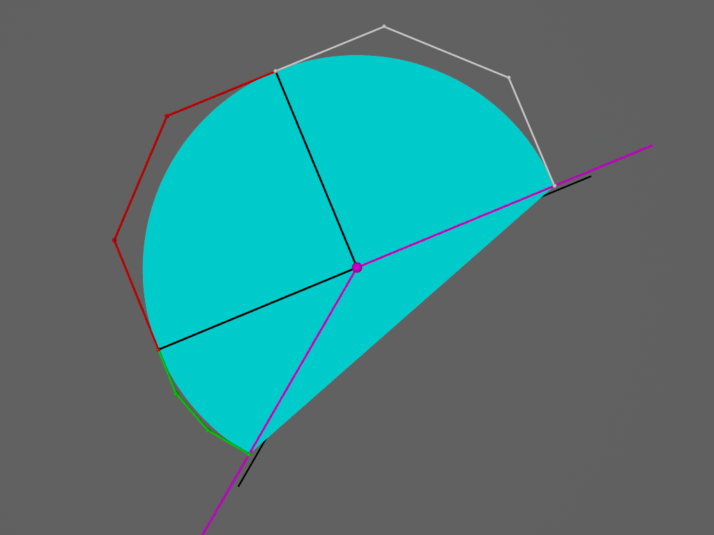
OK,  So after fixed the radial pigment pattern, I worked out a bunch of little
bits to pigment the arcs and recolor the chosen arcs.  Then I worked in the
linear bezier code, the segmented bezier arc code, played with the
directionality of the segments, got an array to collect all the data, and
started to tidy up the prism definition.

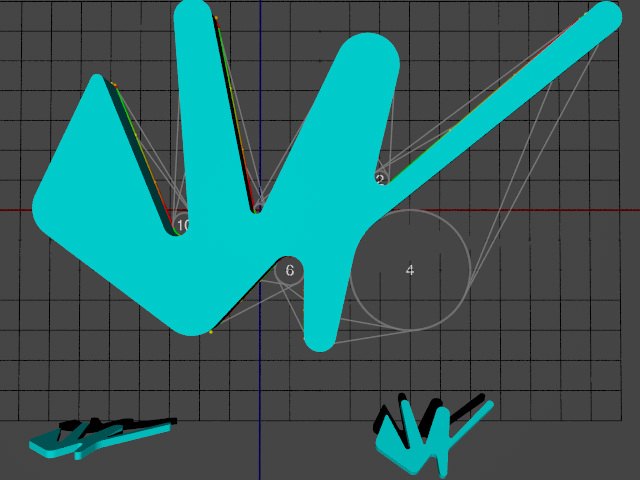
The path looks mostly ok - except that somehow I'm dropping a circle and its
tangents.   :|   And since something is amiss, the prism isn't closed, and so
there's no prism.

I will have to work that out - hopefully soon. So very very close.

Anyway:
Here's how it works:

First an array of circles is declared -
x,y,z of center, and radius
two more values for when I get around to polygonal pulleys,
and then which tangents and arcs to use, along with a directional adjustment for
each.


 #declare CircleArray = array [11][10]{
  { 0.00, 0,  0.00, 0.10,   0, 0,  _Red, _Fwd, _Blk, _Fwd},
  { 1.75, 0,  2.25, 0.50,   0, 0,  _Grn, _Fwd, _Wht, _Rev},
  { 2.00, 0,  0.50, 0.15,   0, 0,  _Red, _Fwd, _Blk, _Rev},
  { 5.50, 0,  3.00, 0.25,   0, 0,  _Grn, _Fwd, _Wht, _Rev},
  { 2.50, 0, -1.00, 1.00,   0, 0,  _Red, _Fwd, _Blk, _Fwd},
  { 1.00, 0, -2.00, 0.25,   0, 0,  _Grn, _Fwd, _Wht, _Fwd},
  { 0.50, 0, -1.00, 0.25,   0, 0,  _All, _Fwd, _All, _Fwd},
  {-1.00, 0, -1.50, 0.50,   0, 0,  _All, _Fwd, _All, _Fwd},
  {-3.00, 0,  0.00, 0.50,   0, 0,  _All, _Fwd, _All, _Rev},
  {-2.50, 0,  2.00, 0.10,   0, 0,  _All, _Fwd, _All, _Rev},
  {-1.25, 0, -0.25, 0.20,   0, 0,  _All, _Fwd, _All, _Fwd},
  //{-1.00, 0,  3.00, 0.30,   0, 0,  _Blu, _Fwd, _Blk, _Fwd},
  }


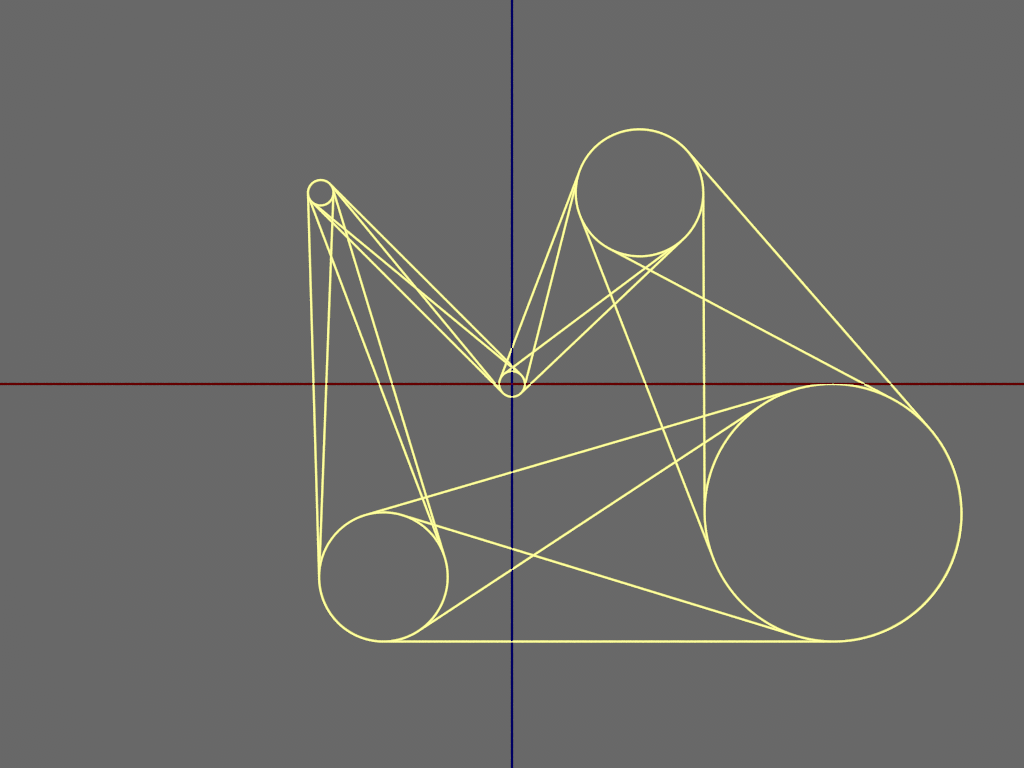
The circles and all of the tangents get drawn out, and then you use that first
render to choose the path.  Once a circle has two tangents chosen, there are now
endpoints for 2 arcs, and those arcs get colored.  Pick which arc you want, and
you get a continuous path, colored green-to-red start -to-finish.

Then a loop cranks through the circle array and assigns Bezier spline segments
to everything and writes that into an array.

Then a loop inside a prism declaration unwraps all of those points for the
prism.


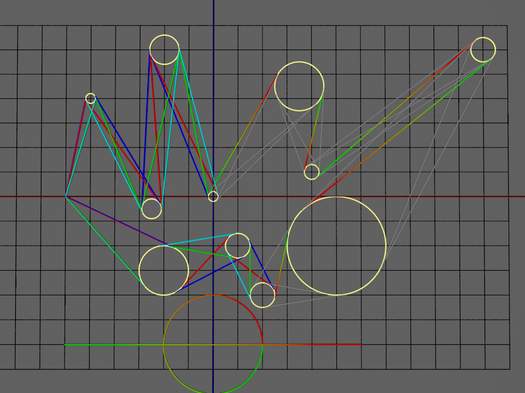
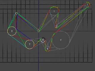
In the attached image, circles 0-5 all have the tangent and arc paths selected.
circle 6 has both tangents selected, but the arc path still isn't defined.
7, 8, and 9 are all in the initial stage.

And now to do more debugging.   :(


Post a reply to this message


Attachments:
Download 'serpentinebeltprism.png' (531 KB)

Preview of image 'serpentinebeltprism.png'
serpentinebeltprism.png


From: Bald Eagle
Subject: Re: Tangents with analytical geomtery
Date: 22 Oct 2019 21:00:01
Message: <web.5dafa52521826f334eec112d0@news.povray.org>
"Bald Eagle" <cre### [at] netscapenet> wrote:

> And now to do more debugging.   :(

After fixing some bad wrapping code and a few other small things, and adding a
new debugging array to track the joining of the Bezier segments, ....

WHEEEEE!


Post a reply to this message


Attachments:
Download 'serpentinebeltprism.png' (203 KB)

Preview of image 'serpentinebeltprism.png'
serpentinebeltprism.png


Goto Latest 10 Messages Next 8 Messages >>>

Copyright 2003-2023 Persistence of Vision Raytracer Pty. Ltd.