|
|
|
|
|
|
| |
| |
|
|
|
|
| |
| |
|
|
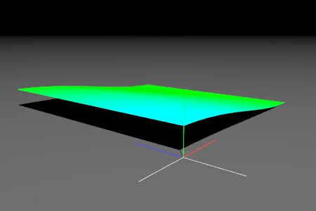
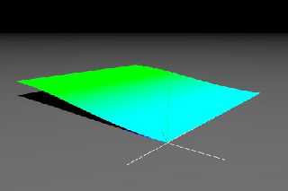
When I run the following the cylindrical pattern seems to be applied in
only the x dimension. Is it possible to apply it in x and z dimensions?
#macro MarkOrigin (Radius) //mark origin
cylinder { -100*y 0*y Radius
pigment { rgb .5 } finish { ambient .8} }
cylinder { -100*z 0*z Radius
pigment { rgb .5 } finish { ambient .8} }
cylinder { -100*x 0*x Radius
pigment { rgb .5 } finish { ambient .8} }
cylinder { 0*y 100*y Radius
pigment { rgb < 0, 1, 0 > } finish { ambient .8} }
cylinder { 0*z 100*z Radius
pigment { rgb < 0, 0, 1 > } finish { ambient .8} }
cylinder { 0*x 100*x Radius
pigment { rgb < 1, 0, 0 > } finish { ambient .8} }
#end
MarkOrigin (.4)
camera {
location <-120,60,-80>*3
look_at <250,0,250>
angle 55
right x*image_width/image_height
}
light_source {
0*x
color rgb 2.25
translate vrotate ( <0,0,-1200>, <60, 45, 0> )
}
plane {
y, 0
pigment {
rgb .1
}
finish {
ambient 0
diffuse .8
}
}
#local F_Terrain =
function {
pattern {
cylindrical
cubic_wave
}
}
#local Terrain =
height_field {
function 1000,1000 {
F_Terrain(x,y,z)
}
pigment {
function {
F_Terrain(x,y,z)
}
pigment_map {
[0 rgb Green]
[1 rgb Cyan]
}
}
scale <500, 50, 500 >
};
object { Terrain }
Post a reply to this message
Attachments:
Download 'img.1001.jpg' (9 KB)
Preview of image 'img.1001.jpg'
|
|
| |
| |
|
|
|
|
| |
| |
|
|
> function 1000,1000 {
> F_Terrain(x,y,z)
> }
This evaluates F_Terrain along the X-Y plane from <0,0,0> to <1,1,0>. Since
the cylinder goes along the y-axis (which ends up corresponding to the
z-axis in the height field), the height field only changes along the x-axis.
Two solutions:
- rotate your cylindrical pattern to face along the z-axis with rotate 90*x
- use the spherical pattern instead of cylindrical
- Slime
[ http://www.slimeland.com/ ]
Post a reply to this message
|
|
| |
| |
|
|
|
|
| |
| |
|
|
news:42371cd4@news.povray.org...
> When I run the following the cylindrical pattern seems to be applied in
> only the x dimension. Is it possible to apply it in x and z dimensions?
Hi
The cylindrical pattern creates a one unit radius cylinder along the Y axis.
and functions are evaluated on the x-y plane
so your pattern is parallel to the evaluation plane
so you could try something like
function {
pattern {
cylindrical
cubic_wave
rotate x*90
}
}
Marc
Post a reply to this message
|
|
| |
| |
|
|
|
|
| |
| |
|
|
news:4237206a$1@news.povray.org...
> > function 1000,1000 {
> > F_Terrain(x,y,z)
> > }
>
> This evaluates F_Terrain along the X-Y plane from <0,0,0> to <1,1,0>.
Since
> the cylinder goes along the y-axis (which ends up corresponding to the
> z-axis in the height field), the height field only changes along the
x-axis.
>
> Two solutions:
> - rotate your cylindrical pattern to face along the z-axis with rotate
90*x
> - use the spherical pattern instead of cylindrical
>
> - Slime
> [ http://www.slimeland.com/ ]
Sorry I was writing my post while you were posting :)
Marc
Post a reply to this message
|
|
| |
| |
|
|
|
|
| |
| |
|
|
Slime wrote:
>>function 1000,1000 {
>>F_Terrain(x,y,z)
>>}
>
>
> This evaluates F_Terrain along the X-Y plane from <0,0,0> to <1,1,0>. Since
> the cylinder goes along the y-axis (which ends up corresponding to the
> z-axis in the height field), the height field only changes along the x-axis.
>
> Two solutions:
> - rotate your cylindrical pattern to face along the z-axis with rotate 90*x
> - use the spherical pattern instead of cylindrical
>
> - Slime
> [ http://www.slimeland.com/ ]
>
>
From the docs:
3.5.11.10 Cylindrical
The cylindrical pattern creates a one unit radius cylinder along the Y
axis. It is computed by: value = 1.0-min(1, sqrt(X^2 + Z^2)) It starts
at 1.0 at the origin and decreases to a minimum value of 0.0 as it
approaches a distance of 1 unit from the Y axis.
Also, Why does the pigment behave like I would expect.
Post a reply to this message
|
|
| |
| |
|
|
|
|
| |
| |
|
|
news:423730c7$1@news.povray.org...
> Also, Why does 'not' the pigment behave like I would expect.
the pigment behaves like you would expect
but the image function evaluation is done on the x-y plane not ont the x-z
plane!
so you have to follow Slime's advice: either rotate your pattern by x*90 or
use spherical pattern
Marc
Post a reply to this message
|
|
| |
| |
|
|
|
|
| |
| |
|
|
Marc Jacquier wrote:
> news:423730c7$1@news.povray.org...
>
>>Also, Why does 'not' the pigment behave like I would expect.
>
> the pigment behaves like you would expect
> but the image function evaluation is done on the x-y plane not ont the x-z
> plane!
> so you have to follow Slime's advice: either rotate your pattern by x*90 or
> use spherical pattern
>
> Marc
>
>
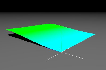
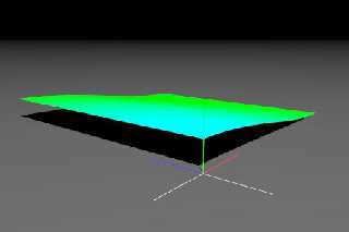
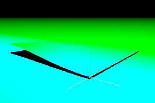
Yes I see that that works except the effect seems to translate by z*1
but I've got to say, for me this is all completely counter intuitive.
Whether I use it for a pigment or for a hf I picture the function, as
described in the docs as a sort of column along the y axis such that any
point on the y xis would return a value of 1, any value at x=1 and z=0
would return 0 for all values of y, etc. That seems to happen if I use
the function in a pigment whether I rotate or not. When the pattern is
used in a hf it seems to act like it is a cylinder along the y=-1 axis
that is then rotated? Forgive me if I am being a pest. I really am
having trouble picturing this. But I also had similar misunderstandings
when using the wood pattern. So I truly believe you guys are all able
to picture something that I am just not getting lol.
Post a reply to this message
Attachments:
Download 'img.1002.jpg' (9 KB)
Preview of image 'img.1002.jpg'
|
|
| |
| |
|
|
|
|
| |
| |
|
|
> Yes I see that that works except the effect seems to translate by z*1
> but I've got to say, for me this is all completely counter intuitive.
> Whether I use it for a pigment or for a hf I picture the function, as
> described in the docs as a sort of column along the y axis such that any
> point on the y xis would return a value of 1, any value at x=1 and z=0
> would return 0 for all values of y, etc. That seems to happen if I use
> the function in a pigment whether I rotate or not.
That is all correct.
The thing is, when you use the function 1000,1000 {...} syntax, it generates
a 1000x1000 image from the pattern. However, it does not know *how* this
image is going to be used! When images are loaded from files (with the
syntax tga "myimage.tga"), they are placed vertically, covering the area
from <0,0,0> to <1,1,0> and stretching in the z direction. So it makes sense
that when the function width,height syntax is used to *generate* an image,
it samples from that area also. It doesn't know that you're going to take
that image and use it in a height field, so it doesn't know that it would be
more convenient to sample from <0,0,0> to <1,0,1>.
So, you have to prepare your function to be sampled from the region <0,0,0>
to <1,1,0>, and recognize that after that sampling is done, the data will be
used in a different orientation. Kind of like the sampled area of the
texture were rotate 90 degrees around the x-axis, and then raised along the
y-axis depending on its value at a given point.
What you want is a cross-section of the cylindrical pattern along the x-z
plane. But function width,height samples along the x-y plane, so you have to
take your pattern and rotate it around the x-axis by 90 degrees so that the
cross section you're interested in lies along the x-y plane. That's where it
is then sampled, and that data is turned into a height field.
- Slime
[ http://www.slimeland.com/ ]
Post a reply to this message
|
|
| |
| |
|
|
|
|
| |
| |
|
|
In article <4237206a$1@news.povray.org>, "Slime" <fak### [at] email address>
wrote:
> Two solutions:
> - rotate your cylindrical pattern to face along the z-axis with rotate 90*x
> - use the spherical pattern instead of cylindrical
Another solution: do the rotation in the call to the function. It's a 90
degree rotation around one axis, so just swap two coordinates and negate
one of them. Since you're generating an image for the height field, it's
even easier to figure out...function images are sampled from the xy
plane, the height field uses the image for the xz plane.
function 1000, 1000 {F_Terrain(x, 0, y)}
--
Christopher James Huff <cja### [at] gmailcom>
POV-Ray TAG: <chr### [at] tagpovrayorg>
http://tag.povray.org/ address>
wrote:
> Two solutions:
> - rotate your cylindrical pattern to face along the z-axis with rotate 90*x
> - use the spherical pattern instead of cylindrical
Another solution: do the rotation in the call to the function. It's a 90
degree rotation around one axis, so just swap two coordinates and negate
one of them. Since you're generating an image for the height field, it's
even easier to figure out...function images are sampled from the xy
plane, the height field uses the image for the xz plane.
function 1000, 1000 {F_Terrain(x, 0, y)}
--
Christopher James Huff <cja### [at] gmailcom>
POV-Ray TAG: <chr### [at] tagpovrayorg>
http://tag.povray.org/
Post a reply to this message
|
|
| |
| |
|
|
|
|
| |
| |
|
|
Slime wrote:
Thanks for that Slime. And now I understand why the apparent difference
between the behavior of the pigment and the hf was faking me out. The
pigment was being "rotated" too, but its intersection with the surface
just happened to mimic somewhat, what the unrotated pattern might also do.
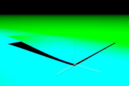
Now I just have to try and understand why the apparent center of the
cylinder in the cylindrical pattern seems to be at x=0 z=1
Post a reply to this message
Attachments:
Download 'img.1003.jpg' (10 KB)
Preview of image 'img.1003.jpg'
|
|
| |
| |
|
|
|
|
| |
|
|