|
|
|
|
|
|
| |
| |
|
|
|
|
| |
| |
|
|
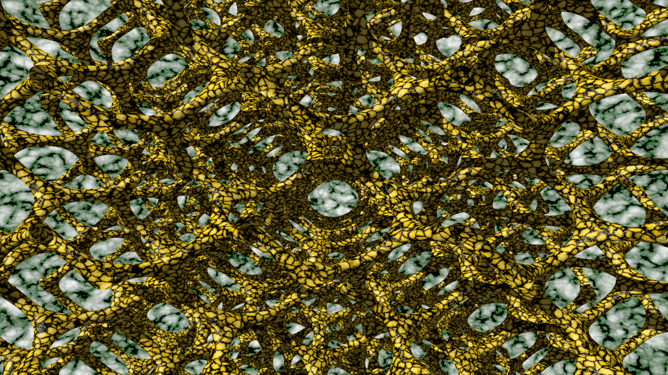
Nothing really original here, but decided to post this here [with (yet another)
question] since I always like to discover new and beautiful things in the image
digest.
Isosurface equation modified for use in SDL from:
http://www.aleph.se/Nada/Ray/matlabobj.html
which references:
http://www.msri.org/publications/sgp/SGP/indexc.html
This took 43 min on my laptop. I looked it over, and thought that maybe I
could approximate it with blobs - but I need a 3D matrix of points - probably
like the coordinates of the carbons in a diamond crystal.
My question here is:
Is there a good way to "get" such a matrix of 3D points from patterns in
POV-Ray? I don't quite understand how the infinite patterns for pigments are
generated, stored, and used internally.
It would be nice to be able to generate an array that was composed of points
inside of a contained_by{} box by somehow sampling that space and storing any
value that's 0, 1, 0.5 - whatever it would be.
I still don't even understand how crackle is generated - Voronoi / Delaunay -
yeah, yeah - the details still stump me, so this is probably a poorly formulated
question, but hopefully someone gets the gist of it and can offer some
inspiration, pseudo-code, links, or .pov files as a starting point :)
Post a reply to this message
Attachments:
Download 'isosurfacenetwork.png' (2288 KB)
Preview of image 'isosurfacenetwork.png'
|
|
| |
| |
|
|
|
|
| |
| |
|
|
Am 16.07.2016 um 18:24 schrieb Bald Eagle:
> Is there a good way to "get" such a matrix of 3D points from patterns in
> POV-Ray? I don't quite understand how the infinite patterns for pigments are
> generated, stored, and used internally.
For most patterns, the principle is quite simple: To compute the pattern
value at a particular point in space, a pattern-specific algorithm takes
the coordinates of the points, does some mathematical operations on
them, and spits out a result. So in essence, each pattern is a
mathematical formula.
Where (pseudo-) randomness is involved, that's usually based on Perlin
noise (or a similar mechanism). In contrast to a classic sequential
pseudo-random number generator, where you need to pull the values in a
particular sequence to reproduce the same results, this mechanism can
reproducibly compute a pseudo-random-ish value for any given point in 3D
space, without having to look at any other point in space.
It may be surprising at first to realize that, in theory, this approach
can also be used to implement a voroni pattern, provided you agree to
certain non-random properties in the "seed points" of the pattern:
- In POV-Ray's voroni pattern, if you subdivide 3D space into 1x1x1
cubes (aligned with the coordinate axes, and <0,0,0> coinciding with a
cube corner), there will be exactly one "seed point" in each such cube.
This allows to evaluate the voroni pattern for any given point as follows:
- Take the coordinates of the point in question.
- From these, compute integer corners of the 1x1x1 cube in question.
- From these integer coordinates, compute three pseudo-random-ish values
and use them as the "seed point" for this cube.
- Likewise, compute the "seed points" of nearby cubes that could,
depending on their position, affect the pattern result.
- From all the potentially relevant "seed point" coordinates, compute
the pattern value for the point in question.
Theoretically, this is all the "magic" in POV-Ray's crackle pattern. In
practice, POV-Ray implements a way to speed up computation, by
maintaining a cache of already-computed "seed points".
> It would be nice to be able to generate an array that was composed of points
> inside of a contained_by{} box by somehow sampling that space and storing any
> value that's 0, 1, 0.5 - whatever it would be.
An algorithm to systematically search for the cell centers within each
1x1x1 cube should be comparatively simple to implement:
- Use a crackle pattern with `form <1,0,0>` and `metric 2`, essentially
giving you the distance to the closest seed point.
- In most cases, the seed point closest to the center of the 1x1x1 cube
in question will be that cube's own seed point; in that case, finding
the seed point is just a matter of evaluating the pattern's values at
four well-chosen points close to the center, and from those values
computing the distance and direction of the seed point.
- Once you have computed the position of the seed point, verify that
it's inside the 1x1x1 cube and that the pattern evaluates to 0 there
(give or take a small margin of error).
- If that is not the case, some other seed point is closer to the center
than the cube's own and will have messed up your results; in that case,
you'll need to repeat the process at other regions of the cube; my guess
is that the centers of the octants would be the next best choices. It
might also be worth figuring out where that interfering seed point is,
and probing the 1x1x1 cube reasonably far from it.
Alternatively, you could try to re-implement POV-Ray's "seed point"
generation algorithm in SDL.
Post a reply to this message
|
|
| |
| |
|
|
|
|
| |
| |
|
|
clipka <ano### [at] anonymous org> wrote:
> Am 16.07.2016 um 18:24 schrieb Bald Eagle:
>
> > Is there a good way to "get" such a matrix of 3D points from patterns in
> > POV-Ray? I don't quite understand how the infinite patterns for pigments are
> > generated, stored, and used internally.
>
> For most patterns, the principle is quite simple: To compute the pattern
> value at a particular point in space, a pattern-specific algorithm takes
> the coordinates of the points, does some mathematical operations on
> them, and spits out a result. So in essence, each pattern is a
> mathematical formula.
I got that - after working with SDL for the past several years and reading a
gazillion posts and {gasp!} the documentation, this seems to be the way most
everything is determined - pigment patterns, textures, etc.
I decided to try to work out how to plot a 3D network of points based on what is
presented here:
https://en.wikipedia.org/wiki/Diamond_cubic#Mathematical_structure
It's hard to tell how poorly written this is until you try to actually use it
for anything. All of the statements are (probably) technically correct and very
specifically factual, but they don't really get you anywhere, and it's very
confusing to follow once you try to get at the meat of it.
This didn't really seem to work so well:
#declare Basis = array[8] {<0, 0, 0>, <0, 2, 2>, <2, 0, 2>, <2, 2, 0>, <3, 3,
3>, <3, 1, 1>, <1, 3, 1>, <1, 1, 3>};
#declare B = dimension_size (Basis, 1);
#declare Multipliers = array[7] {<4, 0, 0>, <0, 4, 0>, <0, 0, 4>, <4, 4, 0>, <4,
0, 4>, <0, 4, 4>, <4, 4, 4>};
#declare M = dimension_size (Multipliers, 1);
#for (i, 0, 4)
#for (j, 0, M-1)
#for (k, 0, B-1)
sphere {Basis[k]+(Multipliers[j]*i) 0.5 pigment {Green} }
// {Be sure to include debug.inc file!}
#debug concat( " i = ", str (i, 3, 1), " j = ", str (j, 3, 1), " k = ", str (k,
3, 1), " \n")
#debug concat( "Basis[k]: ", vstr (3, Basis[k], ", ", 2, 0), " Multipliers[j]:
", vstr (3, Multipliers[j], ", ", 2, 0), " (Multipliers[j]*i)", vstr (3,
(Multipliers[j]*i), ", ", 2, 0), "\n" )
#debug concat( "Sphere at: ", vstr (3, Basis[k]+(Multipliers[j]*i), ", ", 2, 0),
" \n\n")
#end
#end // end j
#end // end i org> wrote:
> Am 16.07.2016 um 18:24 schrieb Bald Eagle:
>
> > Is there a good way to "get" such a matrix of 3D points from patterns in
> > POV-Ray? I don't quite understand how the infinite patterns for pigments are
> > generated, stored, and used internally.
>
> For most patterns, the principle is quite simple: To compute the pattern
> value at a particular point in space, a pattern-specific algorithm takes
> the coordinates of the points, does some mathematical operations on
> them, and spits out a result. So in essence, each pattern is a
> mathematical formula.
I got that - after working with SDL for the past several years and reading a
gazillion posts and {gasp!} the documentation, this seems to be the way most
everything is determined - pigment patterns, textures, etc.
I decided to try to work out how to plot a 3D network of points based on what is
presented here:
https://en.wikipedia.org/wiki/Diamond_cubic#Mathematical_structure
It's hard to tell how poorly written this is until you try to actually use it
for anything. All of the statements are (probably) technically correct and very
specifically factual, but they don't really get you anywhere, and it's very
confusing to follow once you try to get at the meat of it.
This didn't really seem to work so well:
#declare Basis = array[8] {<0, 0, 0>, <0, 2, 2>, <2, 0, 2>, <2, 2, 0>, <3, 3,
3>, <3, 1, 1>, <1, 3, 1>, <1, 1, 3>};
#declare B = dimension_size (Basis, 1);
#declare Multipliers = array[7] {<4, 0, 0>, <0, 4, 0>, <0, 0, 4>, <4, 4, 0>, <4,
0, 4>, <0, 4, 4>, <4, 4, 4>};
#declare M = dimension_size (Multipliers, 1);
#for (i, 0, 4)
#for (j, 0, M-1)
#for (k, 0, B-1)
sphere {Basis[k]+(Multipliers[j]*i) 0.5 pigment {Green} }
// {Be sure to include debug.inc file!}
#debug concat( " i = ", str (i, 3, 1), " j = ", str (j, 3, 1), " k = ", str (k,
3, 1), " \n")
#debug concat( "Basis[k]: ", vstr (3, Basis[k], ", ", 2, 0), " Multipliers[j]:
", vstr (3, Multipliers[j], ", ", 2, 0), " (Multipliers[j]*i)", vstr (3,
(Multipliers[j]*i), ", ", 2, 0), "\n" )
#debug concat( "Sphere at: ", vstr (3, Basis[k]+(Multipliers[j]*i), ", ", 2, 0),
" \n\n")
#end
#end // end j
#end // end i
Post a reply to this message
|
|
| |
| |
|
|
|
|
| |
| |
|
|
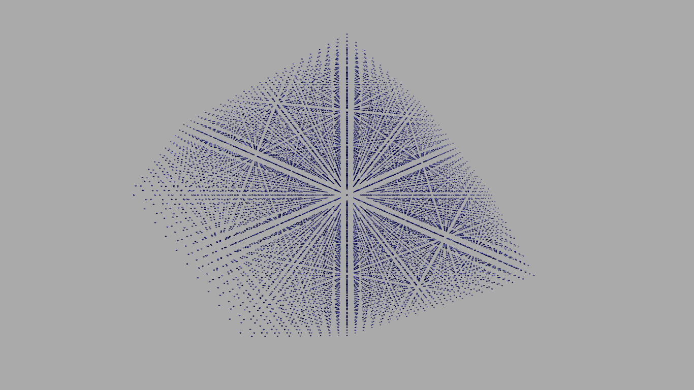
Tried a second method based on 4D vectors converted to 3D coordinates.
I get output that superficially appears to be valid, but I have problems when
adding bonds to "the 4 nearest neighbors" - it just seems like it comes out
wrong.
I added some checks to filter out invalid endpoint coordinates, but that didn't
seem to fix things.
Change space and iterations to increase or decrease the number of spheres.
--------------------------------------------------------------------------
#declare ShowCylinders = false;
#declare Space = 10;
#declare Iterations = 10;
#for (d, -Iterations, Iterations)
#for (a, -Space, Space)
#for (b, -Space, Space)
#for (c, -Space, Space)
#if ( (a+b+c)=0 | (a+b+c)=1)
#declare X = (a + b - c - d);
#declare Y = (a - b + c - d);
#declare Z = (-a + b + c - d);
//#debug concat( " X = ", str(X, 3, 1), " Y = ", str(Y, 3, 1), " Z = ",
str(Z, 3, 1), "\n")
sphere {<X, Y, Z> 0.125 texture {pigment {Blue*0.4} finish {specular 0.6}}
}
//############################################################################################################
#if (ShowCylinders)
// The four nearest neighbors of each point may be obtained, in this
coordinate system,
// by adding one to each of the four coordinates, or by subtracting one
from each of the four coordinates,
// accordingly as the coordinate sum is zero or one.
#declare FourD = array[4] {a, b, c, d}
#declare NewPoint = array[4] {0, 0, 0, 0}
#for (Adjustment, 0, 3)
#for (Power, 1, 2)
#declare Factor = pow (-1, Adjustment);
#for (Coordinate, 0, 3)
#if (Coordinate = Adjustment)
#declare NewPoint[Coordinate] = FourD[Coordinate]+Factor;
#else
#declare NewPoint[Coordinate] = FourD[Coordinate];
#end // end if
#end // for Coordinate
#declare a2 = NewPoint[0];
#declare b2 = NewPoint[1];
#declare c2 = NewPoint[2];
#declare d2 = NewPoint[3];
#if ( (a2+b2+c2)=0 | (a2+b2+c2)=1)
#declare X2 = ( a2 + b2 - c2 - d2);
#declare Y2 = ( a2 - b2 + c2 - d2);
#declare Z2 = (-a2 + b2 + c2 - d2);
#if (X=X2 | Y=Y2 | Z=Z2)
#else
cylinder {<X, Y, Z>, <X2, Y2, Z2>, 0.0725 pigment {Red}}
#end // end degenerate cylinder check
#end // end a2+b2+c2 check
#end // end for Power
#end // end for Adjustment
#end // end if ShowCylinders
//############################################################################################################
#end // end if
#end // end for c
#end // end for b
#end // end for a
#end // end for d
Post a reply to this message
Attachments:
Download 'diamondstructure.png' (390 KB)
Preview of image 'diamondstructure.png'
|
|
| |
| |
|
|
|
|
| |
| |
|
|
Am 17.07.2016 um 20:37 schrieb Bald Eagle:
> I decided to try to work out how to plot a 3D network of points based on what is
> presented here:
> https://en.wikipedia.org/wiki/Diamond_cubic#Mathematical_structure
I'm not really sure what that has to do with the crackle pattern.
Post a reply to this message
|
|
| |
| |
|
|
|
|
| |
| |
|
|
clipka <ano### [at] anonymousorg> wrote:
> I'm not really sure what that has to do with the crackle pattern.
It has to do with the generation of a defined 3D network of points - in general;
any network, potentially infinite, based on math.
As you can see above, the diamond pattern was the first I mentioned, and crackle
was another. Specific instances of a more general interest.
I know others have mentioned in the past wanting to gain direct access to the
seed points for crackle, and I think that "direct access" or access to a copy of
most of the simple infinite patterns would be an extremely useful thing.
I tend to zig and zag for a while until can get some perspective and inspiration
and home in on some ideological asymptote.
Crackle just sort of makes my head hurt, especially in 3D, and I didn't want to
_start_ with that. (Plus, it is HOT here - whew!) Diamond is defined, rigid,
regular, and there was some discussion about calculating the position of any
point in the network. Coupled with
http://www.sas.upenn.edu/~vnanda/source/rwalk.cpp , I thought I'd take a stab
at that.
Apologies for any confusion.
Post a reply to this message
|
|
| |
| |
|
|
|
|
| |
| |
|
|
Am 18.07.2016 um 13:11 schrieb Bald Eagle:
> I know others have mentioned in the past wanting to gain direct access to the
> seed points for crackle, and I think that "direct access" or access to a copy of
> most of the simple infinite patterns would be an extremely useful thing.
I can see what you mean by "direct accesss to the seed points for
crackle", but what would "'direct access' or access to a copy of" any of
the "simple infinite patterns" be in this context?
Post a reply to this message
|
|
| |
| |
|
|
|
|
| |
| |
|
|
clipka <ano### [at] anonymousorg> wrote:
> I can see what you mean by "direct accesss to the seed points for
> crackle", but what would "'direct access' or access to a copy of" any of
> the "simple infinite patterns" be in this context?
brick, cells, checker, gradient, hexagon, spiral, square, triangular, wood
perhaps any of the tilings or pavements
any crystal structure - real or theoretical
I'm just thinking from the perspective of ready-made subdivisions of 3D space,
especially in the context of individual points.
That would allow the rapid generation of wireframe "boxes" of all sorts of
shapes, placement of objects and light sources along grid intersections that are
not necessarily rectangular, they would form the basis of user-defined patterns
since they would act as a sort of "graph paper", etc.
They could also form the basis for mapping or subdividing the surface of an
object - picture lines or cones or boxes radiating out from the interior of an
object like a sphere or a box. The interior point is presumably known /
selected, and then FROM that point, you have a network of points to "draw out"
TO.
How will this work? What will people use it for?
How the heck do I know? I just know that if someone makes a tool, then the
creative people here will pick it up and play with it in ways we could never
predict. I just think such a set of pattern-point tools would be useful and
inspiring, and labor-saving.
They don't necessarily have to be "internal" to POV-Ray - they could be macros
or formulas, or anything the user has direct access to and possibly control
over.
Just an idea.
Post a reply to this message
|
|
| |
| |
|
|
|
|
| |
| |
|
|
Am 18.07.2016 um 16:20 schrieb Bald Eagle:
> clipka <ano### [at] anonymousorg> wrote:
>
>> I can see what you mean by "direct accesss to the seed points for
>> crackle", but what would "'direct access' or access to a copy of" any of
>> the "simple infinite patterns" be in this context?
>
> brick, cells, checker, gradient, hexagon, spiral, square, triangular, wood
> perhaps any of the tilings or pavements
I can imagine what patterns you have in mind, but I still only have a
vague idea what "direct access" you envision for them.
> any crystal structure - real or theoretical
That's a lot, I guess ;)
Obviously, some of them are /not/ available as POV-Ray patterns, so what
about them?
> I'm just thinking from the perspective of ready-made subdivisions of 3D space,
> especially in the context of individual points.
>
> That would allow the rapid generation of wireframe "boxes" of all sorts of
> shapes, placement of objects and light sources along grid intersections that are
> not necessarily rectangular, they would form the basis of user-defined patterns
> since they would act as a sort of "graph paper", etc.
The problem there is that, except for the crackle pattern, the "nodes"
of the patterns provided by POV-Ray don't exist /a priori/; rather, they
emerge from the way the pattern value is computed from individual
points: Where there's a discontinuity in value of nearby points, there's
a node; where there is only a gradual change, there isn't.
Various of the patterns you mentioned don't even have point-like nodes,
and just have line-like or surface-like discontinuities. The wood
pattern is one such example: It has one central line-like discontinuity,
with concentric cylinder-like discontinuities at regular distances.
And even when patterns do exhibit point-like nodes, any application of
even the slightest turbulence would make it impossible to identify their
effective resulting location: "backtracking" POV-Ray's turbulence warp
is, to my knowledge, not feasible.
> They could also form the basis for mapping or subdividing the surface of an
> object - picture lines or cones or boxes radiating out from the interior of an
> object like a sphere or a box. The interior point is presumably known /
> selected, and then FROM that point, you have a network of points to "draw out"
> TO.
Now you again have me at the disadvantage of not understanding what you
mean :)
> How will this work? What will people use it for?
> How the heck do I know?
I guess that's the crux of the matter ;)
> I just know that if someone makes a tool, then the
> creative people here will pick it up and play with it in ways we could never
> predict. I just think such a set of pattern-point tools would be useful and
> inspiring, and labor-saving.
>
> They don't necessarily have to be "internal" to POV-Ray - they could be macros
> or formulas, or anything the user has direct access to and possibly control
> over.
That may be a reasonable approach. Aside from the crackle pattern, I
don't think it would be reasonable to even attempt to implement such
stuff in POV-Ray proper.
Which of course puts the responsibility for picking up and implementing
your idea into the hands of the POV-Ray community as a whole, and I
myself can conveniently back out of the topic ;)
Post a reply to this message
|
|
| |
| |
|
|
|
|
| |
| |
|
|
On 07/18/2016 04:20 PM, Bald Eagle wrote:
...
> I'm just thinking from the perspective of ready-made subdivisions of 3D space,
> especially in the context of individual points.
...
Have you looked at the source code for these images ?
(It's on my webpage.)
http://hof.povray.org/Isosurface-Cubic_Space_Division.html
http://hof.povray.org/Isosurface-Sombrero.html
There are more images made with similar techniques in this folder:
http://subcube.com/POV-Ray_Images/
E.g.:
Isosurface_Sphere_Inversion.jpg
Isosurface_Torus_Grid.jpg
Isosurface_Circle_Inversion.jpg
Isosurfaces_Escher_Grid.jpg
Isosurface_Construction.jpg
Isosurfaces_Blobbing.jpg
Isosurface_Crackle_Pattern.jpg
I'm sure that it can be be done with non rectangular/cubic space
divisions as well.
R Suzuki once made some interesting (but quite complex) isosurface
macros that might be relevant:
From: R Suzuki
Subject: Example of Rope Macro
Date: 22 Jan 2002 09:52:27
http://news.povray.org/povray.binaries.images/thread/%3C3c4d365b%40news.povray.org%3E/
From: R Suzuki
Subject: Rope Macro
Date: 22 Jan 2002 09:49:44
http://news.povray.org/povray.binaries.scene-files/thread/%3C3c4d35b8%40news.povray.org%3E/
See his attached rope.inc file for the macros.
--
Tor Olav
http://subcube.com
Post a reply to this message
|
|
| |
| |
|
|
|
|
| |
|
|