|
|
|
|
|
|
| |
| |
|
|
|
|
| |
| |
|
|
On 23/05/2022 1:08 am, Aj wrote:
> Hello everyone,
>
> I created a spline object using the following code, but I could not get the
> proper camera position. I was wondering if there is some systematic way to
> figure out the camera position, and angle and look at vectors for a given shape.
> Or is it just trial and error? Can someone please help me to get the proper
> camera setup so as to obtain the figure attached:
>
>
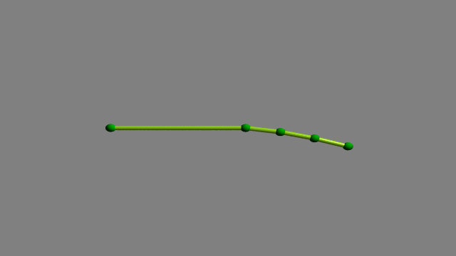
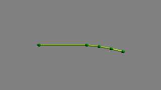
The points in your sphere_sweep don't plot the figure in the screen
shot, the points form a more or less straight line in the z direction.
(1.png) (Points 5 & 6 are the same.)
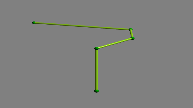
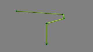
Looking again at the screen shot, I notice that the 3 axes are at
different scales. If I apply scaling and rotation to the points I can
get something like your figure. Scale = <200,10,1> rotate<0,90,0> (2.png)
Note that I have moved the camera to <0,0,-200>, looking at <0,0,0>. I
find it easier to keep track of x,y,z if the camera is in the minus z
position.
If you want a point for the camera to look at, you can find the mean
center of your plot thus:
#declare Thing_max = max_extent(Thing);
#declare Thing_min = min_extent(Thing);
#declare Thing_centre = (max_extent(Thing) + min_extent(Thing))/2;
(Red sphere)
---------------------------------------------------------------
#include"colors.inc"
camera {
//location <-0.0872 , -1.8850 , 4.8301 >*3.5
location <0,0,-200>
look_at <0,0,0>
angle 22
}
light_source { <100,100,-100> color rgb<1,1,1> }
background {color rgb<0.5,0.5,0.5> }
#declare Scale = <200,10,1>;
//#declare Scale = <1,1,1>;
#declare P01 = Scale*< 0, 0, -20>;
#declare P02 = Scale*< 2.583e-09,-2.7093e-08, 3>;
#declare P03 = Scale*< 0.075646, -0.91834, 8.9288>;
#declare P04 = Scale*< 0.076898, -2.3756, 14.7492>;
#declare P05 = Scale*<-0.15231, -4.2038, 20.4593>;
#declare P06 = Scale*<-0.15231, -4.2038, 20.4593>;
#declare Thing = union{
sphere{P01 0.9 pigment{rgb<0,1,0>}}
sphere{P02 0.9 pigment{rgb<0,1,0>}}
sphere{P03 0.9 pigment{rgb<0,1,0>}}
sphere{P04 0.9 pigment{rgb<0,1,0>}}
sphere{P05 0.9 pigment{rgb<0,1,0>}}
sphere{P06 0.5 pigment{rgb<0,1,0>}}
sphere_sweep {
//b_spline
linear_spline
6,
P01,0.5,
P02,0.5,
P03,0.5,
P04,0.5,
P05,0.5,
P06,0.5
tolerance 0.1
texture{ pigment{ color rgb<0.69,0.99,0.15>}
finish { phong 1
ambient 0.3
}
}
//scale<2,2,0.35> rotate<-90,0,0> translate<0,-2,3>
}
//rotate<0,90,0>
rotate<-90,0,0>
}
#declare Thing_max = max_extent(Thing);
#declare Thing_min = min_extent(Thing);
#declare Thing_centre = (max_extent(Thing) + min_extent(Thing))/2;
sphere{Thing_centre, 1.5 pigment{rgb<1,0,0>} rotate<0,360*clock,0>}
//box{Thing_min, Thing_max pigment{rgbt<1,0,0,0.8>}
rotate<0,360*clock,0>}
object{Thing rotate<0,360*clock,0>}
Post a reply to this message
Attachments:
Download '1.png' (7 KB)
Download '2.png' (10 KB)
Preview of image '1.png'
Preview of image '2.png'
|
|
| |
| |
|
|
|
|
| |
| |
|
|
"Bald Eagle" <cre### [at] netscape net> wrote:
> "Aj" <nomail@nomail> wrote:
> > Hello everyone,
> >
> > I created a spline object using the following code, but I could not get the
> > proper camera position. I was wondering if there is some systematic way to
> > figure out the camera position, and angle and look at vectors for a given shape.
>
> Yours might be easier, given that you have the grid locations on axes to guide
> you.
>
> Try imagining how the image you posted could be rotated in reverse to straighten
> the axes in the camera frustrum, and use those transforms on the object.
> The actual camera position might be a bit of trial and error to get exactly
> right.
>
> The look_at position might be obtained by extrapolating the x/z grid ticks and
> applying that inverse rotate transform.
>
> Maybe Francois LeCoat has a clever solution, as this seems right up his alley,
> or TOK has some words/code lines of wisdom to offer.
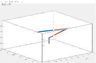
Hehe, there you tempted me to have a look at this.
I opened the screenshot in gimp and copied the 3 axes around to check if the
camera used could be a orthographic camera. It seems so.
See the attached image.
And here's some code ;-)
// ===== 1 ======= 2 ======= 3 ======= 4 ======= 5 ======= 6 ======= 7
// Render options: +w640 +h480 +a0.3
#version 3.7;
global_settings { assumed_gamma 1.0 }
#include "colors.inc"
default {
texture {
pigment { color White }
finish {
diffuse 0
emission color White
}
}
}
// ===== 1 ======= 2 ======= 3 ======= 4 ======= 5 ======= 6 ======= 7
// Extreme values on the axes
#declare XN0 = -14.00; // *1e-3
#declare XP0 = +4.00; // *1e-3
#declare YN0 = 0.00; // *1e-3 ?
#declare YP0 = +1.00; // *1e-3 ?
#declare ZN0 = -0.25; // *1e-3 ?
#declare ZP0 = +0.05; // *1e-3 ?
// Divisions on the axes
#declare DivX0 = 2.00; // *1e-3
#declare DivY0 = 0.20; // *1e-3 ?
#declare DivZ0 = 0.05; // *1e-3 ?
// Number of divisions from the center of
// each axis to the axis endpoints
#declare XN1 = -4.5;
#declare XP1 = +4.5;
#declare YN1 = -2.5;
#declare YP1 = +2.5;
#declare ZN1 = -3.0;
#declare ZP1 = +3.0;
// These were found by trail and error
#declare ScaleX = 1.10;
#declare ScaleY = 0.96;
#declare ScaleZ = 1.64;
#declare FnX =
function(x) {
ScaleX*(XN1 + (x - XN0)/(XP0 - XN0)*(XP1 - XN1))
}
;
#declare FnY =
function(y) {
ScaleY*(YN1 + (y - YN0)/(YP0 - YN0)*(YP1 - YN1))
}
;
#declare FnZ =
function(z) {
ScaleZ*(ZN1 + (z - ZN0)/(ZP0 - ZN0)*(ZP1 - ZN1))
}
;
#declare XN2 = FnX(XN0);
#declare XP2 = FnX(XP0);
#declare YN2 = FnY(YN0);
#declare YP2 = FnY(YP0);
#declare ZN2 = FnZ(ZN0);
#declare ZP2 = FnZ(ZP0);
#declare pNNN = <XN2, YN2, ZN2>;
#declare pPNN = <XP2, YN2, ZN2>;
#declare pPNP = <XP2, YN2, ZP2>;
#declare pNNP = <XN2, YN2, ZP2>;
#declare pNPN = <XN2, YP2, ZN2>;
#declare pPPN = <XP2, YP2, ZN2>;
#declare pPPP = <XP2, YP2, ZP2>;
#declare pNPP = <XN2, YP2, ZP2>;
#declare CylinderRadius = 0.02;
union {
union {
cylinder { pNNN, pPNN, CylinderRadius }
cylinder { pNNP, pPNP, CylinderRadius }
cylinder { pNPN, pPPN, CylinderRadius }
cylinder { pNPP, pPPP, CylinderRadius }
pigment { color Red }
}
union {
cylinder { pNNN, pNPN, CylinderRadius }
cylinder { pPNN, pPPN, CylinderRadius }
cylinder { pPNP, pPPP, CylinderRadius }
cylinder { pNNP, pNPP, CylinderRadius }
pigment { color Green }
}
union {
cylinder { pPNN, pPNP, CylinderRadius }
cylinder { pNNN, pNNP, CylinderRadius }
cylinder { pPPN, pPPP, CylinderRadius }
cylinder { pNPN, pNPP, CylinderRadius }
pigment { color Blue }
}
}
#declare TickRadius = 2*CylinderRadius;
#declare TicksX =
union {
#for (X, XN0 + DivX0, XP0 - DivX0, DivX0)
sphere { FnX(X)*x, TickRadius }
#end // for
}
#declare TicksY =
union {
#for (Y, YN0 + DivY0, YP0 - DivY0, DivY0)
sphere { FnY(Y)*y, TickRadius }
#end // for
}
#declare TicksZ =
union {
#for (Z, ZN0 + DivZ0, ZP0 - DivZ0, DivZ0)
sphere { FnZ(Z)*z, TickRadius }
#end // for
}
union {
object {
TicksX
translate <0, YN2, ZN2>
}
object {
TicksX
translate <0, YP2, ZN2>
}
object {
TicksX
translate <0, YP2, ZP2>
}
object {
TicksX
translate <0, YN2, ZP2>
}
pigment { color White }
}
union {
object {
TicksY
translate <XN2, 0, ZN2>
}
object {
TicksY
translate <XP2, 0, ZN2>
}
object {
TicksY
translate <XP2, 0, ZP2>
}
object {
TicksY
translate <XN2, 0, ZP2>
}
pigment { color White }
}
union {
object {
TicksZ
translate <XN2, YN2, 0>
}
object {
TicksZ
translate <XP2, YN2, 0>
}
object {
TicksZ
translate <XP2, YP2, 0>
}
object {
TicksZ
translate <XN2, YP2, 0>
}
pigment { color White }
}
#declare SphereRadius = 2*TickRadius;
union {
sphere { pNNN, SphereRadius }
sphere { pPNN, SphereRadius }
sphere { pPNP, SphereRadius }
sphere { pNNP, SphereRadius }
sphere { pNPN, SphereRadius }
sphere { pPPN, SphereRadius }
sphere { pPPP, SphereRadius }
sphere { pNPP, SphereRadius }
pigment { color White }
}
background { color Gray20 }
camera {
orthographic
location <-10.8, +4.9, -14.0>*0.6 // Found by trail and error
look_at < 0, 0, 0>
}
// ===== 1 ======= 2 ======= 3 ======= 4 ======= 5 ======= 6 ======= 7
--
Tor Olav
http://subcube.com
https://github.com/t-o-k net> wrote:
> "Aj" <nomail@nomail> wrote:
> > Hello everyone,
> >
> > I created a spline object using the following code, but I could not get the
> > proper camera position. I was wondering if there is some systematic way to
> > figure out the camera position, and angle and look at vectors for a given shape.
>
> Yours might be easier, given that you have the grid locations on axes to guide
> you.
>
> Try imagining how the image you posted could be rotated in reverse to straighten
> the axes in the camera frustrum, and use those transforms on the object.
> The actual camera position might be a bit of trial and error to get exactly
> right.
>
> The look_at position might be obtained by extrapolating the x/z grid ticks and
> applying that inverse rotate transform.
>
> Maybe Francois LeCoat has a clever solution, as this seems right up his alley,
> or TOK has some words/code lines of wisdom to offer.
Hehe, there you tempted me to have a look at this.
I opened the screenshot in gimp and copied the 3 axes around to check if the
camera used could be a orthographic camera. It seems so.
See the attached image.
And here's some code ;-)
// ===== 1 ======= 2 ======= 3 ======= 4 ======= 5 ======= 6 ======= 7
// Render options: +w640 +h480 +a0.3
#version 3.7;
global_settings { assumed_gamma 1.0 }
#include "colors.inc"
default {
texture {
pigment { color White }
finish {
diffuse 0
emission color White
}
}
}
// ===== 1 ======= 2 ======= 3 ======= 4 ======= 5 ======= 6 ======= 7
// Extreme values on the axes
#declare XN0 = -14.00; // *1e-3
#declare XP0 = +4.00; // *1e-3
#declare YN0 = 0.00; // *1e-3 ?
#declare YP0 = +1.00; // *1e-3 ?
#declare ZN0 = -0.25; // *1e-3 ?
#declare ZP0 = +0.05; // *1e-3 ?
// Divisions on the axes
#declare DivX0 = 2.00; // *1e-3
#declare DivY0 = 0.20; // *1e-3 ?
#declare DivZ0 = 0.05; // *1e-3 ?
// Number of divisions from the center of
// each axis to the axis endpoints
#declare XN1 = -4.5;
#declare XP1 = +4.5;
#declare YN1 = -2.5;
#declare YP1 = +2.5;
#declare ZN1 = -3.0;
#declare ZP1 = +3.0;
// These were found by trail and error
#declare ScaleX = 1.10;
#declare ScaleY = 0.96;
#declare ScaleZ = 1.64;
#declare FnX =
function(x) {
ScaleX*(XN1 + (x - XN0)/(XP0 - XN0)*(XP1 - XN1))
}
;
#declare FnY =
function(y) {
ScaleY*(YN1 + (y - YN0)/(YP0 - YN0)*(YP1 - YN1))
}
;
#declare FnZ =
function(z) {
ScaleZ*(ZN1 + (z - ZN0)/(ZP0 - ZN0)*(ZP1 - ZN1))
}
;
#declare XN2 = FnX(XN0);
#declare XP2 = FnX(XP0);
#declare YN2 = FnY(YN0);
#declare YP2 = FnY(YP0);
#declare ZN2 = FnZ(ZN0);
#declare ZP2 = FnZ(ZP0);
#declare pNNN = <XN2, YN2, ZN2>;
#declare pPNN = <XP2, YN2, ZN2>;
#declare pPNP = <XP2, YN2, ZP2>;
#declare pNNP = <XN2, YN2, ZP2>;
#declare pNPN = <XN2, YP2, ZN2>;
#declare pPPN = <XP2, YP2, ZN2>;
#declare pPPP = <XP2, YP2, ZP2>;
#declare pNPP = <XN2, YP2, ZP2>;
#declare CylinderRadius = 0.02;
union {
union {
cylinder { pNNN, pPNN, CylinderRadius }
cylinder { pNNP, pPNP, CylinderRadius }
cylinder { pNPN, pPPN, CylinderRadius }
cylinder { pNPP, pPPP, CylinderRadius }
pigment { color Red }
}
union {
cylinder { pNNN, pNPN, CylinderRadius }
cylinder { pPNN, pPPN, CylinderRadius }
cylinder { pPNP, pPPP, CylinderRadius }
cylinder { pNNP, pNPP, CylinderRadius }
pigment { color Green }
}
union {
cylinder { pPNN, pPNP, CylinderRadius }
cylinder { pNNN, pNNP, CylinderRadius }
cylinder { pPPN, pPPP, CylinderRadius }
cylinder { pNPN, pNPP, CylinderRadius }
pigment { color Blue }
}
}
#declare TickRadius = 2*CylinderRadius;
#declare TicksX =
union {
#for (X, XN0 + DivX0, XP0 - DivX0, DivX0)
sphere { FnX(X)*x, TickRadius }
#end // for
}
#declare TicksY =
union {
#for (Y, YN0 + DivY0, YP0 - DivY0, DivY0)
sphere { FnY(Y)*y, TickRadius }
#end // for
}
#declare TicksZ =
union {
#for (Z, ZN0 + DivZ0, ZP0 - DivZ0, DivZ0)
sphere { FnZ(Z)*z, TickRadius }
#end // for
}
union {
object {
TicksX
translate <0, YN2, ZN2>
}
object {
TicksX
translate <0, YP2, ZN2>
}
object {
TicksX
translate <0, YP2, ZP2>
}
object {
TicksX
translate <0, YN2, ZP2>
}
pigment { color White }
}
union {
object {
TicksY
translate <XN2, 0, ZN2>
}
object {
TicksY
translate <XP2, 0, ZN2>
}
object {
TicksY
translate <XP2, 0, ZP2>
}
object {
TicksY
translate <XN2, 0, ZP2>
}
pigment { color White }
}
union {
object {
TicksZ
translate <XN2, YN2, 0>
}
object {
TicksZ
translate <XP2, YN2, 0>
}
object {
TicksZ
translate <XP2, YP2, 0>
}
object {
TicksZ
translate <XN2, YP2, 0>
}
pigment { color White }
}
#declare SphereRadius = 2*TickRadius;
union {
sphere { pNNN, SphereRadius }
sphere { pPNN, SphereRadius }
sphere { pPNP, SphereRadius }
sphere { pNNP, SphereRadius }
sphere { pNPN, SphereRadius }
sphere { pPPN, SphereRadius }
sphere { pPPP, SphereRadius }
sphere { pNPP, SphereRadius }
pigment { color White }
}
background { color Gray20 }
camera {
orthographic
location <-10.8, +4.9, -14.0>*0.6 // Found by trail and error
look_at < 0, 0, 0>
}
// ===== 1 ======= 2 ======= 3 ======= 4 ======= 5 ======= 6 ======= 7
--
Tor Olav
http://subcube.com
https://github.com/t-o-k
Post a reply to this message
Attachments:
Download 'orthographiccamera.png' (47 KB)
Preview of image 'orthographiccamera.png'
|
|
| |
| |
|
|
|
|
| |
| |
|
|
"Tor Olav Kristensen" <tor### [at] TOBEREMOVEDgmailcom> wrote:
.....
> And here's some code ;-)
.....
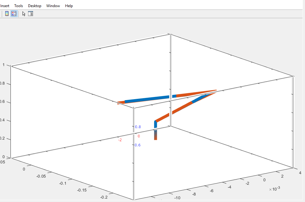
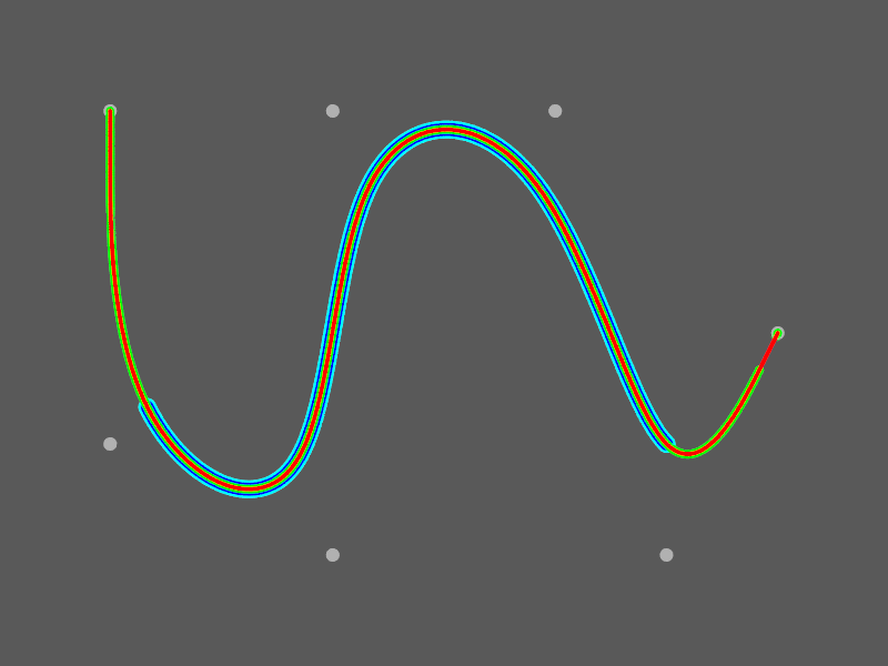
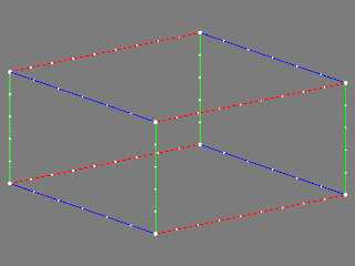
Here's an image rendered with that code.
Btw.
I reached the same conclusion as m@b:
The posted spline code does not generate a spline with the same shape as the one
that is shown in the original screenshot.
Also, it does not fit inside the "wireframe" box in the attached image.
Further, the image is cropped a bit too tight:
On one of the axes we can see that there is a 10^-3 axis multiplier, but it is
not possible to see if this also applies to the other 2 axes.
--
Tor Olav
http://subcube.com
https://github.com/t-o-k
Post a reply to this message
Attachments:
Download 'cameraplacementquestion.png' (24 KB)
Preview of image 'cameraplacementquestion.png'
|
|
| |
| |
|
|
|
|
| |
| |
|
|
"Tor Olav Kristensen" <tor### [at] TOBEREMOVEDgmailcom> wrote:
> Hehe, there you tempted me to have a look at this.
>
> I opened the screenshot in gimp and copied the 3 axes around to check if the
> camera used could be a orthographic camera. It seems so.
Ah. It didn't seem to be a purely perspective view, but it was early and I was
heading out. It certainly had that "view-camera corrected film-plane" look, if
you know what I mean.
Perhaps some of the work done with Norbert Kern's 'Position-Finder' tool could
be used to back-calculate points for the spline to get something that more
closely resembles the posted 3rd-party software graphic.
.... or the original data set could be posted. ;)
Post a reply to this message
|
|
| |
| |
|
|
|
|
| |
| |
|
|
"Bald Eagle" <cre### [at] netscapenet> wrote:
> "Tor Olav Kristensen" <tor### [at] TOBEREMOVEDgmailcom> wrote:
>
> > Hehe, there you tempted me to have a look at this.
> >
> > I opened the screenshot in gimp and copied the 3 axes around to check if the
> > camera used could be a orthographic camera. It seems so.
>
> Ah. It didn't seem to be a purely perspective view, but it was early and I was
> heading out. It certainly had that "view-camera corrected film-plane" look, if
> you know what I mean.
>
> Perhaps some of the work done with Norbert Kern's 'Position-Finder' tool could
> be used to back-calculate points for the spline to get something that more
> closely resembles the posted 3rd-party software graphic.
I've now hat a look at his macro. It seems that what it could be used for in
this case, is to calculate the coordinates of the corners of the box projected
onto a plane.
But the same could be achieved with less work by loading the image into e.g.
Gimp and then finding the coordinates of the corners within the cameras view
plane.
From these coordinates, it may be possible to solve several equations with
several unknowns to find the possible camera vectors.
> .... or the original data set could be posted. ;)
Yes.
But I'm now wondering if the original poster used another spline type in the
other tool. The spline type in the POV-Ray code is "b_spline". But I've not been
able to find out what spline type that is supposed to be. I very much doubt that
it is the B-splines described here:
https://en.wikipedia.org/wiki/B-spline
Perhaps the b stands for Bezier (?) Maybe someone can verify this...
--
Tor Olav
http://subcube.com
https://github.com/t-o-k
Post a reply to this message
|
|
| |
| |
|
|
|
|
| |
| |
|
|
On 2022-05-26 10:17 (-4), Tor Olav Kristensen wrote:
>
> But I'm now wondering if the original poster used another spline type in the
> other tool. The spline type in the POV-Ray code is "b_spline". But I've not been
> able to find out what spline type that is supposed to be. I very much doubt that
> it is the B-splines described here:
>
> https://en.wikipedia.org/wiki/B-spline
>
> Perhaps the b stands for Bezier (?) Maybe someone can verify this...
POV-Ray's b_spline is indeed a 3rd degree B-spline. I verified this a
few years ago by plotting points derived by de Boor's algorithm against
a POV-Ray b_spline. I have a very poor understanding of what is going
on mathematically, but I do know that b_spline is not a Bezier curve.
I found the Wikipedia article quite confusing, especially since all of
the illustrations have the curves intersecting the endpoints, yet de
Boor's algorithm, which the article links to, does not produce this
result. I know that Bezier curves are related to B-splines, but I
haven't figured out how.
Post a reply to this message
Attachments:
Download 'b-spline_tryout.png' (19 KB)
Preview of image 'b-spline_tryout.png'
|
|
| |
| |
|
|
|
|
| |
| |
|
|
Cousin Ricky <ric### [at] yahoocom> wrote:
> I found the Wikipedia article quite confusing, especially since all of
> the illustrations have the curves intersecting the endpoints, yet de
> Boor's algorithm, which the article links to, does not produce this
> result. I know that Bezier curves are related to B-splines, but I
> haven't figured out how.
This is very helpful, IMHO:
https://www.geeksforgeeks.org/difference-between-spline-b-spline-and-bezier-curves/
Post a reply to this message
|
|
| |
| |
|
|
|
|
| |
| |
|
|
Cousin Ricky <ric### [at] yahoocom> wrote:
> POV-Ray's b_spline is indeed a 3rd degree B-spline. I verified this a
> few years ago by plotting points derived by de Boor's algorithm against
> a POV-Ray b_spline. I have a very poor understanding of what is going
> on mathematically, but I do know that b_spline is not a Bezier curve.
It is not, necessarily, but I believe that all Bezier curves are b-splines.
> I found the Wikipedia article quite confusing, especially since all of
> the illustrations have the curves intersecting the endpoints, yet de
> Boor's algorithm, which the article links to, does not produce this
> result. I know that Bezier curves are related to B-splines, but I
> haven't figured out how.
Yeah, you have to get into the details and have them fresh in your mind to have
most of the articles that purport to "explain" the difference to make any sense.
It's more that they describe them - in the way the POV-Ray documentation
"explains" things. It's a lot clearer and makes more sense if you already know
the answers... :D
Try:
https://opensourc.es/blog/b-spline/
And also, I believe that The NURBS Book has a pretty comprehensive explanation
of what all the various splines types are that lead up to the development of
NURBS - Non Uniform Rational B-Splines.
IIRC, the key points have to due with multiplicity of knot vectors, and a lot
more localized influence of any given knot on the shape of the overall curve.
Post a reply to this message
|
|
| |
| |
|
|
|
|
| |
| |
|
|
Cousin Ricky <ric### [at] yahoocom> wrote:
> On 2022-05-26 10:17 (-4), Tor Olav Kristensen wrote:
> >
> > But I'm now wondering if the original poster used another spline type in the
> > other tool. The spline type in the POV-Ray code is "b_spline". But I've not been
> > able to find out what spline type that is supposed to be. I very much doubt that
> > it is the B-splines described here:
> >
> > https://en.wikipedia.org/wiki/B-spline
> >
> > Perhaps the b stands for Bezier (?) Maybe someone can verify this...
>
> POV-Ray's b_spline is indeed a 3rd degree B-spline. I verified this a
> few years ago by plotting points derived by de Boor's algorithm against
> a POV-Ray b_spline.
Ok. I did the same test as you. It seems to be b-splines with a closed knot
vector. Their order is 4, i.e. 3rd degree (as you found) plus 1.
> I have a very poor understanding of what is going
> on mathematically, but I do know that b_spline is not a Bezier curve.
As Bill mentioned; B-spline curves are a superset of Bezier curves.
> I found the Wikipedia article quite confusing, especially since all of
> the illustrations have the curves intersecting the endpoints, yet de
> Boor's algorithm, which the article links to, does not produce this
> result. I know that Bezier curves are related to B-splines, but I
> haven't figured out how.
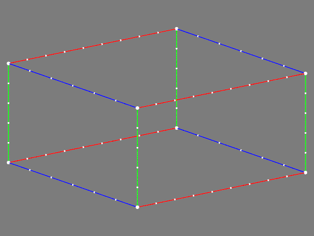
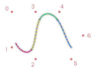
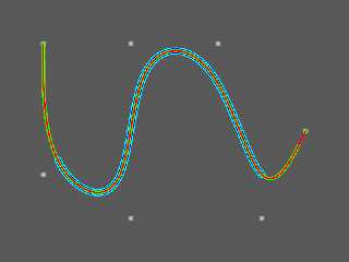
To make B-splines intersect the endpoints, you can use open knot vectors.
Alternatively you can repeat the endpoints. To see how to do this,
have a look at the source code below and the attached image.
The file NURBS_29.inc in below can be found here:
http://news.povray.org/povray.binaries.scene-files/thread/%3Cweb.4c327e199f459e99c734aecd0%40news.povray.org%3E/
// ===== 1 ======= 2 ======= 3 ======= 4 ======= 5 ======= 6 ======= 7
#version 3.7;
global_settings { assumed_gamma 1.0 }
#include "colors.inc"
#include "NURBS_29.inc"
// ===== 1 ======= 2 ======= 3 ======= 4 ======= 5 ======= 6 ======= 7
default {
texture {
pigment { color White }
finish {
diffuse 0
emission color White
}
}
}
background { color Gray10 }
camera {
orthographic
location -5*z
}
// ===== 1 ======= 2 ======= 3 ======= 4 ======= 5 ======= 6 ======= 7
#declare Size = 7;
#declare PP =
array[Size] {
<-3, +2, 0>, // 0
<-3, -1, 0>, // 1
<-1, -2, 0>, // 2
<-1, +2, 0>, // 3
<+1, +2, 0>, // 4
<+2, -2, 0>, // 5
<+3, 0, 0> // 6
}
;
#declare Radius = 0.01;
union {
ShowPoints1A3D(
PP, // Points1A3D
false, // WrapU
6*Radius // Radius
)
pigment { color Gray40 }
translate +5*z
}
// ===== 1 ======= 2 ======= 3 ======= 4 ======= 5 ======= 6 ======= 7
// Uniform B-Spline of order 4 with closed knot vector
sphere_sweep {
b_spline
Size,
#for (I, 0, Size - 1)
PP[I], 8*Radius
#end // for
tolerance 0.1
pigment { color Cyan }
translate +4*z
}
// ===== 1 ======= 2 ======= 3 ======= 4 ======= 5 ======= 6 ======= 7
#declare Order = 4;
#declare Open = false;
// ===== 1 ======= 2 ======= 3 ======= 4 ======= 5 ======= 6 ======= 7
// The circumstantial way
#macro B_Spline_Function1A(OrderU, KnotsU, Values1A)
#local SizeU = Size1A(Values1A);
#local BlendU_Fns = BlendFunctions(SizeU, OrderU, KnotsU);
function(_t) {
0
#for (I, 0, SizeU - 1)
#local C = Values1A[I];
#switch (C)
#case (-1)
-BlendU_Fns[I](_t)
#break
#case (0)
#break
#case (+1)
+BlendU_Fns[I](_t)
#break
#else
+BlendU_Fns[I](_t)*C
#end // switch
#end // for
}
#end // macro B_Spline_Function1A
#declare KK =
UniformKnotVector(
Open, // Open
Order, // Order
Size // NrOfPoints
)
;
// Closed: { -3/4,-2/4,-1/4, 0/4, 1/4, 2/4, 3/4, 4/4, 5/4, 6/4, 7/4 }
// Open: { 0/4, 0/4, 0/4, 0/4, 1/4, 2/4, 3/4, 4/4, 4/4, 4/4, 4/4 }
#declare PPx = ExtractComponent1A(PP, x);
#declare PPy = ExtractComponent1A(PP, y);
#declare PPz = ExtractComponent1A(PP, z);
#declare B_Spline_FnX =
B_Spline_Function1A(
Order, // OrderU
KK, // KnotsU
PPx // Values1A
)
;
#declare B_Spline_FnY =
B_Spline_Function1A(
Order, // OrderU
KK, // KnotsU
PPy // Values1A
)
;
#declare B_Spline_FnZ =
B_Spline_Function1A(
Order, // OrderU
KK, // KnotsU
PPz // Values1A
)
;
union {
ShowFunctions1A3D(
B_Spline_FnX, // xFn
B_Spline_FnY, // yFn
B_Spline_FnZ, // zFn
false, // WrapU
0, // MinU
1, // MaxU
200, // ResU
6*Radius // Radius
)
pigment { color Blue }
translate +3*z
}
// ===== 1 ======= 2 ======= 3 ======= 4 ======= 5 ======= 6 ======= 7
// Alternative way,
// but now with 2 repeated points in both the beginning and the end.
#declare NewSize = Size + 4;
#declare QQ =
array[NewSize] {
PP[0], // 0
PP[0], // 1
PP[0], // 2
PP[1], // 3
PP[2], // 4
PP[3], // 5
PP[4], // 6
PP[5], // 7
PP[6], // 8
PP[6], // 9
PP[6] // 10
}
;
// Uniform B-Spline
union {
Show_UBS_1A3D(
QQ, // Points1A3D
Open, // OpenU
Order, // OrderU
false, // WrapU
200, // ResU
2*Radius // Radius
)
pigment { color Red }
translate +1*z
}
// ===== 1 ======= 2 ======= 3 ======= 4 ======= 5 ======= 6 ======= 7
// Now check if also the built in B-spline sphere sweep can be
// tricked into reaching the points in the beginning and the end.
sphere_sweep {
b_spline
NewSize,
#for (I, 0, NewSize - 1)
QQ[I], 4*Radius
#end // for
tolerance 0.1
pigment { color Green }
translate +2*z
}
// ===== 1 ======= 2 ======= 3 ======= 4 ======= 5 ======= 6 ======= 7
--
Tor Olav
http://subcube.com
https://github.com/t-o-k
Post a reply to this message
Attachments:
Download 'b_spline_sphere_sweep.png' (33 KB)
Preview of image 'b_spline_sphere_sweep.png'
|
|
| |
| |
|
|
|
|
| |
| |
|
|
Thank you so much for the help, I really appreciate it. The idea is to create a
smooth curve passing through the 6 control points. The screenshot that I posted
was a 3d plot obtained using matlab.Now all I need is to shit the the first
point in the negative z direction so that upper half doesn't look larger than
the upper half.
A better version of what I am trying to do can be found in this video.
https://www.cosseratrods.org/videos/RALvideos/Case2-front_view_web.mp4
I have a small favor to ask. any advice on how to make this close to the model
in the video would be great.
Thank you once again.
"m@b" <sai### [at] googlemailcom> wrote:
> On 23/05/2022 1:08 am, Aj wrote:
> > Hello everyone,
> >
> > I created a spline object using the following code, but I could not get the
> > proper camera position. I was wondering if there is some systematic way to
> > figure out the camera position, and angle and look at vectors for a given shape.
> > Or is it just trial and error? Can someone please help me to get the proper
> > camera setup so as to obtain the figure attached:
> >
> >
>
> The points in your sphere_sweep don't plot the figure in the screen
> shot, the points form a more or less straight line in the z direction.
> (1.png) (Points 5 & 6 are the same.)
>
> Looking again at the screen shot, I notice that the 3 axes are at
> different scales. If I apply scaling and rotation to the points I can
> get something like your figure. Scale = <200,10,1> rotate<0,90,0> (2.png)
>
> Note that I have moved the camera to <0,0,-200>, looking at <0,0,0>. I
> find it easier to keep track of x,y,z if the camera is in the minus z
> position.
>
> If you want a point for the camera to look at, you can find the mean
> center of your plot thus:
>
> #declare Thing_max = max_extent(Thing);
> #declare Thing_min = min_extent(Thing);
> #declare Thing_centre = (max_extent(Thing) + min_extent(Thing))/2;
>
> (Red sphere)
>
> ---------------------------------------------------------------
> #include"colors.inc"
> camera {
> //location <-0.0872 , -1.8850 , 4.8301 >*3.5
> location <0,0,-200>
> look_at <0,0,0>
> angle 22
> }
>
>
> light_source { <100,100,-100> color rgb<1,1,1> }
>
> background {color rgb<0.5,0.5,0.5> }
>
> #declare Scale = <200,10,1>;
> //#declare Scale = <1,1,1>;
>
> #declare P01 = Scale*< 0, 0, -20>;
> #declare P02 = Scale*< 2.583e-09,-2.7093e-08, 3>;
> #declare P03 = Scale*< 0.075646, -0.91834, 8.9288>;
> #declare P04 = Scale*< 0.076898, -2.3756, 14.7492>;
> #declare P05 = Scale*<-0.15231, -4.2038, 20.4593>;
> #declare P06 = Scale*<-0.15231, -4.2038, 20.4593>;
>
> #declare Thing = union{
>
> sphere{P01 0.9 pigment{rgb<0,1,0>}}
> sphere{P02 0.9 pigment{rgb<0,1,0>}}
> sphere{P03 0.9 pigment{rgb<0,1,0>}}
> sphere{P04 0.9 pigment{rgb<0,1,0>}}
> sphere{P05 0.9 pigment{rgb<0,1,0>}}
> sphere{P06 0.5 pigment{rgb<0,1,0>}}
>
>
> sphere_sweep {
> //b_spline
> linear_spline
> 6,
> P01,0.5,
> P02,0.5,
> P03,0.5,
> P04,0.5,
> P05,0.5,
> P06,0.5
> tolerance 0.1
> texture{ pigment{ color rgb<0.69,0.99,0.15>}
> finish { phong 1
> ambient 0.3
> }
> }
> //scale<2,2,0.35> rotate<-90,0,0> translate<0,-2,3>
>
> }
>
>
>
> //rotate<0,90,0>
> rotate<-90,0,0>
> }
>
>
> #declare Thing_max = max_extent(Thing);
> #declare Thing_min = min_extent(Thing);
> #declare Thing_centre = (max_extent(Thing) + min_extent(Thing))/2;
>
> sphere{Thing_centre, 1.5 pigment{rgb<1,0,0>} rotate<0,360*clock,0>}
>
> //box{Thing_min, Thing_max pigment{rgbt<1,0,0,0.8>}
> rotate<0,360*clock,0>}
>
> object{Thing rotate<0,360*clock,0>}
Post a reply to this message
|
|
| |
| |
|
|
|
|
| |
|
|