|
|
|
|
|
|
| |
| |
|
|
|
|
| |
| |
|
|
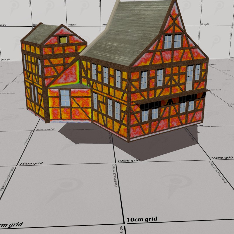
Hmmm... I am getting frustrated now. I fine tuned the geometry and the
textures and still get the same problem, concentrated as it were, in the
green field in this false colours proximity image. I don't know what is
happening. :-/
--
Thomas
Post a reply to this message
Attachments:
Download 'ep_proximity_test1.jpg' (135 KB)
Preview of image 'ep_proximity_test1.jpg'
|
|
| |
| |
|
|
|
|
| |
| |
|
|
Am 20.09.2017 um 13:35 schrieb Thomas de Groot:
> Hmmm... I am getting frustrated now. I fine tuned the geometry and the
> textures and still get the same problem, concentrated as it were, in the
> green field in this false colours proximity image. I don't know what is
> happening. :-/
If the building isn't a single solid chunk, the walls might be too thin
for the proximity algorithm to work properly.
Post a reply to this message
|
|
| |
| |
|
|
|
|
| |
| |
|
|
On 20-9-2017 14:16, clipka wrote:
> Am 20.09.2017 um 13:35 schrieb Thomas de Groot:
>> Hmmm... I am getting frustrated now. I fine tuned the geometry and the
>> textures and still get the same problem, concentrated as it were, in the
>> green field in this false colours proximity image. I don't know what is
>> happening. :-/
>
> If the building isn't a single solid chunk, the walls might be too thin
> for the proximity algorithm to work properly.
>
That is true, which is why I closed all the openings. I am presently
testing a hunch which might be the solution...
--
Thomas
Post a reply to this message
|
|
| |
| |
|
|
|
|
| |
| |
|
|
[reading]
"Elementary, my dear Watson", said Sherlock Holmes, picking up the violin.
"Come on, Holmes, you do not pretend to have solved the disappearance of
Lord Gutenbach, do you? Even for you this case might be too difficult!"
The detective smiled while tuning the violin. "But I do have solved the
case, my friend. I often told you that when you had ruled out all the
obvious reasons, the most unlikely ones would prove to hold the key to
the mystery."
"And what was the key in this case?", asked Watson with a sceptical air.
"Oh, it was obvious once I thought about it. The key, my dear Watson,
was the index finger of Lord Gutenbach's left glove".
"You have lost me now, Holmes. Please explain."
"The key was the fact that it was a /yellow/ glove."
From: The Gutenbach House Mystery; unpublished
[/reading]
==============================================================================
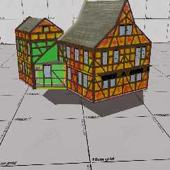
Somehow the solution was elementary and yet still puzzling for me. The
object had been rotated 180 degrees /before/ calculating the df3, and
normally this should not have made a difference... except if I had
failed to take this rotation into account, somewhere, at a later stage.
I am unable yet to see where I went wrong but taking the rotation out
solves the case as the image shows.
--
Thomas
Post a reply to this message
Attachments:
Download 'ep_proximity_test.jpg' (136 KB)
Preview of image 'ep_proximity_test.jpg'
|
|
| |
| |
|
|
|
|
| |
| |
|
|
"Norbert Kern" <nor### [at] t-online de> wrote:
> probably you overcame the texture fit problem.
> If not I can recommend proximity pattern by using an ambient occlusion render
> together with the usage of Rune's illusion code. This method is fast and very
> precise for small details.
>
That's a beautiful image.
I'm a big fan of Rune's illusion.inc code. If I understand your method
correctly, it means generating an ambient occlusion render first (in whichever
way you want to go about that--a grayscale image, with the entire scene and
object using a temporary white pigment?) Then, using illusion.inc to
'camera-project' that AO render back onto the object's real texture, as an
additional overlay.
If I'm correct about the method, then the grayscale AO render first needs to be
taken into, say, Photoshop, to create an alpha-channel mask (using the *same*
image for that but inverted, to create transparency for the white parts of the
image.) *Then* it's overlayed onto the object, so that the real texture can show
through--except where the AO render has darker areas.
Correct so far? (I hope I'm making sense.) Or does your method use an actual
'proximity pattern' as well, in some way?
To Thomas: Nice work with your trials and experiments. I still haven't played
around with the proximity pattern code yet; real-life chores keep getting in the
way. Very irritating :-/ de> wrote:
> probably you overcame the texture fit problem.
> If not I can recommend proximity pattern by using an ambient occlusion render
> together with the usage of Rune's illusion code. This method is fast and very
> precise for small details.
>
That's a beautiful image.
I'm a big fan of Rune's illusion.inc code. If I understand your method
correctly, it means generating an ambient occlusion render first (in whichever
way you want to go about that--a grayscale image, with the entire scene and
object using a temporary white pigment?) Then, using illusion.inc to
'camera-project' that AO render back onto the object's real texture, as an
additional overlay.
If I'm correct about the method, then the grayscale AO render first needs to be
taken into, say, Photoshop, to create an alpha-channel mask (using the *same*
image for that but inverted, to create transparency for the white parts of the
image.) *Then* it's overlayed onto the object, so that the real texture can show
through--except where the AO render has darker areas.
Correct so far? (I hope I'm making sense.) Or does your method use an actual
'proximity pattern' as well, in some way?
To Thomas: Nice work with your trials and experiments. I still haven't played
around with the proximity pattern code yet; real-life chores keep getting in the
way. Very irritating :-/
Post a reply to this message
|
|
| |
| |
|
|
|
|
| |
| |
|
|
On 22-9-2017 16:47, Kenneth wrote:
> "Norbert Kern" <nor### [at] t-onlinede> wrote:
>
>> probably you overcame the texture fit problem.
>> If not I can recommend proximity pattern by using an ambient occlusion render
>> together with the usage of Rune's illusion code. This method is fast and very
>> precise for small details.
>>
>
> That's a beautiful image.
>
> I'm a big fan of Rune's illusion.inc code. If I understand your method
> correctly, it means generating an ambient occlusion render first (in whichever
> way you want to go about that--a grayscale image, with the entire scene and
> object using a temporary white pigment?) Then, using illusion.inc to
> 'camera-project' that AO render back onto the object's real texture, as an
> additional overlay.
>
> If I'm correct about the method, then the grayscale AO render first needs to be
> taken into, say, Photoshop, to create an alpha-channel mask (using the *same*
> image for that but inverted, to create transparency for the white parts of the
> image.) *Then* it's overlayed onto the object, so that the real texture can show
> through--except where the AO render has darker areas.
>
> Correct so far? (I hope I'm making sense.) Or does your method use an actual
> 'proximity pattern' as well, in some way?
>
> To Thomas: Nice work with your trials and experiments. I still haven't played
> around with the proximity pattern code yet; real-life chores keep getting in the
> way. Very irritating :-/
>
>
Thanks Kenneth.
I have used AO myself in other contexts but I never used (yet)
illusion.inc; the ToDo list is getting too long. ;-)
If your description of the method is correct, the draw back would be
that you have to produce a new transparency map for every new camera
setting or transformation to the object. This is not the case with the
DF3 method.
--
Thomas
Post a reply to this message
|
|
| |
| |
|
|
|
|
| |
| |
|
|
"Kenneth" <kdw### [at] gmailcom> wrote:
>
> That's a beautiful image.
>
> I'm a big fan of Rune's illusion.inc code. If I understand your method
> correctly, it means generating an ambient occlusion render first (in whichever
> way you want to go about that--a grayscale image, with the entire scene and
> object using a temporary white pigment?) Then, using illusion.inc to
> 'camera-project' that AO render back onto the object's real texture, as an
> additional overlay.
>
> If I'm correct about the method, then the grayscale AO render first needs to be
> taken into, say, Photoshop, to create an alpha-channel mask (using the *same*
> image for that but inverted, to create transparency for the white parts of the
> image.) *Then* it's overlayed onto the object, so that the real texture can show
> through--except where the AO render has darker areas.
>
> Correct so far? (I hope I'm making sense.) Or does your method use an actual
> 'proximity pattern' as well, in some way?
>
> To Thomas: Nice work with your trials and experiments. I still haven't played
> around with the proximity pattern code yet; real-life chores keep getting in the
> way. Very irritating :-/
The AO render uses good radiosity settings, no background, a simple texture and
an emissive sphere like that:
sphere {
0, 10000
texture {
pigment {color rgb 1}
finish {emission 1.2 diffuse 0}
}
}
#declare T2 =
material {
texture {
pigment {color rgb 1}
finish {ambient 0 diffuse 0.8}
}
interior {ior 1}
}
No transparency is used.
Rune's Illusion code is used to create a pigment pattern with perfect fit for a
texture map:
//______________________________________________________________________________
// illusion
#declare illusion_image = "AO render.png" ///////////////////////
#declare illusion_scale = 10;
#declare illusion_samples = 50;
#declare illusion_location = <50,0,-201.5>; // camera location
#declare illusion_angle = 46; // camera angle
#declare illusion_look_at = <0,0,0>; // camera look at
#ifndef (illusion_location) #declare illusion_location = <0,0,0>; #end
#ifndef (illusion_right) #declare illusion_right =
image_width/image_height*x; #end
#ifndef (illusion_up) #declare illusion_up = y; #end
#ifndef (illusion_direction) #declare illusion_direction = z; #end
#ifndef (illusion_sky) #declare illusion_sky = y; #end
#ifndef (illusion_angle) #declare illusion_angle = degrees (atan2
(vlength (illusion_right)/2/vlength (illusion_direction),1))*2; #end
#ifndef (illusion_look_at) #declare illusion_look_at =
illusion_location+illusion_direction; #end
#ifndef (illusion_image) #debug "\n\n--> you must specify
'illusion_image'!\n\n" #end
#declare illusion_format = strlwr (substr (illusion_image,strlen
(illusion_image)-3,4))
#if (strcmp (illusion_format,".png") != 0 & strcmp (illusion_format,".tga") !=
0)
#debug concat (
"\n\n--> extension of illusion_image: ",
strlwr (substr (illusion_image, strlen (illusion_image)-3,4)),
"\n--> illusion_image must be a .png or .tga file!\n\n"
)
#end
// CREATE THE IMAGE MAP USED IN THE ILLUSION
// *****************************************
#ifdef (illusion_image_function)
#undef illusion_image_function
#end
#declare illusion_image_function =
function {
#if (strcmp (illusion_format,".png") = 0)
pigment {image_map {png illusion_image gamma 2.2 once} translate
-0.5}
#else
pigment {image_map {tga illusion_image gamma 2.2 once} translate
-0.5}
#end
}
// CREATE THE RAW ILLUSION ALIGNED ALONG Z AXIS
// ********************************************
#declare illusion_raw =
pigment {
average
pigment_map {
[1 function {illusion_image_function (x/z,y/z,z).red}
color_map {[0 rgb 0][1 rgb <4,0,0>]}]
[1 function {illusion_image_function (x/z,y/z,z).green}
color_map {[0 rgb 0][1 rgb <0,4,0>]}]
[1 function {illusion_image_function (x/z,y/z,z).blue}
color_map {[0 rgb 0][1 rgb <0,0,4>]}]
[1 function {illusion_image_function (x/z,y/z,z).transmit}
color_map {[0 rgb 0][1 transmit 4]}]
}
}
// ALIGNMENT CALCULATIONS
// **********************
#declare illusion_t = illusion_location;
#declare illusion_z = vnormalize (illusion_look_at-illusion_location);
#declare illusion_x = vnormalize (vcross (illusion_sky, illusion_z))*tan
(radians (illusion_angle/2))*2;
#declare illusion_y = vnormalize (vcross (illusion_z, illusion_x))*tan (radians
(illusion_angle/2))*2*vlength (illusion_up)/vlength (illusion_right);
// CREATE AND ALIGN THE ILLUSION
// *****************************
#declare illusion =
pigment {
illusion_raw
matrix <
illusion_x.x,illusion_x.y,illusion_x.z,
illusion_y.x,illusion_y.y,illusion_y.z,
illusion_z.x,illusion_z.y,illusion_z.z,
illusion_t.x,illusion_t.y,illusion_t.z
>
}
#declare f_illu = function {pigment {illusion}}
#declare T3 =
material {
texture {
pigment_pattern {
illusion_raw
matrix <
illusion_x.x,illusion_x.y,illusion_x.z,
illusion_y.x,illusion_y.y,illusion_y.z,
illusion_z.x,illusion_z.y,illusion_z.z,
illusion_t.x,illusion_t.y,illusion_t.z
>
}
texture_map {
[0.5 copper3] // copper rust
[0.8 copper2] // copper patina
[0.9 copper2]
[1 copper1] // polished copper
}
}
interior {ior 1.6}
scale 1
}
//______________________________________________________________________________
Norbert
Post a reply to this message
|
|
| |
| |
|
|
|
|
| |
| |
|
|
"Norbert Kern" <nor### [at] t-onlinede> wrote:
>
> The AO render uses good radiosity settings, no background, a simple
> texture and an emissive sphere like that:
>
> sphere {
> 0, 10000
> texture {
> pigment {color rgb 1}
> finish {emission 1.2 diffuse 0}
> }
> }
>
> #declare T2 =
> material {
> texture {
> pigment {color rgb 1}
> finish {ambient 0 diffuse 0.8}
> }
> interior {ior 1}
> }
>
Yes, that make sense for the initial AO render. Thanks. Although, I'm not sure
what the reason is for interior{ior 1}.
My own 'fake AO' method-- actually just a few experiments years ago-- was to
have a similarly white object, but I also used a white plane under it, to pick
up the AO effect where the object met the plane. And a similar white outer
sphere--but used just as a background, and without radiosity(!). To create the
AO effect, I placed hundreds of point lights in a distant hemispherical pattern.
The many overlapping shadows on the object looked *similar* to a radiosity
render. But if I were to do it again, I would use your method ;-)
> Rune's Illusion code is used to create a pigment pattern with perfect fit
> for a texture map:
>
[snip]
Wow! I need to digest your code (your math trickery is something I need to
study; it uses techniques that I'm not too familiar with-- but that I really
need to learn and apply.) In all of my own uses of illusion.inc, I've never
actually tried 'mathematically' fitting the projected image to an object. I've
always done the opposite: choosing a pre-made digital photo image, then
constructing all the scene's geometry to 'fit' the photo details, when
'projected' onto the geometry! A very tedious procedure, I admit. Your code is
very much appreciated, as an alternative method for a different kind of use.
Post a reply to this message
|
|
| |
| |
|
|
|
|
| |
| |
|
|
Thomas de Groot <tho### [at] degrootorg> wrote:
>
> If your description of the method is correct, the draw back would be
> that you have to produce a new transparency map for every new camera
> setting or transformation to the object. This is not the case with the
> DF3 method.
>
You're correct, if you intend to move the camera or object(s) around.
Illusion.inc is really for a pre-set static scene (more or less, which I'll
describe below.)
Basically, illusion.inc can be thought of a an old-style 'color slide
projector', placed *at* the POV-Ray scene's camera position. The projected image
fills the entire rendered frame--but you choose which objects in the scene to
apply the projected image onto. (Each object shows only that particular portion
of the full image 'texture'.) In other words, the *same* illusion.inc image is
'attached' to any/all of the objects. The visual effect of this is fundamentally
different from applying typical image_maps to the objects: The z-depth of the
individial objects doesn't matter-- the projected image itself will always
appear the same size on them, and undistorted, even on spherical objects (for
example.)
But here's a really interesting feature (the most important one, IMO): Although
the illusion.inc 'camera position' is supposed to match the scene's real
camera-- for the best undistorted image reproduction-- the scene camera CAN be
moved around (somewhat, within limits.) I've used this for some really cool
animations; the visual result is like a 3-D 'matte painting'.
A caveat: When trying to use illusion.inc for the first time, it can be a bit
confusing to understand, visually speaking. IMO, it has a few features that are
unnecessary and only 'get in the way.' I've re-written my own version, to remove
that stuff.
Post a reply to this message
|
|
| |
| |
|
|
|
|
| |
| |
|
|
On 23/09/2017 14:39, Kenneth wrote:
> Thomas de Groot <tho### [at] degrootorg> wrote:
>
>>
>> If your description of the method is correct, the draw back would be
>> that you have to produce a new transparency map for every new camera
>> setting or transformation to the object. This is not the case with the
>> DF3 method.
>>
>
> You're correct, if you intend to move the camera or object(s) around.
> Illusion.inc is really for a pre-set static scene (more or less, which I'll
> describe below.)
>
> Basically, illusion.inc can be thought of a an old-style 'color slide
> projector', placed *at* the POV-Ray scene's camera position. The projected image
> fills the entire rendered frame--but you choose which objects in the scene to
> apply the projected image onto. (Each object shows only that particular portion
> of the full image 'texture'.) In other words, the *same* illusion.inc image is
> 'attached' to any/all of the objects. The visual effect of this is fundamentally
> different from applying typical image_maps to the objects: The z-depth of the
> individial objects doesn't matter-- the projected image itself will always
> appear the same size on them, and undistorted, even on spherical objects (for
> example.)
>
I'm sure that you can use illusion.inc in animations. You would need to
run two animations. The first to generate the AO images the second to
use that in the final images. If you could create the alpha-channel mask
in PovRay. It might be possible to do it in a continuous three step
animation.
I too am a big fan of Rune's illusion.inc code.
> But here's a really interesting feature (the most important one, IMO): Although
> the illusion.inc 'camera position' is supposed to match the scene's real
> camera-- for the best undistorted image reproduction-- the scene camera CAN be
> moved around (somewhat, within limits.) I've used this for some really cool
> animations; the visual result is like a 3-D 'matte painting'.
>
Examples, please. :-)
Flaunt it. :-)
--
Regards
Stephen
Post a reply to this message
|
|
| |
| |
|
|
|
|
| |
|
|