|
 |
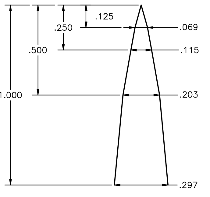
I've got a diagram of where measured points should be along a CURVE that
describes the profile of a solid edge.
You can see from the diagram, that a linear connection of the points would give
me a shape where the measured dimension points would be at the vertices of
concave angles, and so the appropriately shaped object {} would touch the lines
rather than the dimension points.
What I'd like to do is use those dimension points as the endpoints of Bezier
splines, such that the resulting curve was smooth and continuous.
I feel like, after all of the Bezier spline research that I've done, that I
really _ought_ to be able to just do this off the top of my head; however,
although I can make a continuous spline that's "smooth" and intersects the
dimension points, I don't get an "adequately" smooth curve - it has "wiggles".
This leads me to believe that either need to degree elevate the spline in order
to match the _curvature_ of the segments
OR
I need to degree reduce the cubic splines to quadratic splines so that I only
have a single intermediate control point.
I tried to quickly test that out by just making the 2 internal control points
the same, however since the control points to either side of the endpoints need
to be colinear with the control point, and preferably offset by a vector of the
same magnitude, that's a problem when the spline segments are different lengths.
So I'm leaning toward degree elevation.
But that seems like it would open things up to even MORE wiggle, and I have no
idea at the moment how to calculate the position of that extra control point.
I'm just stuck trying to figure out / remember how to calculate the positions of
the internal control points.
- BE
Post a reply to this message
Attachments:
Download '8468.png' (29 KB)
Preview of image '8468.png'
|
|