|
|
|
|
|
|
| |
| |
|
|
|
|
| |
| |
|
|
I think it has been asked here before but I can't think of the right
term. In 2d vector graphics there is a function called envelope which
allows you to take an object and distort it into any quadrangle.
I am trying the same thing in POV-Ray, but every transformation I can
pull out of my hat and the include files maintains the original
parallelogram. I tried slicing a box in half and transforming the two
sides but it ended up with an ugly crease.
Am I fooling myself into thinking this is even possible in POV-Ray?
Uncle Josh
Post a reply to this message
|
|
| |
| |
|
|
|
|
| |
| |
|
|
Josh English <Jos### [at] joshuarenglish com> wrote:
> I think it has been asked here before but I can't think of the right
> term. In 2d vector graphics there is a function called envelope which
> allows you to take an object and distort it into any quadrangle.
>
> I am trying the same thing in POV-Ray, but every transformation I can
> pull out of my hat and the include files maintains the original
> parallelogram. I tried slicing a box in half and transforming the two
> sides but it ended up with an ugly crease.
>
> Am I fooling myself into thinking this is even possible in POV-Ray?
>
> Uncle Josh
There was an object bender macro that basically took an object, turned it into a
zillion slices, and did things that way.
What you need to do is define you object as an isosurface, and then you can do
non-linear transformations on them:
http://news.povray.org/povray.binaries.images/thread/%3Cweb.5d4b7ce3a683fa3a4eec112d0%40news.povray.org%3E/
See at the top how I took a "box" and bent it.
Look through Mike Williams' Isosurface Tutorial, and you'll get an idea of what
you can do.
The control handles of the Bezier polygon in the 2D envelope tool is a neat
idea.
Would be super cool to incorporate that into a modeler....
- BE com> wrote:
> I think it has been asked here before but I can't think of the right
> term. In 2d vector graphics there is a function called envelope which
> allows you to take an object and distort it into any quadrangle.
>
> I am trying the same thing in POV-Ray, but every transformation I can
> pull out of my hat and the include files maintains the original
> parallelogram. I tried slicing a box in half and transforming the two
> sides but it ended up with an ugly crease.
>
> Am I fooling myself into thinking this is even possible in POV-Ray?
>
> Uncle Josh
There was an object bender macro that basically took an object, turned it into a
zillion slices, and did things that way.
What you need to do is define you object as an isosurface, and then you can do
non-linear transformations on them:
http://news.povray.org/povray.binaries.images/thread/%3Cweb.5d4b7ce3a683fa3a4eec112d0%40news.povray.org%3E/
See at the top how I took a "box" and bent it.
Look through Mike Williams' Isosurface Tutorial, and you'll get an idea of what
you can do.
The control handles of the Bezier polygon in the 2D envelope tool is a neat
idea.
Would be super cool to incorporate that into a modeler....
- BE
Post a reply to this message
|
|
| |
| |
|
|
|
|
| |
| |
|
|
On 7/22/2025 6:28 PM, Bald Eagle wrote:
> Josh English <Jos### [at] joshuarenglishcom> wrote:
>>
>>
>> Am I fooling myself into thinking this is even possible in POV-Ray?
>>
>
> There was an object bender macro that basically took an object, turned it into a
> zillion slices, and did things that way.
>
> What you need to do is define you object as an isosurface, and then you can do
> non-linear transformations on them:
>
>
http://news.povray.org/povray.binaries.images/thread/%3Cweb.5d4b7ce3a683fa3a4eec112d0%40news.povray.org%3E/
>
> See at the top how I took a "box" and bent it.
>
> Look through Mike Williams' Isosurface Tutorial, and you'll get an idea of what
> you can do.
>
> The control handles of the Bezier polygon in the 2D envelope tool is a neat
> idea.
> Would be super cool to incorporate that into a modeler....
>
> - BE
>
I have a bezier patch modeling system, and I could probably work it to
create a shape inside any demented cube, but I was hoping to be able to
copy meshes and deform them, not draw each one individually.
But if that's what it takes, that's what it takes!
(Isosurfaces scare me. I have no idea how you bent a box.)
- Josh
Post a reply to this message
|
|
| |
| |
|
|
|
|
| |
| |
|
|
Josh English <Jos### [at] joshuarenglishcom> wrote:
> I have a bezier patch modeling system, and I could probably work it to
> create a shape inside any demented cube, but I was hoping to be able to
> copy meshes and deform them, not draw each one individually.
>
> But if that's what it takes, that's what it takes!
Well, if you have a modeling system, then you can use the Bernstein polynomials
to access any point on the patch.
You could add a 3rd dimension with some finagling.
Then you take your mesh, find the bounding box min and max, convert all the 3D
coordinates to uv(w) coordinates, and use the Bezier splines to adjust the
coordinates of the mesh.
> (Isosurfaces scare me. I have no idea how you bent a box.)
>
> - Josh
The same way one "bends" a line to make a parabola. When your shape is an
equation, one can feed anything into it as the input.
So when I take the equation of a box and substitute x*x for x, then I get a
parabolicly bent box.
We can tilt, rotate, twist, scale, _nonlinearly scale_, perturb the surface,
etc.
- BE
Post a reply to this message
|
|
| |
| |
|
|
|
|
| |
| |
|
|
"Bald Eagle" <cre### [at] netscapenet> wrote:
> Then you take your mesh, find the bounding box min and max, convert all the 3D
> coordinates to uv(w) coordinates, and use the Bezier splines to adjust the
> coordinates of the mesh.
Take a look at:
https://discussions.unity.com/t/deforming-a-mesh-to-bezier-curve/876635
https://www.youtube.com/watch?v=S_JQUDDAsQk
https://www.rose-hulman.edu/~finn/CCLI/Notes/day21.pdf
my guess is that there are several ways that people go about this, and there are
likely libraries on GitHub and elsewhere.
MY conception of a general way to go about this would be to define a Bezier
parallelpiped consisting of 64 control points - like 4 stacked Bezier patches
having 16 control points each.
The 8 corner points would control your 3D envelope, and all of the inner control
points would control "stretching".
We could expand existing macros to create extended Bernstein polynomials in i,
j, and k.
Cycling through all of the mesh vertices and dividing the coordinates by the
AABB dimensions, you'd get the i, j, k parameters, and could plug those into the
polynomial to get the adjusted mesh vertex coordinates.
Then you could do all sorts of stuff with a mesh.
Best would be to write something in Javascript or Processing to create a
modeler, and have it write out an .inc file for the new distorted mesh.
- BW
Post a reply to this message
|
|
| |
| |
|
|
|
|
| |
| |
|
|
On 7/23/2025 9:15 AM, Bald Eagle wrote:
> "Bald Eagle" <cre### [at] netscapenet> wrote:
>
>> Then you take your mesh, find the bounding box min and max, convert all the 3D
>> coordinates to uv(w) coordinates, and use the Bezier splines to adjust the
>> coordinates of the mesh.
>
> Take a look at:
>
> https://discussions.unity.com/t/deforming-a-mesh-to-bezier-curve/876635
>
> https://www.youtube.com/watch?v=S_JQUDDAsQk
>
> https://www.rose-hulman.edu/~finn/CCLI/Notes/day21.pdf
>
> my guess is that there are several ways that people go about this, and there are
> likely libraries on GitHub and elsewhere.
>
> MY conception of a general way to go about this would be to define a Bezier
> parallelpiped consisting of 64 control points - like 4 stacked Bezier patches
> having 16 control points each.
> The 8 corner points would control your 3D envelope, and all of the inner control
> points would control "stretching".
>
> We could expand existing macros to create extended Bernstein polynomials in i,
> j, and k.
>
> Cycling through all of the mesh vertices and dividing the coordinates by the
> AABB dimensions, you'd get the i, j, k parameters, and could plug those into the
> polynomial to get the adjusted mesh vertex coordinates.
>
> Then you could do all sorts of stuff with a mesh.
>
> Best would be to write something in Javascript or Processing to create a
> modeler, and have it write out an .inc file for the new distorted mesh.
>
>
>
> - BW
>
Interesting stuff. My modeling system defines a modeling grid of points
from which I generate the necessary bicubic patches. The idea is the
points on the modeling grid are on the model, and then it calculates
everything to make the patches to connect those points. The system
requires a lot of arrays, as you can imagine, so the points are all
there ready to be used and abused.
https://joshuarenglish.com/povray/bezdoc/index.html
Once I have all the modeling grids in a group, I can probably transform
the individual points directly in the SDL. I'm not sure how the
Berenstein polynomials would help with this particular transformation. I
have to play with the application of them.
Right now I'm going through an incredibly clunky conversion in 2d:
#declare quad = array[4] {<1.95,0,-1>, <3,0,0>, <2.5,0,1.2>, <1.25, 0,
-0.25> }
// outline the quad
#for(I,0,3,1)
sphere { quad[I] 0.02 pigment { rgb 0 } }
cylinder {quad[I] quad[mod((I+1),4)] 0.02 pigment { rgb 0 } }
pigment { rgb 0.5 } }
#end
#include "math.inc"
#declare res = <10,10>;
#declare left_vector = quad[3]-quad[0];
#declare right_vector = quad[2]-quad[1];
#declare DaTexture = texture {
uv_mapping
pigment { marble }
}
mesh {
#for(V, 0, res.v-1,1)
#declare start = Interpolate(V,0,res.v,quad[0], quad[3],1);
#declare stop = Interpolate(V,0,res.v, quad[1], quad[2],1);
#declare nstart = Interpolate(V+1, 0, res.v, quad[0], quad[3], 1);
#declare nstop = Interpolate(V+1, 0, res.v, quad[1], quad[2], 1);
#for(U,0, res.u-1, 1)
#declare ll = Interpolate(U, 0, res.u, start, stop, 1);
#declare lr = Interpolate(U+1, 0, res.u, start, stop, 1);
#declare tl = Interpolate(U, 0, res.u, nstart, nstop, 1);
#declare tr = Interpolate(U+1, 0, res.u, nstart, nstop, 1);
triangle { ll, lr, tl
uv_vectors <U/res.u, V/res.v> <(U+1)/res.u, V/res.v> <U/res.u,
(V+1)/res.v>
}
triangle { lr, tl, tr
uv_vectors <(U+1)/res.u, V/res.v> <U/res.u, (V+1)/res.v>
<(U+1)/res.u, (V+1)/res.v>
}
#end // for U
#end // for V
texture { DaTexture }
}
Are you suggesting there's an easier (and maybe faster way) to do this
sort of thing? I'll have to wreck my brain on the problem.
Josh
Post a reply to this message
|
|
| |
| |
|
|
|
|
| |
| |
|
|
Josh English <Jos### [at] joshuarenglishcom> wrote:
> Are you suggesting there's an easier (and maybe faster way) to do this
> sort of thing? I'll have to wreck my brain on the problem.
Dunno if it's "easier" - that all depends upon your philosophy and code usage.
Might be faster. I would say probably.
I would strongly suggest looking over my monograph on Bezier patches and
Bernstein polynomials to get the overview, and understand what the polynomial
method actually does, and why it's a more elegant way of doing things.
https://wiki.povray.org/content/User:BillW
Then I'd dig up some of TOK's threads, his GitHub libraries, and the threads
where he teaches me all sorts of stuff about making Bezier patches the "better"
way, and I finally hammer out how to stitch a load of bicubic patches into a
torus.
Once you see what it all does, you'll understand that every point on a bicubic
patch is just an interpolation (which you already know) - but it's the sum of
the contributions of _ALL 16_ control points at that particular u,v coordinate.
So, the idea is that if you start with a unit square (or you divide your mesh
coordinates by the bounding box extents to give u,v parameters, then you can
just plug in the coordinates of a vertex and directly calculate the new position
based on any (re)arrangement of the control points.
I'm just suggesting that this be done in 3D with a full complement of additional
control points for the spatial version.
So that would be 64 points with u,v,w coordinates.
There are only 64 control points, and assembling the polynomial equation(s)
shouldn't be too difficult. I would imagine that the speed would depend mostly
on the number of triangles in your mesh.
The real challenge is visualizing what the result of moving the control points
is. Thus, my suggestion for Javascript, Processing, etc. Desmos might provide
a tedious way to do it, though possibly someone could write it for us.
- BE
Post a reply to this message
|
|
| |
| |
|
|
|
|
| |
| |
|
|
"Bald Eagle" <cre### [at] netscapenet> wrote:
> So, the idea is that if you start with a unit square (or you divide your mesh
> coordinates by the bounding box extents to give u,v parameters, then you can
> just plug in the coordinates of a vertex and directly calculate the new position
> based on any (re)arrangement of the control points.
>
> I'm just suggesting that this be done in 3D with a full complement of additional
> control points for the spatial version.
> So that would be 64 points with u,v,w coordinates.
>
> There are only 64 control points, and assembling the polynomial equation(s)
> shouldn't be too difficult. I would imagine that the speed would depend mostly
> on the number of triangles in your mesh.
I used the code from one of my monograph illustrations to form the basis for
rewriting an expanded Bernstein polynomial equation.
Set up the 64 control points.
Added an extra loop to show the extended control grid.
Seems to work when it just sits there and does nothing. ;)
Need to get a low poly mesh and start moving control points around.
- BE
Post a reply to this message
|
|
| |
| |
|
|
|
|
| |
| |
|
|
hi,
"Bald Eagle" <cre### [at] netscapenet> wrote:
> ...
> Seems to work when it just sits there and does nothing. ;)
> Need to get a low poly mesh and start moving control points around.
"there you are" ;-). (attached, 42 vectors, 80 faces)
regards, jr.
Post a reply to this message
Attachments:
Download '250724_ng.inc.txt' (3 KB)
|
|
| |
| |
|
|
|
|
| |
| |
|
|
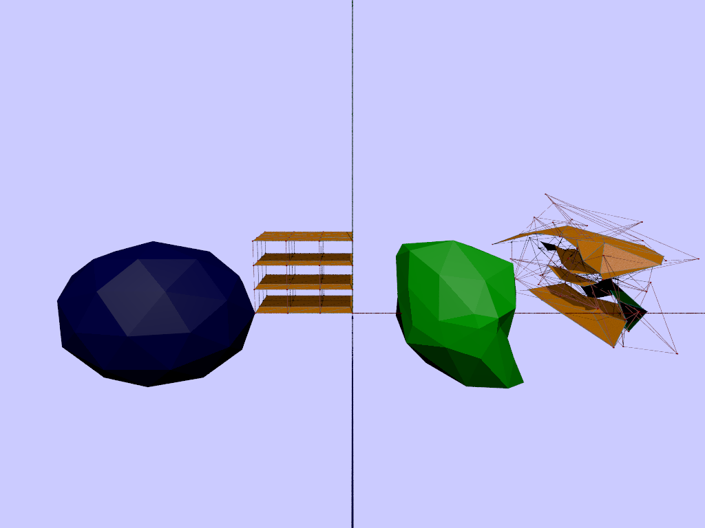
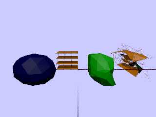
"jr" <cre### [at] gmailcom> wrote:
> "there you are" ;-). (attached, 42 vectors, 80 faces)
Rock, paper, scissors.
Bezier Parallelpiped crushes them all.
- BE
Post a reply to this message
Attachments:
Download 'bezier_3d_for_mesh.png' (109 KB)
Preview of image 'bezier_3d_for_mesh.png'
|
|
| |
| |
|
|
|
|
| |
|
|