|
|
|
|
|
|
| |
| |
|
|
|
|
| |
| |
|
|
"Trevor G Quayle" <Tin### [at] hotmail com> wrote:
> > Nice, this is really starting to come together, looking good. What's the parse
> > time for the grime algorithm per head mesh here?
>
> I am using very low testing settings so I can get quick results, but parsing
> depends on the sample resolution, and number of normals traced. On my home
> machine, with res set to 400, number of trces set to 32, this parsed in
> ~30seconds, including ~7seconds to load the mesh (~35MB). Rendering is another
> 40secs on top of that, mostly because of all the intersections for each
> grime-pixel. I've been think about a way to try to make a procedural texture
> out of it rather than the current method.
>
> -tgq
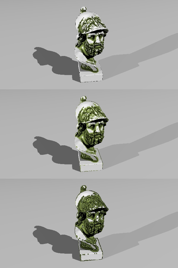
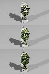
I figured out a way to convert my number to a pigment: save to an array, export
as .df3 file and read in as density_file pattern. This speeds it up
considerably on the render time. The average render time for the heads shown
with a ersoltuion setting of 400 was about 30sec compared to over 60sec
previously, with the majority (26s) being parse time. I gave me the offshoot
ability of using the interpolate function for density files. The 2nd image ins
with interpolate 1, and the 3rd is with interpolate 2. The interpolate 2 seems
to cause banding at the transition points. Interpolate 1 is ok (there are
issues at smaller resolutions though.
One thing I noticed is that with interpolate 1 there is a distinct shift down
and to the left. Is there a bias in the internal interpolate function? This is
something that I have noticed before with interpolate.
-tgq com> wrote:
> > Nice, this is really starting to come together, looking good. What's the parse
> > time for the grime algorithm per head mesh here?
>
> I am using very low testing settings so I can get quick results, but parsing
> depends on the sample resolution, and number of normals traced. On my home
> machine, with res set to 400, number of trces set to 32, this parsed in
> ~30seconds, including ~7seconds to load the mesh (~35MB). Rendering is another
> 40secs on top of that, mostly because of all the intersections for each
> grime-pixel. I've been think about a way to try to make a procedural texture
> out of it rather than the current method.
>
> -tgq
I figured out a way to convert my number to a pigment: save to an array, export
as .df3 file and read in as density_file pattern. This speeds it up
considerably on the render time. The average render time for the heads shown
with a ersoltuion setting of 400 was about 30sec compared to over 60sec
previously, with the majority (26s) being parse time. I gave me the offshoot
ability of using the interpolate function for density files. The 2nd image ins
with interpolate 1, and the 3rd is with interpolate 2. The interpolate 2 seems
to cause banding at the transition points. Interpolate 1 is ok (there are
issues at smaller resolutions though.
One thing I noticed is that with interpolate 1 there is a distinct shift down
and to the left. Is there a bias in the internal interpolate function? This is
something that I have noticed before with interpolate.
-tgq
Post a reply to this message
Attachments:
Download 'trace-4.jpg' (135 KB)
Preview of image 'trace-4.jpg'
|
|
| |
| |
|
|
|
|
| |
| |
|
|
> One thing I noticed is that with interpolate 1 there is a distinct shift down
> and to the left. Is there a bias in the internal interpolate function? This is
> something that I have noticed before with interpolate.
Yeah - it's to do with where you consider the authoritative pixel value to be -
in the center of the voxel, or in the lower corner.
I remember writing code to correct for exactly that in my DF3 proximity code. I
need to look at it again, as it might have changed during the 3.7 beta cycle
(there was a post about interpolation a few months back I recall).
Cheers,
Edouard.
Post a reply to this message
|
|
| |
| |
|
|
|
|
| |
| |
|
|
Am 17.03.2011 03:49, schrieb Trevor G Quayle:
> The interpolate 2 seems to cause banding at the transition points.
Cubic interpolation produces "overshoot" and "undershoot" at sharp
transitions. I usually store values from 0.25 to 0.75 in df3 files to
avoid such problems.
> One thing I noticed is that with interpolate 1 there is a distinct shift down
> and to the left. Is there a bias in the internal interpolate function? This is
> something that I have noticed before with interpolate.
It was known (and fixed) for interpolation of input images, but has
never been examined for df3 files yet.
Post a reply to this message
|
|
| |
| |
|
|
|
|
| |
| |
|
|
"Edouard" <pov### [at] edouardinfo> wrote:
> > One thing I noticed is that with interpolate 1 there is a distinct shift down
> > and to the left. Is there a bias in the internal interpolate function? This is
> > something that I have noticed before with interpolate.
>
> Yeah - it's to do with where you consider the authoritative pixel value to be -
> in the center of the voxel, or in the lower corner.
>
> I remember writing code to correct for exactly that in my DF3 proximity code. I
> need to look at it again, as it might have changed during the 3.7 beta cycle
> (there was a post about interpolation a few months back I recall).
>
> Cheers,
> Edouard.
I added a half pixel shift to the interpolated version and it seems correct that
way. Looks like it may need updating in 3.7 to correct this.
-tgq
Post a reply to this message
|
|
| |
| |
|
|
|
|
| |
| |
|
|
clipka <ano### [at] anonymousorg> wrote:
> Am 17.03.2011 03:49, schrieb Trevor G Quayle:
>
> > The interpolate 2 seems to cause banding at the transition points.
>
> Cubic interpolation produces "overshoot" and "undershoot" at sharp
> transitions. I usually store values from 0.25 to 0.75 in df3 files to
> avoid such problems.
I guess this is partly the wrap-around banding. I have tried a few fixes, but
none are satisfactory. Probably just best to not use interpolate 2 for my
current usage and stick with linear or perahps my own function coded
interpolation.
>
> > One thing I noticed is that with interpolate 1 there is a distinct shift down
> > and to the left. Is there a bias in the internal interpolate function? This is
> > something that I have noticed before with interpolate.
>
> It was known (and fixed) for interpolation of input images, but has
> never been examined for df3 files yet.
I ran a test with a 1/2 pixel shift which corrected it, so it does look like
this just needs to be corrected for df3 files in the code.
-tgq
Post a reply to this message
|
|
| |
| |
|
|
|
|
| |
| |
|
|
Had a look at addressing the issue I was having with shallow angles picking up
ridges. I did some testing and found that this is a result of how trace works
(on smooth meshes in particular). The intersection returned is the intersection
with the flat, unsmoothed surface of the mesh (unperturbed), whereas the surface
normal returned is based on the smoothed surface normal at the point. What
happens is that very shallow traces end up intersecting with the mesh in some
locations, particularly close to triangle edges.
I thought of several solutions to avoid this:
1) have the trace function return the perturbed intersection point, not the
triangle surface: this would have to be done in the POV source. I imagine this
is difficult if not nearly impossible, hence we still get the shadow line issue
with meshes. Not likely solution at present.
2) have the trace function return the unperturbed normal at the intersection:
again this would have to be done in the POV source and would be much simpler, if
not trivial to do compared to 1. However this would change the way trace works
and, in most situations, may not be desirable, and could break older scenes.
Not likely solution.
3) manual method of 2), have two instances of the mesh used, one smoothed, one
not. the smoothed one gets used for rendering, the unsmoothed for tracing: Not
an elegant solution as it requires creating and loading two separate instances
of the same mesh.
4) similar to 3), but have encoded in mesh objects and additional "unsmooth"
keyword that would allow for the mesh smoothing to be ignored for certain
circumstances: Again, this would require POV source coding, but may be simple
to do from a coding perspective without breaking old scenes. However, not
likely a curren t solution unless I want to get into source coding.
5) manual method of 1), this is not strictly equivalent to 1, but basically
manually set an offset value to start the traces from. Essentially the initial
trace sets the intersection point and grabs the surface normal, but the
subsequent grime traces start from a point just off the surface: Very simple
flexible solution from the user standpoint as testing can be done to find the
optimal offset to use, doesn't require internal coding of trace handling.
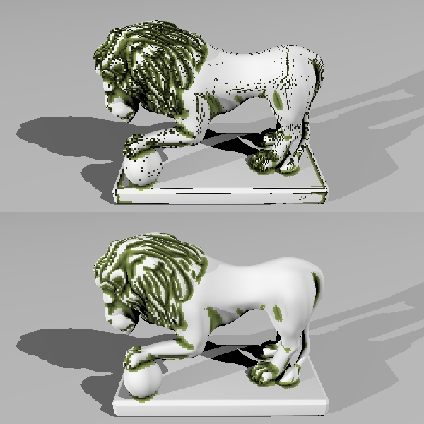
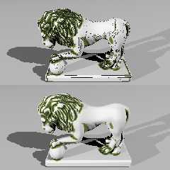
Following my simple solution #5, I added this capability into my current macro
with good results. See the attached image. For reference, the model is 200
units high, normal angle set to 85, control depth set to 20. The first image is
run with no offset. Distinct artifacts and mesh lines can be seen, particularly
the lines along the body and legs. The second image uses the same parameters
but with a offset of 0.1 with fairly favourable results.
-tgq
Post a reply to this message
Attachments:
Download 'trace2.jpg' (166 KB)
Preview of image 'trace2.jpg'
|
|
| |
| |
|
|
|
|
| |
| |
|
|
"Trevor G Quayle" <Tin### [at] hotmailcom> wrote:
> Had a look at addressing the issue I was having with shallow angles picking up
> ridges. I did some testing and found that this is a result of how trace works
> (on smooth meshes in particular). The intersection returned is the intersection
> with the flat, unsmoothed surface of the mesh (unperturbed), whereas the surface
> normal returned is based on the smoothed surface normal at the point. What
> happens is that very shallow traces end up intersecting with the mesh in some
> locations, particularly close to triangle edges.
>
> Following my simple solution #5, I added this capability into my current macro
> with good results. See the attached image. For reference, the model is 200
> units high, normal angle set to 85, control depth set to 20. The first image is
> run with no offset. Distinct artifacts and mesh lines can be seen, particularly
> the lines along the body and legs. The second image uses the same parameters
> but with a offset of 0.1 with fairly favourable results.
>
> -tgq
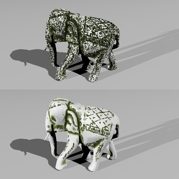
Sorry to bore you all with my testing details...
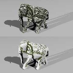
Tested this modification again with my elephant model. This is a good model as
it has very shallow details carved into it, but was showing up very dirty with
artifacts at low angles.
Model height = 200
Control depth = 20
Normal angle = 85
The first image is with no surface offset. The results are very dirty and
contaminated with lots of artifacts.
The second image uses an offset of 0.1 with very much improved results.
One thought and spin-off of this is that I have been thinking I may be able to
adapt this for outside corners/ridges for wearing.
-tgq
Post a reply to this message
Attachments:
Download 'elefunk.jpg' (165 KB)
Preview of image 'elefunk.jpg'
|
|
| |
| |
|
|
|
|
| |
| |
|
|
Am 17.03.2011 14:52, schrieb Trevor G Quayle:
>>> One thing I noticed is that with interpolate 1 there is a distinct shift down
>>> and to the left. Is there a bias in the internal interpolate function? This is
>>> something that I have noticed before with interpolate.
>>
>> It was known (and fixed) for interpolation of input images, but has
>> never been examined for df3 files yet.
>
>
> I ran a test with a 1/2 pixel shift which corrected it, so it does look like
> this just needs to be corrected for df3 files in the code.
I had a closer look by now; according to the code, there is indeed a
half-voxel shift towards negative coordinate values, for both trilinear
and tricubic interpolation.
Post a reply to this message
|
|
| |
| |
|
|
|
|
| |
| |
|
|
Am 17.03.2011 16:00, schrieb Trevor G Quayle:
> 1) have the trace function return the perturbed intersection point, not the
> triangle surface: this would have to be done in the POV source. I imagine this
> is difficult if not nearly impossible, hence we still get the shadow line issue
> with meshes. Not likely solution at present.
At present, POV-Ray does not have any code to compute such a thing as a
"pertubed intersection point".
> 2) have the trace function return the unperturbed normal at the intersection:
> again this would have to be done in the POV source and would be much simpler, if
> not trivial to do compared to 1. However this would change the way trace works
> and, in most situations, may not be desirable, and could break older scenes.
> Not likely solution.
While indeed being simpler than 1), the changes would still be
non-trivial; however, virtually all of the necessary changes should be
done anyway sooner or later to address some issues with smooth meshes,
triangles and height fields.
(Internally, POV-Ray is currently aware of two different normal vectors:
The "pertubed" normal vector after applying "normal{}" blocks, and a
"raw" normal vector as specified by geometry, /after/ "fake smoothing"
where applicable (e.g. smooth meshes). For certain computations the true
non-smoothed geometric normal would be better suited though, so in the
long run POV-Ray should be made aware of this as a third normal.)
And yes, changing the behaviour of trace() could indeed break older scenes.
> 3) manual method of 2), have two instances of the mesh used, one smoothed, one
> not. the smoothed one gets used for rendering, the unsmoothed for tracing: Not
> an elegant solution as it requires creating and loading two separate instances
> of the same mesh.
... but possible without any modifications to the POV-Ray code.
Post a reply to this message
|
|
| |
| |
|
|
|
|
| |
| |
|
|
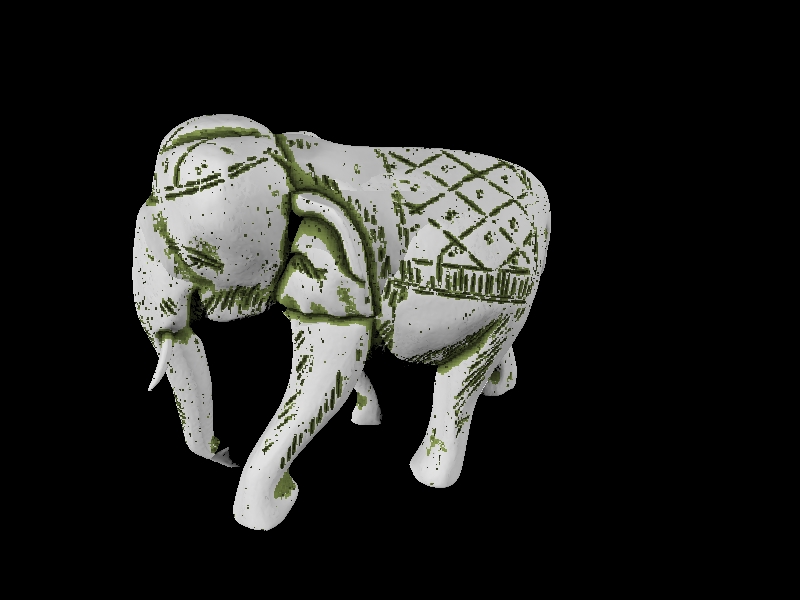
A general update on some latest experiments. I played with adding in recusive,
adaptive subsampling to help speed things up a little bit. This was only done
for the number of sample traces run around each intersection point: start with a
minimum number of traces, if intersections are found, recurse to additional
traces until the maximum depth or confidence level is reached
Three variables get set:
1) minimum recursion depth
2) maximum recursion depth
3) confidence level
Both minimum and maximum recursion depth are 2^x values so (0=1, 1=2, 2=4, etc)
usually I would always set minimum to 2 which means 4 samples are traced at
0,90,180 & 270 degrees. Confidence is based on the percent change of the
returned value from one recursion level to the next.
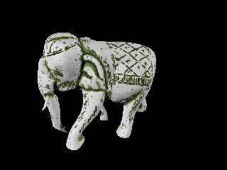
As a sample I ran my elephant model through it. The general numbers:
model height: 200 (bounding box 313 diagonal)
resolution: 500 (based on bounding box diagonal)
control depth: 15
control angle: 85
surface offset: 0.05
At this resolution, 251,001 initial traces are sent (501x501). Of these, 55,024
succeed in hitting the object (22%). This is expected because of how I am
choosing my sample grid size: given a general object size of 200 units, and a
grid of 313 units means that at best, the model fill ~41% of the grid. This is
something I may yet work on tuning.
For the testing, I used a base maximum depth of 5 (2^5 = 32 samples). At this
depth, the maximum number of traces possible is 8,032,032 on the full sample
grid (including both object intersection and normal sample traces
251,001+251,001*32), and 2,011,769 based on the successful object trace hits.
1)
min RD = 5
max RD = 5
conf = 1
total traces = 2,011,769 (100%)
parse time 112sec
2)
min RD = 2
max RD = 5
conf = 1
total traces = 1,600,309 (80%)
parse time 97sec (87%)
3)
min RD = 2
max RD = 5
conf = 0.9
total traces = 1,103,477 (55%)
parse time 76sec (68%)
4) for comparison
min RD = 2
max RD = 2
conf = 1
total traces = 471,097
parse time 48sec
Note that there is a difference between 1 & 2 despite a conficence level of 1 as
if no sample intersections are found on the first pass, the algorithm kicks out.
This is not as dramatic an impact as I was hoping for, but it does have some
value in helping with render time.
-tgq
Post a reply to this message
Attachments:
Download 'trac.jpg' (143 KB)
Preview of image 'trac.jpg'
|
|
| |
| |
|
|
|
|
| |
|
|