|
|
|
|
|
|
| |
| |
|
|
|
|
| |
| |
|
|
In article <3A91E60C.297BF165@hotmail.com>, Dan Johnson
<zap### [at] hotmail com> wrote:
> I thought that looked familiar, so I checked, and sure enough, it is an
> exact duplicate of something I made.
The basic circuit (the two transistors linked together with capacitors)
is a pretty common building block, so it's not surprising that you have
seen it before if you have done anything at all with electronics.
> Now what would be really cool is if you could take a circuit diagram,
> and have it render a circuit board with accurate resistor color
> codes, and everything. I'm sure people would pay money for that.
I'm sure people *do* pay money for software that does that...but I have
no idea how to do it. I'm having a hard enough time getting labels to
align properly. Doing something that used models of the parts would be
fairly easy, but the board traces would be next to impossible.
--
Christopher James Huff
Personal: chr### [at] maccom, http://homepage.mac.com/chrishuff/
TAG: chr### [at] tagpovrayorg, http://tag.povray.org/
<>< com> wrote:
> I thought that looked familiar, so I checked, and sure enough, it is an
> exact duplicate of something I made.
The basic circuit (the two transistors linked together with capacitors)
is a pretty common building block, so it's not surprising that you have
seen it before if you have done anything at all with electronics.
> Now what would be really cool is if you could take a circuit diagram,
> and have it render a circuit board with accurate resistor color
> codes, and everything. I'm sure people would pay money for that.
I'm sure people *do* pay money for software that does that...but I have
no idea how to do it. I'm having a hard enough time getting labels to
align properly. Doing something that used models of the parts would be
fairly easy, but the board traces would be next to impossible.
--
Christopher James Huff
Personal: chr### [at] maccom, http://homepage.mac.com/chrishuff/
TAG: chr### [at] tagpovrayorg, http://tag.povray.org/
<><
Post a reply to this message
|
|
| |
| |
|
|
|
|
| |
| |
|
|
On Tue, 20 Feb 2001 07:52:39 -0500, Chris Huff wrote:
>
>I'm sure people *do* pay money for software that does that...but I have
>no idea how to do it. I'm having a hard enough time getting labels to
>align properly. Doing something that used models of the parts would be
>fairly easy, but the board traces would be next to impossible.
Now Tony, there's a challenge if I ever saw one:-)
--
Cheers
Steve email mailto:ste### [at] zeroppsuklinuxnet
%HAV-A-NICEDAY Error not enough coffee 0 pps.
web http://www.zeropps.uklinux.net/
or http://start.at/zero-pps
6:58pm up 18 days, 20:38, 4 users, load average: 1.00, 1.01, 1.00
Post a reply to this message
|
|
| |
| |
|
|
From: Tony[B]
Subject: Re: Electrical schematics include - Multivibrator.png (1/1)
Date: 21 Feb 2001 23:12:05
Message: <3a949195@news.povray.org>
|
|
|
| |
| |
|
|
:o How did I get into this? Why is this a challenge to me?
Post a reply to this message
|
|
| |
| |
|
|
|
|
| |
| |
|
|
"Tony[B]" wrote:
> :o How did I get into this? Why is this a challenge to me?
Hey just found something that might be in interest. A finished circuit
board, and schematic made in povray.
http://ourworld.compuserve.com/homepages/Alf_Peake/PC-BOARD.JPG
--
Dan Johnson
http://www.geocities.com/zapob
Post a reply to this message
|
|
| |
| |
|
|
|
|
| |
| |
|
|
In article <3A959023.DEC3722F@hotmail.com>, Dan Johnson
<zap### [at] hotmailcom> wrote:
> Hey just found something that might be in interest. A finished circuit
> board, and schematic made in povray.
>
> http://ourworld.compuserve.com/homepages/Alf_Peake/PC-BOARD.JPG
I remember seeing that before...I think it was posted here.
Hmm, what is it? (Mr. Peake, you reading this?)
The bridge rectifier, large capacitors, and 7808 voltage regulator make
a regulated 8V power supply that takes an AC input, and there seems to
be an option to use a battery as a power source as well, but I don't
recognize the 8-pin DIP IC. That and the other components don't look
like they belong on a power-supply board. There is something labelled
"door"...maybe a trigger for a garage door opener, or an alarm for when
a door gets opened, or a doorbell. The last two make the most sense...
I think he used image_maps for the part numbers and art, and maybe a
height_field for the copper traces (it looks slightly raised)...that
kind of stuff would be a lot easier now, you could use the object
pattern and create a set of macros that makes a generic IC, capacitor,
transistor, etc. and puts the specified text/other art on it, instead of
redoing much of it for each new part. And the schematic looks like it
was hand drawn, then scanned in as 1-bit color.
BTW, I have thought about it some more, and I think it would be possible
to do a simple kind of PC board layout with my macros...it would be
limited to a single-sided board, you would have to manually place
jumpers where the traces need to cross, and the layout of the components
would follow the layout of the schematic, which is rarely the best way
to do things and means you may have to adjust things to make sure
components don't intrude on each other's space, but it should work. I'll
save it for version 2, though...
--
Christopher James Huff
Personal: chr### [at] maccom, http://homepage.mac.com/chrishuff/
TAG: chr### [at] tagpovrayorg, http://tag.povray.org/
<><
Post a reply to this message
|
|
| |
| |
|
|
From: Mark Wagner
Subject: Re: Electrical schematics include - Multivibrator.png (1/1)
Date: 23 Feb 2001 02:04:35
Message: <3a960b83@news.povray.org>
|
|
|
| |
| |
|
|
Chris Huff wrote in message ...
>...but I don't
>recognize the 8-pin DIP IC. That and the other components don't look
>like they belong on a power-supply board. There is something labelled
>"door"...maybe a trigger for a garage door opener, or an alarm for when
>a door gets opened, or a doorbell. The last two make the most sense...
It appears to be a doorbell. According to the Chip Directory, the 2811 IC
is:
2811 HT-2811 sound Door Bell, Ding Dong Holtek*
(The Chip Directory is at
http://www.xs4all.nl/~ganswijk/chipdir/index.html).
--
Mark
Post a reply to this message
|
|
| |
| |
|
|
|
|
| |
| |
|
|
In article <3a960b83@news.povray.org>, "Mark Wagner"
<mar### [at] gtenet> wrote:
> It appears to be a doorbell. According to the Chip Directory, the 2811 IC
> is:
> 2811 HT-2811 sound Door Bell, Ding Dong Holtek*
> (The Chip Directory is at
> http://www.xs4all.nl/~ganswijk/chipdir/index.html).
I identified the chip later, with a Google search. ;-)
I find the Chip Directory is often frusterating for identifying strange
chips, though it is sometimes helpful. Some of the chips I find are just
very...obscure.
(are we off-topic yet?)
--
Christopher James Huff
Personal: chr### [at] maccom, http://homepage.mac.com/chrishuff/
TAG: chr### [at] tagpovrayorg, http://tag.povray.org/
<><
Post a reply to this message
|
|
| |
| |
|
|
From: Alf Peake
Subject: Re: Electrical schematics include - Multivibrator.png (1/1)
Date: 24 Feb 2001 18:34:18
Message: <3a9844fa@news.povray.org>
|
|
|
| |
| |
|
|
"Chris Huff" <chr### [at] maccom> wrote in message
news:chrishuff-4168E1.18192122022001@news.povray.org...
> In article <3A959023.DEC3722F@hotmail.com>, Dan Johnson
> <zap### [at] hotmailcom> wrote:
>
> > Hey just found something that might be in interest. A finished
circuit
> > board, and schematic made in povray.
> >
> > http://ourworld.compuserve.com/homepages/Alf_Peake/PC-BOARD.JPG
>
> I remember seeing that before...I think it was posted here.
> Hmm, what is it? (Mr. Peake, you reading this?)
Yes Mr. Huff :-), I think I posted it on Compuserve a few years ago
but not here.
[snip]
> "door"...maybe a trigger for a garage door opener, or an alarm for
when
> a door gets opened, or a doorbell. The last two make the most
sense...
Bingo! We have a winner. A door bell kit from Maplin many years ago to
replace one that got zapped by lightning.
>
> I think he used image_maps for the part numbers and art, and maybe a
> height_field for the copper traces (it looks slightly raised)...that
Part numbers done with PSPro. The Cu track was scanned with a hand
scanner (hi-tech then), then used as a HF. Needed to accentuate the Cu
height for non-techies ;-)
[snip]
> redoing much of it for each new part. And the schematic looks like
it
> was hand drawn, then scanned in as 1-bit color.
A Logitech 4-bit BW hand scanner on the supplied schematic. Took 3
scan strips if I remember, then was image_mapped onto a bozo HF. 1-bit
coz 4-bits was way to large a file then.
[snip]
>
> --
> Christopher James Huff
--
Alf
http://www.peake42.freeserve.co.uk/
http://ourworld.compuserve.com/homepages/Alf_Peake/
gw3### [at] thersgbnet
Post a reply to this message
|
|
| |
| |
|
|
From: Alf Peake
Subject: Re: Electrical schematics include - Multivibrator.png (1/1)
Date: 24 Feb 2001 18:34:20
Message: <3a9844fc@news.povray.org>
|
|
|
| |
| |
|
|
"Mark Wagner" <mar### [at] gtenet> wrote in message
news:3a960b83@news.povray.org...
> Chris Huff wrote in message ...
> >...but I don't
> >recognize the 8-pin DIP IC. That and the other components don't
look
> >like they belong on a power-supply board. There is something
labelled
> >"door"...maybe a trigger for a garage door opener, or an alarm for
when
> >a door gets opened, or a doorbell. The last two make the most
sense...
>
>
> It appears to be a doorbell. According to the Chip Directory, the
2811 IC
> is:
>
> 2811 HT-2811 sound Door Bell, Ding Dong Holtek*
>
That's right, and the onboard rectifier allows for battery or "bell
txformer" operation.
--
Alf
http://www.peake42.freeserve.co.uk/
http://ourworld.compuserve.com/homepages/Alf_Peake/
gw3### [at] thersgbnet
Post a reply to this message
|
|
| |
| |
|
|
|
|
| |
| |
|
|
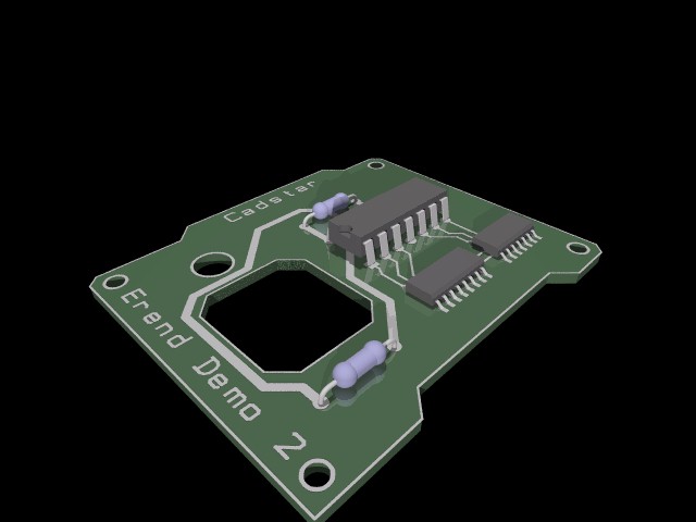
Chris Huff wrote:
> Doing something that used models of the parts would be
> fairly easy, but the board traces would be next to impossible.
With the right tools nothing is impossible :)
--
Ken Tyler
Post a reply to this message
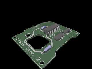
Attachments:
Download 'demo2.jpg' (31 KB)
Preview of image 'demo2.jpg'
|
|
| |
| |
|
|
|
|
| |