|
|
|
|
|
|
| |
| |
|
|
|
|
| |
| |
|
|
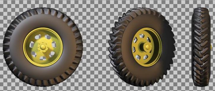
A sample from the current work, which is a megapov macro to make tyres
(1st pic) with isosurfaces given the shape of the "sculptures" (en ?) as
a png bitmap (2nd pic).
Now I have a problem. The lateral parts of the tyres are made with
lathes, and I would like to connect them smoothly to the deepest part of
my isosurface, which is a 4th degree profile. I know the tangent to my
profile, and need to keep the same on the lathe. So my question is: what
is the slope of a cubic_spline lathe profile at one of its control
points?
TIA.
--
__ __ __ __ _
| | / \ / / |_ / |/
\/\/ \__/ /_ /_ |__ \_ |\
Post a reply to this message
Attachments:
Download 'tyre4.jpg' (45 KB)
Download 'tyre4.png' (16 KB)
Preview of image 'tyre4.jpg'
Preview of image 'tyre4.png'
|
|
| |
| |
|
|
|
|
| |
| |
|
|
On Sun, 18 Jun 2000 21:04:42 +0000, Francois Dispot
<woz### [at] club-internet fr> wrote:
>A sample from the current work, which is a megapov macro to make tyres
>(1st pic) with isosurfaces given the shape of the "sculptures" (en ?) as
>a png bitmap (2nd pic).
Ah, so you've actually made it! Look great and quite like a real
thing.
>Now I have a problem. The lateral parts of the tyres are made with
>lathes, and I would like to connect them smoothly to the deepest part of
>my isosurface, which is a 4th degree profile. I know the tangent to my
>profile, and need to keep the same on the lathe. So my question is: what
>is the slope of a cubic_spline lathe profile at one of its control
>points?
Just out of curiosity, isn't the formula in the source code of POV? If
you can't find it, can you use trace() ? Lastly, why don't you use a
bezier spline lathe? At least you won't be wondering where its
tangents are pointing.
Peter Popov ICQ : 15002700
Personal e-mail : pet### [at] usanet
TAG e-mail : pet### [at] tagpovrayorg fr> wrote:
>A sample from the current work, which is a megapov macro to make tyres
>(1st pic) with isosurfaces given the shape of the "sculptures" (en ?) as
>a png bitmap (2nd pic).
Ah, so you've actually made it! Look great and quite like a real
thing.
>Now I have a problem. The lateral parts of the tyres are made with
>lathes, and I would like to connect them smoothly to the deepest part of
>my isosurface, which is a 4th degree profile. I know the tangent to my
>profile, and need to keep the same on the lathe. So my question is: what
>is the slope of a cubic_spline lathe profile at one of its control
>points?
Just out of curiosity, isn't the formula in the source code of POV? If
you can't find it, can you use trace() ? Lastly, why don't you use a
bezier spline lathe? At least you won't be wondering where its
tangents are pointing.
Peter Popov ICQ : 15002700
Personal e-mail : pet### [at] usanet
TAG e-mail : pet### [at] tagpovrayorg
Post a reply to this message
|
|
| |
| |
|
|
|
|
| |
| |
|
|
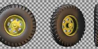
Looks good, esp. the wheels outer part and the rim. You seem to be
quite a perfectionist about the rim-tyre connection. More important,
the connection between the spline and the outer part seems a bit broken
(probably because the first/last line of the png have no constant
color). I'm not totally sure about this :-)
BTW, most tyres have some structure in form of radial/circular margins
from the vulcanization process, very small, but maybe some normal would
do that.
I would really like to see the code :-)
Christoph
--
Christoph Hormann <chr### [at] gmxde>
Homepage: http://www.schunter.etc.tu-bs.de/~chris/
Post a reply to this message
|
|
| |
| |
|
|
|
|
| |
| |
|
|
Wow...impressive! I can't wait for this to be finished...
Francois Dispot wrote:
>
> A sample from the current work, which is a megapov macro to make tyres
> (1st pic) with isosurfaces given the shape of the "sculptures" (en ?) as
> a png bitmap (2nd pic).
>
> Now I have a problem. The lateral parts of the tyres are made with
> lathes, and I would like to connect them smoothly to the deepest part of
> my isosurface, which is a 4th degree profile. I know the tangent to my
> profile, and need to keep the same on the lathe. So my question is: what
> is the slope of a cubic_spline lathe profile at one of its control
> points?
>
> TIA.
> --
> __ __ __ __ _
> | | / \ / / |_ / |/
> \/\/ \__/ /_ /_ |__ \_ |\
>
> ------------------------------------------------------------------------
> [Image] [Image]
Post a reply to this message
|
|
| |
| |
|
|
|
|
| |
| |
|
|
Peter Popov wrote:
> Just out of curiosity, isn't the formula in the source code of POV? If
> you can't find it, can you use trace() ? Lastly, why don't you use a
> bezier spline lathe? At least you won't be wondering where its
> tangents are pointing.
Excellent suggestion. The most obvious way to do what I want is a Bezier
spline... if only I happenned to find the syntax somewhere in the docs!
--
__ __ __ __ _
| | / \ / / |_ / |/
\/\/ \__/ /_ /_ |__ \_ |\
Post a reply to this message
|
|
| |
| |
|
|
|
|
| |
| |
|
|
Christoph Hormann wrote:
>
> Looks good, esp. the wheels outer part and the rim. You seem to be
> quite a perfectionist about the rim-tyre connection. More important,
> the connection between the spline and the outer part seems a bit broken
> (probably because the first/last line of the png have no constant
> color). I'm not totally sure about this :-)
I noticed this too. And you have given the right reason. Nothing to
worry about in the code.
> BTW, most tyres have some structure in form of radial/circular margins
> from the vulcanization process, very small, but maybe some normal would
> do that.
Sounds interesgting. Could you elaborate on this, please?
> I would really like to see the code :-)
Probably in a few days or so.
--
__ __ __ __ _
| | / \ / / |_ / |/
\/\/ \__/ /_ /_ |__ \_ |\
Post a reply to this message
|
|
| |
| |
|
|
|
|
| |
| |
|
|
Francois Dispot wrote:
>
[...]
>
> > BTW, most tyres have some structure in form of radial/circular margins
> > from the vulcanization process, very small, but maybe some normal would
> > do that.
>
> Sounds interesgting. Could you elaborate on this, please?
>
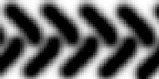
I made a quick image, maybe usable as bump_map, but probably a larger
one would be better. Many tyres also have some text including firm name
and tyre size. Maybe you should also have a direct look at some real
car's / truck's / tractor's wheels.
Christoph
--
Christoph Hormann <chr### [at] gmxde>
Homepage: http://www.schunter.etc.tu-bs.de/~chris/
Post a reply to this message
Attachments:
Download 'tyre1.png' (2 KB)
Preview of image 'tyre1.png'
|
|
| |
| |
|
|
|
|
| |
| |
|
|
On Mon, 19 Jun 2000 18:03:11 +0000, Francois Dispot <woz### [at] club-internetfr>
wrote:
>Peter Popov wrote:
>
>> Just out of curiosity, isn't the formula in the source code of POV? If
>> you can't find it, can you use trace() ? Lastly, why don't you use a
>> bezier spline lathe? At least you won't be wondering where its
>> tangents are pointing.
>
>Excellent suggestion. The most obvious way to do what I want is a Bezier
>spline... if only I happenned to find the syntax somewhere in the docs!
The information is there under Lathe, but it is very sparse.
Bezier splines are actually very easy to use. For each span (pair of points)
you have to give;
<point1>,< control point1>, <controlpoint2>,<point2>
where the control points are the end points of the tangent vectors. The curve
will be tangent to the vector at its associated point, and the length of the
vector determines the curvature at its associated point.
e.g. this makes a pretty good sphere;
lathe {
bezier_spline
12,
<0,1>, <4/3*(sqrt(2)-1), 1>, <1,4/3*(sqrt(2)-1)>, <1,0>, // 1st span
<1, 0>, <1,-4/3*(sqrt(2)-1)>, <4/3*(sqrt(2)-1), -1>, <0,-1>, // 2nd span
<0,-1>,<0,0>,<0,0>,<0,1> // 3rd span
pigment {Red}
}
(the 4/3*sqrt(2)-1 term just gives a length of vector that makes the bezier
cubic approximate to a circular arc)
David
dav### [at] hamiltonitecom
http://www.hamiltonite.com/
Post a reply to this message
|
|
| |
| |
|
|
|
|
| |
|
|