|
|
|
|
|
|
| |
| |
|
|
|
|
| |
| |
|
|
On 11/19/2016 9:26 PM, clipka wrote:
> Am 20.11.2016 um 03:04 schrieb Mike Horvath:
>> On 11/19/2016 8:48 PM, clipka wrote:
>>> Am 20.11.2016 um 02:33 schrieb Mike Horvath:
>>>> On 11/18/2016 2:22 AM, Mike Horvath wrote:
>>>>> I would like to create a three-dimensional representation of the
>>>>> L*C*h(uv) color space in the form of a cylinder.
>>>>>
>>>>> How would I do that?
>>>>>
>>>>> I may limit myself to colors that also exist in the sRGB color space.
>>>>>
>>>>> Mike
>>>>
>>>> I guess my only option is to use individually painted voxels, as I don't
>>>> see how you can enter conditional statements into a function
>>>> declaration.
>>>
>>> Did you try the `select` function?
>>>
>>
>> No I didn't!
>>
>> Can I create and store local variables too?
>
> Nope; the virtual machine currently used by POV-Ray to execute
> user-defined functions was designed solely for genuine functions; it
> doesn't do anything remotely resembling programming.
>

Do you think I could make the shape using lots of little functions?

Mike
Post a reply to this message
|
|
| |
| |
|
|
|
|
| |
| |
|
|
Am 20.11.2016 um 06:51 schrieb Mike Horvath:

> Which other converter did you use, BTW? I need to do the same for
> LAB>XYZ and XYZ>RGB as well.

Actually it was a colour picker that auto-converted upon changing the
colour model:

http://davidjohnstone.net/pages/lch-lab-colour-gradient-picker


For the most common conversion needs I found this one earlier:

http://davengrace.com/dave/cspace/
Post a reply to this message
|
|
| |
| |
|
|
|
|
| |
| |
|
|
So, I created a bunch of functions. Now how do I turn them into pigments?

(See p.t.s-f)

Mike
Post a reply to this message
|
|
| |
| |
|
|
|
|
| |
| |
|
|
On 11/21/2016 12:31 PM, Mike Horvath wrote:
> So, I created a bunch of functions. Now how do I turn them into pigments?
>
> (See p.t.s-f)
>
> Mike

Disregard. I already know how to create an approixmation of the pigment.
Sorry.


Mike
Post a reply to this message
|
|
| |
| |
|
|
|
|
| |
| |
|
|
On 11/19/2016 3:25 PM, Le_Forgeron wrote:
> Le 19/11/2016 à 19:19, Mike Horvath a écrit :
>> On 11/19/2016 12:59 PM, Le_Forgeron wrote:
>>> Le 19/11/2016 à 18:47, Mike Horvath a écrit :
>>>>
>>>> I think it would be pretty easy to produce a macro that does all of the
>>>> above. But how do I turn that into a POV-Ray function? The function
>>>> needs to work as a color as well as an isosurface I think.
>>>
>>>
>>> Basic of povray: the shape is not bound to the texture (excepted for
>>> uv_mapping).
>>>
>>> Make the work for the shape, and separately the work to map 3D
>>> coordinates to colour.
>>>
>>
>> Okay. But how?
>
> Within the attached include file, you could replace uv_vertex with your
> computed position.
>
> The top macro is UVMeshable, first parameter is an object, just
> ignore/remove it
> The two others are the resolutions... you can simplify too for your
> usage (getting ride of uv_min & uv_max).
>
> mesh{
> UVMeshable...
>
> then you insert the uv_mapped texture (and I already provided some code
> for that part in this thread)
>
> et voila.
>

I don't understand how to use these macros. Do you have examples I can
look at?

Mike
Post a reply to this message
|
|
| |
| |
|
|
|
|
| |
| |
|
|
On 11/18/2016 8:37 AM, Christian Froeschlin wrote:
> 1. Define three separate float functions yielding R, G, B separately
>
> f_R(x,y,z)
> f_B(x,y,z)
> f_G(x,y,z)
>
> 2. Create red / green / blue pigments from that using function
> pattern and red / green / blue color_maps
>
> 3. Join the 3 pigments into RGB pigment via "average" pattern.

With these three functions, do I fade them from a pure color to black,
or a pure color to transparent?

Mike
Post a reply to this message
|
|
| |
| |
|
|
|
|
| |
| |
|
|
On 11/18/2016 8:37 AM, Christian Froeschlin wrote:
> Still it would probably be useful to implement the coordinate
> transformation (including appropriate scaling of intervals) in
> a separate set of functions f_L, f_u, f_v since you need them
> multiple times in the definition of f_R, f_G, f_B.
>

Are you suggesting I use a parametric instead of an isosurface?

Mike
Post a reply to this message
|
|
| |
| |
|
|
|
|
| |
| |
|
|
On 11/23/2016 4:05 AM, Mike Horvath wrote:
> On 11/18/2016 8:37 AM, Christian Froeschlin wrote:
>> Still it would probably be useful to implement the coordinate
>> transformation (including appropriate scaling of intervals) in
>> a separate set of functions f_L, f_u, f_v since you need them
>> multiple times in the definition of f_R, f_G, f_B.
>>
>
> Are you suggesting I use a parametric instead of an isosurface?
>
> Mike

I think I would need a third parameter in addition to u and v to make it
work.


Mike
Post a reply to this message
|
|
| |
| |
|
|
|
|
| |
| |
|
|
On 11/23/2016 8:51 PM, clipka wrote:
 > Am 24.11.2016 um 01:27 schrieb Mike Horvath:
 >> On 11/23/2016 7:22 PM, Christian Froeschlin wrote:
 >>> No threshold will give the desired result using the color
 >>> conversion function directly, as clipka explained you need
 >>> a define a "distance" function for this purpose.
 >>>
 >>> Alternatively you could try to render the clipped function
 >>> (set to 0 outside the gamut) as strongly scattering media but
 >>> it may be fiddly and you don't get the look of a "surface"
 >>> regarding finish and lighting etc.
 >>>
 >>
 >> What is a "distance" function?
 >>
 >> The "convertLCH2RGBb2(y*100,sqrt(x*x+z*z)*100,atan2d(x,z))" bit is what
 >> clipka showed me.
 >
 > You may need to deconstruct the problem into easy-to-handle building
 > blocks, and tackle each of them separately.
 >
 > One building block you need is a function that maps a single RGB colour
 > component to a distance-ish scalar telling you how "far away" the colour
 > component is from the valid range (this time, just for giggles, I'm
 > contructing the function in such a way that <0 is inside, >0 is outside):
 >
 >     #declare fD = function(C) { abs(C-0.5)-0.5 }
 >
 > Another building block you need is a function that combines three such
 > distance-ish scalars, such that you get a positive value if one or more
 > parameters is positive, or a negative value if all are negative, in a
 > manner that avoid steps:
 >
 >     #declare fDist = function(Dr,Dg,Db) { max(Dr,Dg,Db) }
 >
 >
 > That's kind of all you need to know about the "distance" functions;
 > however, those functions alone don't get you anywhere.
 >
 >
 > Another necessary building block is a set of functions that map Lch
to RGB:
 >
 >     #declare fR = function(L,c,h) { ... }
 >     #declare fG = function(L,c,h) { ... }
 >     #declare fB = function(L,c,h) { ... }
 >
 > And the final building block is a set of functions that map 3D cartesian
 > space to Lch:
 >
 >     #declare fL = function(x,y,z) { y*100 }
 >     #declare fc = function(x,y,z) { sqrt(x*x+z*z)*100 }
 >     #declare fh = function(x,y,z) { atan2d(x,z) }
 >
 >
 > Once you have all these building blocks, all that's left is to plug them
 > all together.
 >
 > The final result to be compared to the threshold by the isosurface is
 > the result of the `fDist` function, so that's where you start:
 >
 >     isosurface {
 >       threshold 0
 >       function { fDist (Dr,Dg,Db) }
 >     }
 >
 > The isosurface doesn't know what `Dr`, `Dg` and `Db` are, but we know
 > they are supposed to be results of the `fD` function, using the three
 > colour channels as input:
 >
 >     isosurface {
 >       threshold 0
 >       function { fDist (
 >         fD (R),
 >         fD (G),
 >         fD (B)
 >       ) }
 >     }
 >
 > Again the isosurface doesn't know `R`, `G` and `B`:
 >
 >     isosurface {
 >       threshold 0
 >       function { fDist (
 >         fD ( fR (L,c,h) ),
 >         fD ( fG (L,c,h) ),
 >         fD ( fB (L,c,h) )
 >       ) }
 >     }
 >
 > Still not done yet, as the isosurface doesn't know `L`, `c` and `h`
either:
 >
 >     isosurface {
 >       threshold 0
 >       function { fDist (
 >         fD ( fR (fL(x,y,z),fc(x,y,z),fh(x,y,z)) ),
 >         fD ( fG (fL(x,y,z),fc(x,y,z),fh(x,y,z)) ),
 >         fD ( fB (fL(x,y,z),fc(x,y,z),fh(x,y,z)) )
 >       ) }
 >     }
 >
 > Now we have only `x`, `y` and `z` left as parameters, which is what the
 > isosurface can handle.
 >
 >
 > For bonus points, you could eliminate the multiple invocation of
 > `fL(x,y,z)`, `fc(x,y,z)` and `fh(x,y,z)`. To this end, you need to
 > provide a function that does not compute these values itself, but rather
 > takes them as parameters:
 >
 >     #declare fFinal = function(L,c,h) { fDist (
 >       fD ( fR (L,c,h) ),
 >       fD ( fG (L,c,h) ),
 >       fD ( fB (L,c,h) )
 >     ) }
 >
 >     isosurface {
 >       threshold 0
 >       function { fFinal (fL(x,y,z),fc(x,y,z),fh(x,y,z)) }
 >     }
 >
 >
 > And of course you'll want to use different names; I chose the above for
 > brevity.
 >

Next issue: What is the best way to create an accurate pigment to paint
the isosurface?

I was thinking of repurposing the following:

//------------------------------
// HSL Cylinder

#declare CSolid_HSLCylinder_Hue = pigment
{
	function {-f_th(x,y,z)/pi/2}
	color_map
	{
		// need to replace these with calls to CHSL2RGB() or CH2RGB(), then
increase the number of steps
		[0/6 srgb <1,0,0,>]
		[1/6 srgb <1,1,0,>]
		[2/6 srgb <0,1,0,>]
		[3/6 srgb <0,1,1,>]
		[4/6 srgb <0,0,1,>]
		[5/6 srgb <1,0,1,>]
		[6/6 srgb <1,0,0,>]
	}
}
#declare CSolid_HSLCylinder_Saturation = pigment
{
	cylindrical
	pigment_map
	{
		[0 CSolid_HSLCylinder_Hue]
		[1 color srgb 1/2]
	}
	scale	(1 + CSolid_Offset)
}
#declare CSolid_HSLCylinder_Lightness = pigment
{
	gradient y
	pigment_map
	{
		[0/2 color srgb 0]
		[1/2 CSolid_HSLCylinder_Saturation]
		[2/2 color srgb 1]
	}
	scale		(1 + CSolid_Offset)
	translate	-y * CSolid_Offset/2
}
#declare CSolid_HSLCylinder_Pigment = pigment {CSolid_HSLCylinder_Lightness}

Except, in this case using LCH conversion formula to create the gradients:

	[0/6 srgb <convertLCH2RGBb1(50, 50, 0),convertLCH2RGBb2(50, 50,
0),convertLCH2RGBb3(50, 50, 0)>]
	[1/6 srgb <convertLCH2RGBb1(50, 50, 60),convertLCH2RGBb2(50, 50,
60),convertLCH2RGBb3(50, 50, 60)>]
	[2/6 srgb <convertLCH2RGBb1(50, 50, 120),convertLCH2RGBb2(50, 50,
120),convertLCH2RGBb3(50, 50, 120)>]
	[3/6 srgb <convertLCH2RGBb1(50, 50, 180),convertLCH2RGBb2(50, 50,
180),convertLCH2RGBb3(50, 50, 180)>]
	[4/6 srgb <convertLCH2RGBb1(50, 50, 240),convertLCH2RGBb2(50, 50,
240),convertLCH2RGBb3(50, 50, 240)>]
	[5/6 srgb <convertLCH2RGBb1(50, 50, 300),convertLCH2RGBb2(50, 50,
300),convertLCH2RGBb3(50, 50, 300)>]
	[6/6 srgb <convertLCH2RGBb1(50, 50, 360),convertLCH2RGBb2(50, 50,
360),convertLCH2RGBb3(50, 50, 360)>]


Is this maybe a bad idea?

Mike
Post a reply to this message
|
|
| |
| |
|
|
|
|
| |
| |
|
|
Am 24.11.2016 um 20:10 schrieb Mike Horvath:

> Next issue: What is the best way to create an accurate pigment to paint
> the isosurface?

The main problem to solve is that POV-Ray's mechanisms to generate
gradient-ish pigments only supports 1-dimensional gradients.

A common solution is to construct three 1-dimensional gradient-ish
pigments -- one for each colour component -- and then mix them together
using the `average` pseudo-pattern:

    #declare FinalPigment = pigment {
      average
      pigment_map {
        [ 1.0 RedPigment   ]
        [ 1.0 GreenPigment ]
        [ 1.0 BluePigment  ]
      }
    }

Each of the `RedPigment`, `GreenPigment` and `BluePigment` component
patterns is designed in such a way that it only has the corresponding
component set to non-zero.

An important thing to note here is that the `average` pseudo-pattern
does not add colours, but averages them; so in order to achieve the full
range of colours, the component patterns must have colour ranges from 0
to 3 for the corresponding channel:

    #declare RedPigment = pigment {
      function { fR(fL(x,y,z),fc(x,y,z),fh(x,y,z), }
      colour_map {
        [ 0.0 colour rgb <0,0,0> ]
        [ 1.0 colour rgb <3,0,0> ]
      }
    }

Note that there is no need for clipping the function result: This is
automatically achieved by the colour_map.
Post a reply to this message
|
|
| |
| |
|
|
|
|
| |
| |
|
|
Here's what I have:

#declare pigmentR = pigment
{
	function {fR (fL(x,y,z),fC(x,y,z),fH(x,y,z))}
	color_map
	{
		[0 color srgb <0,0,0>]
		[1 color srgb <3,0,0>]
	}
}
#declare pigmentG = pigment
{
	function {fG (fL(x,y,z),fC(x,y,z),fH(x,y,z))}
	color_map
	{
		[0 color srgb <0,0,0>]
		[1 color srgb <0,3,0>]
	}
}
#declare pigmentB = pigment
{
	function {fB (fL(x,y,z),fC(x,y,z),fH(x,y,z))}
	color_map
	{
		[0 color srgb <0,0,0>]
		[1 color srgb <0,0,3>]
	}
}


isosurface
{
	function { fFinal (fL(x,y,z),fC(x,y,z),fH(x,y,z)) }
	threshold	0
	accuracy	0.01
	contained_by
	{
		box {<-1,0,-1>,<+1,+1,+1>}
	}
	max_gradient	20000
//	[evaluate P0, P1, P2]
//	open
//	[max_trace INTEGER] | [all_intersections]
	pigment
	{
		average
		pigment_map
		{
			[1 pigmentR]
			[1 pigmentG]
			[1 pigmentB]
		}
	}
}

However, the result is much to white on top, and there are no blues or
greens whatsoever. I've attached the result of the render. Here's
roughly what the colors are supposed to look like:

https://commons.wikimedia.org/wiki/File:Cielch_color_solid_cylinder.png

Mike
Post a reply to this message
Attachments:
Download 'cielch_color_solid_cylinder_isosurface_2.png' (17 KB)
Preview of image 'cielch_color_solid_cylinder_isosurface_2.png'

|
|
| |
| |
|
|
|
|
| |
| |
|
|
It occurred to me that the color solid should not extend beyond a
cylinder with radius 1 and height 1. I have attached an overhead view.

I'm guessing the simplest thing to do was intersect the isosurface with
the cylinder. Is that correct?

Mike
Post a reply to this message
Attachments:
Download 'cielch_color_solid_cylinder_isosurface_2.png' (16 KB)
Preview of image 'cielch_color_solid_cylinder_isosurface_2.png'

|
|
| |
| |
|
|
|
|
| |
| |
|
|
On 11/24/2016 3:50 PM, Mike Horvath wrote:
> Here's what I have:
>
> #declare pigmentR = pigment
> {
>     function {fR (fL(x,y,z),fC(x,y,z),fH(x,y,z))}
>     color_map
>     {
>         [0 color srgb <0,0,0>]
>         [1 color srgb <3,0,0>]
>     }
> }
> #declare pigmentG = pigment
> {
>     function {fG (fL(x,y,z),fC(x,y,z),fH(x,y,z))}
>     color_map
>     {
>         [0 color srgb <0,0,0>]
>         [1 color srgb <0,3,0>]
>     }
> }
> #declare pigmentB = pigment
> {
>     function {fB (fL(x,y,z),fC(x,y,z),fH(x,y,z))}
>     color_map
>     {
>         [0 color srgb <0,0,0>]
>         [1 color srgb <0,0,3>]
>     }
> }
>
>
> isosurface
> {
>     function { fFinal (fL(x,y,z),fC(x,y,z),fH(x,y,z)) }
>     threshold    0
>     accuracy    0.01
>     contained_by
>     {
>         box {<-1,0,-1>,<+1,+1,+1>}
>     }
>     max_gradient    20000
> //    [evaluate P0, P1, P2]
> //    open
> //    [max_trace INTEGER] | [all_intersections]
>     pigment
>     {
>         average
>         pigment_map
>         {
>             [1 pigmentR]
>             [1 pigmentG]
>             [1 pigmentB]
>         }
>     }
> }
>
> However, the result is much to white on top, and there are no blues or
> greens whatsoever. I've attached the result of the render. Here's
> roughly what the colors are supposed to look like:
>
> https://commons.wikimedia.org/wiki/File:Cielch_color_solid_cylinder.png
>
> Mike
>


Okay, the problem is that I want to use sRGB instead of RGB in the
pigments. However, it seems to not be possible to multiply the sRGB
colors and then average them like you can with regular RGB. Or is there
a way to get this to work?

Mike
Post a reply to this message
|
|
| |
| |
|
|
|
|
| |
| |
|
|
Am 24.11.2016 um 23:56 schrieb Mike Horvath:

> Okay, the problem is that I want to use sRGB instead of RGB in the
> pigments. However, it seems to not be possible to multiply the sRGB
> colors and then average them like you can with regular RGB. Or is there
> a way to get this to work?

Don't use sRGB when mucking around with colour spaces, unless you know
/exactly/ what you are doing. Colour space experts are smart enough to
specify colours in terms of linear light intensity, or otherwise
explicitly inform the readers.
Post a reply to this message
|
|
| |
| |
|
|
|
|
| |
| |
|
|
Am 24.11.2016 um 22:50 schrieb Mike Horvath:
> It occurred to me that the color solid should not extend beyond a
> cylinder with radius 1 and height 1. I have attached an overhead view.

May I ask the stupid question, "why not"?

I would expect the Lch colour space to encompass all the RGB colour
space, so the boundaries of the latter should be sufficient to bound the
shape.

My guess is that the issues you see with the shape are due to bogosities
in your colour conversion functions.
Post a reply to this message
|
|
| |
| |
|
|
|
|
| |
| |
|
|
Thank you clipka! Everything is working perfectly now! Part of the
problem was a bug in my conversion functions. Once I fixed it, I started
getting the correct results.

Do you mind if I put a LGPL license on the code an upload it to Wikipedia?


Mike
Post a reply to this message
|
|
| |
| |
|
|
|
|
| |
| |
|
|
On 11/24/2016 6:43 PM, clipka wrote:
> Am 24.11.2016 um 23:56 schrieb Mike Horvath:
>
>> Okay, the problem is that I want to use sRGB instead of RGB in the
>> pigments. However, it seems to not be possible to multiply the sRGB
>> colors and then average them like you can with regular RGB. Or is there
>> a way to get this to work?
>
> Don't use sRGB when mucking around with colour spaces, unless you know
> /exactly/ what you are doing. Colour space experts are smart enough to
> specify colours in terms of linear light intensity, or otherwise
> explicitly inform the readers.
>

The functions output sRGB colors with Illuminant = D65 and Observer = 2°
(1931) according to one of the conversion websites that uses these formulas.

I'd like the POV code to use sRGB as well.


Mike
Post a reply to this message
|
|
| |
| |
|
|
|
|
| |
| |
|
|
On 11/24/2016 6:46 PM, clipka wrote:
> Am 24.11.2016 um 22:50 schrieb Mike Horvath:
>> It occurred to me that the color solid should not extend beyond a
>> cylinder with radius 1 and height 1. I have attached an overhead view.
>
> May I ask the stupid question, "why not"?
>
> I would expect the Lch colour space to encompass all the RGB colour
> space, so the boundaries of the latter should be sufficient to bound the
> shape.
>
> My guess is that the issues you see with the shape are due to bogosities
> in your colour conversion functions.
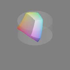
>

L, C and H are supposed to form a cylinder. There are some very small
sRGB bits poking outside of the cylinder. I guess I could show the bits
as well, as long as I explain what they are.

Also, I *did* make a mistake in the color conversion code. I was
clamping L, C and H to 0..100, 0..100 and 0..360 incorrectly. Once I
stopped clamping, the shape turned into what I have been expecting based
on earlier tests.

I've attached the final shape, with the outside sRGB bits trimmed off.

Mike
Post a reply to this message
Attachments:
Download 'cielch_color_solid_cylinder_isosurface.png' (24 KB)
Preview of image 'cielch_color_solid_cylinder_isosurface.png'
|
|
| |
| |
|
|
|
|
| |
| |
|
|
Am 25.11.2016 um 01:50 schrieb Mike Horvath:
> On 11/24/2016 6:43 PM, clipka wrote:
>> Am 24.11.2016 um 23:56 schrieb Mike Horvath:
>>
>>> Okay, the problem is that I want to use sRGB instead of RGB in the
>>> pigments. However, it seems to not be possible to multiply the sRGB
>>> colors and then average them like you can with regular RGB. Or is there
>>> a way to get this to work?
>>
>> Don't use sRGB when mucking around with colour spaces, unless you know
>> /exactly/ what you are doing. Colour space experts are smart enough to
>> specify colours in terms of linear light intensity, or otherwise
>> explicitly inform the readers.
>>
>
> The functions output sRGB colors with Illuminant = D65 and Observer = 2°
> (1931) according to one of the conversion websites that uses these
> formulas.
>
> I'd like the POV code to use sRGB as well.

Don't try to go via that route; it won't work with the approach I've
described.

Instead, in the function pipeline, insert a function to explicitly
convert from sRGB to RGB:

    3D cartesian -> Lch -> sRGB -> RGB -> "distance"

    3D cartesian -> Lch -> sRGB -> RGB -> pigments
Post a reply to this message
|
|
| |
| |
|
|
|
|
| |
| |
|
|
Am 25.11.2016 um 01:47 schrieb Mike Horvath:
> Thank you clipka! Everything is working perfectly now! Part of the
> problem was a bug in my conversion functions. Once I fixed it, I started
> getting the correct results.
>
> Do you mind if I put a LGPL license on the code an upload it to Wikipedia?

Feel free to do so.
Post a reply to this message
|
|
| |
| |
|
|
|
|
| |
| |
|
|
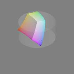
On 11/24/2016 8:28 PM, Mike Horvath wrote:
> I've attached the final shape, with the outside sRGB bits trimmed off.
>
> Mike

For comparison, here is the same image with the corner bits left in.

Mike
Post a reply to this message
Attachments:
Download 'cielch_color_solid_cylinder_isosurface.png' (24 KB)
Preview of image 'cielch_color_solid_cylinder_isosurface.png'
|
|
| |
| |
|
|
|
|
| |
| |
|
|
On 11/24/2016 8:33 PM, clipka wrote:
> Don't try to go via that route; it won't work with the approach I've
> described.
>
> Instead, in the function pipeline, insert a function to explicitly
> convert from sRGB to RGB:
>
>     3D cartesian -> Lch -> sRGB -> RGB -> "distance"
>
>     3D cartesian -> Lch -> sRGB -> RGB -> pigments
>

Do you have a function to convert between sRGB and RGB? One was not
included with ColorMine AFAIK.

Mike
Post a reply to this message
|
|
| |
| |
|
|
|
|
| |
| |
|
|
Am 25.11.2016 um 02:59 schrieb Mike Horvath:
> On 11/24/2016 8:33 PM, clipka wrote:
>> Don't try to go via that route; it won't work with the approach I've
>> described.
>>
>> Instead, in the function pipeline, insert a function to explicitly
>> convert from sRGB to RGB:
>>
>>     3D cartesian -> Lch -> sRGB -> RGB -> "distance"
>>
>>     3D cartesian -> Lch -> sRGB -> RGB -> pigments
>>
>
> Do you have a function to convert between sRGB and RGB? One was not
> included with ColorMine AFAIK.

No ready-made function; you'll need to piece things together from e.g.
https://en.wikipedia.org/wiki/SRGB.
Post a reply to this message
|
|
| |
| |
|
|
|
|
| |
| |
|
|
Am 25.11.2016 um 02:33 schrieb clipka:

> Instead, in the function pipeline, insert a function to explicitly
> convert from sRGB to RGB:
>
>     3D cartesian -> Lch -> sRGB -> RGB -> "distance"
>
>     3D cartesian -> Lch -> sRGB -> RGB -> pigments

I forgot: You won't necessarily need the sRGB->RGB step for the
"distance" function, as sRGB channel values of 0 and 1 map to RGB
channel values of 0 and 1, respectively.
Post a reply to this message
|
|
| |
| |
|
|
|
|
| |
| |
|
|
On 11/24/2016 9:11 PM, clipka wrote:
> Am 25.11.2016 um 02:59 schrieb Mike Horvath:
>> On 11/24/2016 8:33 PM, clipka wrote:
>>> Don't try to go via that route; it won't work with the approach I've
>>> described.
>>>
>>> Instead, in the function pipeline, insert a function to explicitly
>>> convert from sRGB to RGB:
>>>
>>>     3D cartesian -> Lch -> sRGB -> RGB -> "distance"
>>>
>>>     3D cartesian -> Lch -> sRGB -> RGB -> pigments
>>>
>>
>> Do you have a function to convert between sRGB and RGB? One was not
>> included with ColorMine AFAIK.
>
> No ready-made function; you'll need to piece things together from e.g.
> https://en.wikipedia.org/wiki/SRGB.
>

I am looking at the "The reverse transformation" section. Do I just need
to use the C_linear function?


Mike
Post a reply to this message
|
|
| |
| |
|
|
|
|
| |
| |
|
|
Am 25.11.2016 um 03:31 schrieb Mike Horvath:
> On 11/24/2016 9:11 PM, clipka wrote:
>> Am 25.11.2016 um 02:59 schrieb Mike Horvath:
>>> On 11/24/2016 8:33 PM, clipka wrote:
>>>> Don't try to go via that route; it won't work with the approach I've
>>>> described.
>>>>
>>>> Instead, in the function pipeline, insert a function to explicitly
>>>> convert from sRGB to RGB:
>>>>
>>>>     3D cartesian -> Lch -> sRGB -> RGB -> "distance"
>>>>
>>>>     3D cartesian -> Lch -> sRGB -> RGB -> pigments
>>>>
>>>
>>> Do you have a function to convert between sRGB and RGB? One was not
>>> included with ColorMine AFAIK.
>>
>> No ready-made function; you'll need to piece things together from e.g.
>> https://en.wikipedia.org/wiki/SRGB.
>>
>
> I am looking at the "The reverse transformation" section. Do I just need
> to use the C_linear function?

Yup, that's the one.
Post a reply to this message
|
|
| |
| |
|
|
|
|
| |
| |
|
|
On 11/24/2016 9:54 PM, clipka wrote:
> Am 25.11.2016 um 03:31 schrieb Mike Horvath:
>> On 11/24/2016 9:11 PM, clipka wrote:
>>> No ready-made function; you'll need to piece things together from e.g.
>>> https://en.wikipedia.org/wiki/SRGB.
>>>
>>
>> I am looking at the "The reverse transformation" section. Do I just need
>> to use the C_linear function?
>
> Yup, that's the one.
>
>

Okay, I will try that.

Mike
Post a reply to this message
|
|
| |
| |
|
|
|
|
| |
| |
|
|
>> May I ask the stupid question, "why not"?
>>
>> I would expect the Lch colour space to encompass all the RGB colour
>> space, so the boundaries of the latter should be sufficient to bound the
>> shape.
>>
>> My guess is that the issues you see with the shape are due to bogosities
>> in your colour conversion functions.
>>
>
> L, C and H are supposed to form a cylinder. There are some very small
> sRGB bits poking outside of the cylinder. I guess I could show the bits
> as well, as long as I explain what they are.

If sRGB is poking out of your cylinder, then Adobe RGB is going to poke
out even more, and the entire human visual range is going to be much
larger. Are you sure you've got the radius of your cylinder correct to
match your colour calculations? Also it would be surprising to me if the
human visual range came out exactly as a cylinder (after a brief glance
of the maths involved), are you sure about this?
Post a reply to this message
|
|
| |
| |
|
|
|
|
| |
| |
|
|
On 11/28/2016 3:23 AM, scott wrote:
>>> May I ask the stupid question, "why not"?
>>>
>>> I would expect the Lch colour space to encompass all the RGB colour
>>> space, so the boundaries of the latter should be sufficient to bound the
>>> shape.
>>>
>>> My guess is that the issues you see with the shape are due to bogosities
>>> in your colour conversion functions.
>>>
>>
>> L, C and H are supposed to form a cylinder. There are some very small
>> sRGB bits poking outside of the cylinder. I guess I could show the bits
>> as well, as long as I explain what they are.
>
> If sRGB is poking out of your cylinder, then Adobe RGB is going to poke
> out even more, and the entire human visual range is going to be much
> larger. Are you sure you've got the radius of your cylinder correct to
> match your colour calculations? Also it would be surprising to me if the
> human visual range came out exactly as a cylinder (after a brief glance
> of the maths involved), are you sure about this?
>

Yeah, I explain the mistake I made in this thread:

http://news.povray.org/583bd889%241%40news.povray.org

Mike
Post a reply to this message
|
|
| |
| |
|
|
|
|
| |
| |
|
|
On 11/28/2016 3:23 AM, scott wrote:
> Also it would be surprising to me if the
> human visual range came out exactly as a cylinder (after a brief glance
> of the maths involved), are you sure about this?
>

The human visual range has a very irregular shape.

https://en.wikipedia.org/wiki/File:Cie_Chart_with_sRGB_gamut_by_spigget.png

There's a lot of blank empty space around it in every color space. (The
one in the picture is called CIExyY I think.

I would like to learn how to plot this irregular shape in the near future.

Mike
Post a reply to this message
|
|
| |
| |
|
|
|
|
| |
| |
|
|
>> Also it would be surprising to me if the
>> human visual range came out exactly as a cylinder (after a brief glance
>> of the maths involved), are you sure about this?
>>
>
> The human visual range has a very irregular shape.
>
> https://en.wikipedia.org/wiki/File:Cie_Chart_with_sRGB_gamut_by_spigget.png
>
> There's a lot of blank empty space around it in every color space. (The
> one in the picture is called CIExyY I think.
>
> I would like to learn how to plot this irregular shape in the near future.

You just need the XYZ colour-matching functions in terms of wavelength.
Look here (just click the first "Submit" to get a basic table):

http://cvrl.ioo.ucl.ac.uk/cmfs.htm

This table then gives you the exact XYZ values for each pure wavelength.
XYZ is a linear representation of absolute colour, so you can do a lot
of math with them (eg adding, averaging, mixing etc).

To get the graph you linked to, you just need to calculate x and y for
each of those wavelengths.

x = X/(X+Y+Z)
y = Y/(X+Y+Z)

You'll then find that the x,y pairs give the outline of the graph you
linked to, which are the pure wavelengths. The internal area is formed
by mixing pure wavelengths, so roughly speaking the further you are away
from the boundary the more "wideband" the light is.
Post a reply to this message
|
|
| |
| |
|
|
|
|
| |
| |
|
|
On 11/28/2016 3:53 AM, scott wrote:
>>> Also it would be surprising to me if the
>>> human visual range came out exactly as a cylinder (after a brief glance
>>> of the maths involved), are you sure about this?
>>>
>>
>> The human visual range has a very irregular shape.
>>
>> https://en.wikipedia.org/wiki/File:Cie_Chart_with_sRGB_gamut_by_spigget.png
>>
>>
>> There's a lot of blank empty space around it in every color space. (The
>> one in the picture is called CIExyY I think.
>>
>> I would like to learn how to plot this irregular shape in the near
>> future.
>
> You just need the XYZ colour-matching functions in terms of wavelength.
> Look here (just click the first "Submit" to get a basic table):
>
> http://cvrl.ioo.ucl.ac.uk/cmfs.htm
>
> This table then gives you the exact XYZ values for each pure wavelength.
> XYZ is a linear representation of absolute colour, so you can do a lot
> of math with them (eg adding, averaging, mixing etc).
>
> To get the graph you linked to, you just need to calculate x and y for
> each of those wavelengths.
>
> x = X/(X+Y+Z)
> y = Y/(X+Y+Z)
>
> You'll then find that the x,y pairs give the outline of the graph you
> linked to, which are the pure wavelengths. The internal area is formed
> by mixing pure wavelengths, so roughly speaking the further you are away
> from the boundary the more "wideband" the light is.
>

Well, I don't understand that. Clipka did most of the work for me last
time...

Maybe you could take a look at the code on the LCH image's page on
Wikimedia and make some suggestions.

Mike
Post a reply to this message
|
|
| |
| |
|
|
|
|
| |
| |
|
|
On 11/28/2016 3:53 AM, scott wrote:
> You just need the XYZ colour-matching functions in terms of wavelength.
> Look here (just click the first "Submit" to get a basic table):
>
> http://cvrl.ioo.ucl.ac.uk/cmfs.htm
>
> This table then gives you the exact XYZ values for each pure wavelength.
> XYZ is a linear representation of absolute colour, so you can do a lot
> of math with them (eg adding, averaging, mixing etc).
>
> To get the graph you linked to, you just need to calculate x and y for
> each of those wavelengths.
>
> x = X/(X+Y+Z)
> y = Y/(X+Y+Z)
>
> You'll then find that the x,y pairs give the outline of the graph you
> linked to, which are the pure wavelengths. The internal area is formed
> by mixing pure wavelengths, so roughly speaking the further you are away
> from the boundary the more "wideband" the light is.
>


Also, I'm more interested in the 3-dimensional solid than the 2D
chromaticity diagram.

Mike
Post a reply to this message
|
|
| |
| |
|
|
|
|
| |
| |
|
|
> Also, I'm more interested in the 3-dimensional solid than the 2D
> chromaticity diagram.

The 3D solid of the Yxy shape is just the 2D shape you linked to
extruded upwards as a prism. That's why you don't normally see Yxy or
Yuv shown in 3D - it doesn't give any benefit over the 2D shape.
Post a reply to this message
|
|
| |
| |
|
|
|
|
| |
| |
|
|
On 28/11/2016 09:11, Mike Horvath wrote:
> On 11/28/2016 3:53 AM, scott wrote:
>>>> Also it would be surprising to me if the
>>>> human visual range came out exactly as a cylinder (after a brief glance
>>>> of the maths involved), are you sure about this?
>>>>
>>>
>>> The human visual range has a very irregular shape.
>>>
>>> https://en.wikipedia.org/wiki/File:Cie_Chart_with_sRGB_gamut_by_spigget.png
>>>
>>>
>>>
>>> There's a lot of blank empty space around it in every color space. (The
>>> one in the picture is called CIExyY I think.
>>>
>>> I would like to learn how to plot this irregular shape in the near
>>> future.
>>
>> You just need the XYZ colour-matching functions in terms of wavelength.
>> Look here (just click the first "Submit" to get a basic table):
>>
>> http://cvrl.ioo.ucl.ac.uk/cmfs.htm
>>
>> This table then gives you the exact XYZ values for each pure wavelength.
>> XYZ is a linear representation of absolute colour, so you can do a lot
>> of math with them (eg adding, averaging, mixing etc).
>>
>> To get the graph you linked to, you just need to calculate x and y for
>> each of those wavelengths.
>>
>> x = X/(X+Y+Z)
>> y = Y/(X+Y+Z)
>>
>> You'll then find that the x,y pairs give the outline of the graph you
>> linked to, which are the pure wavelengths. The internal area is formed
>> by mixing pure wavelengths, so roughly speaking the further you are away
>> from the boundary the more "wideband" the light is.
>>
>
> Well, I don't understand that.

Which bit?
Post a reply to this message
|
|
| |
| |
|
|
|
|
| |
| |
|
|
On 11/28/2016 4:24 AM, scott wrote:
>> Also, I'm more interested in the 3-dimensional solid than the 2D
>> chromaticity diagram.
>
> The 3D solid of the Yxy shape is just the 2D shape you linked to
> extruded upwards as a prism. That's why you don't normally see Yxy or
> Yuv shown in 3D - it doesn't give any benefit over the 2D shape.
>
>

I thought there was some tapering as the Y increases? This image
suggests that is the case.

http://www.math.ubc.ca/~cass/courses/m309-03a/m309-projects/bajwa/images/cie_3d.gif

Mike
Post a reply to this message
|
|
| |
| |
|
|
|
|
| |
| |
|
|
Am 28.11.2016 um 23:21 schrieb Mike Horvath:
> On 11/28/2016 4:24 AM, scott wrote:
>>> Also, I'm more interested in the 3-dimensional solid than the 2D
>>> chromaticity diagram.
>>
>> The 3D solid of the Yxy shape is just the 2D shape you linked to
>> extruded upwards as a prism. That's why you don't normally see Yxy or
>> Yuv shown in 3D - it doesn't give any benefit over the 2D shape.
>>
>>
>
> I thought there was some tapering as the Y increases? This image
> suggests that is the case.
>
> http://www.math.ubc.ca/~cass/courses/m309-03a/m309-projects/bajwa/images/cie_3d.gif

That's not the limit of the xyY space.

That's the theoretical limit of _reflective_ colours illuminated by
standard illuminant C, plotted in xyY space.
Post a reply to this message
|
|
| |
| |
|
|
|
|
| |
| |
|
|
On 11/28/2016 6:05 PM, clipka wrote:
>> I thought there was some tapering as the Y increases? This image
>> suggests that is the case.
>>
>> http://www.math.ubc.ca/~cass/courses/m309-03a/m309-projects/bajwa/images/cie_3d.gif
>
> That's not the limit of the xyY space.
>
> That's the theoretical limit of _reflective_ colours illuminated by
> standard illuminant C, plotted in xyY space.
>

Yes, that is fine. Not sure whether to use C or D65, though.

https://en.wikipedia.org/wiki/Illuminant_D65

These images on Wikipedia use D65, so I may just stick with that.

https://en.wikipedia.org/wiki/File:Cie_Chart_with_sRGB_gamut_by_spigget.png
https://en.wikipedia.org/wiki/File:CIE1931xy_gamut_comparison.svg
https://en.wikipedia.org/wiki/File:Lab_color_space.png (I think)


Mike
Post a reply to this message
|
|
| |
| |
|
|
|
|
| |
| |
|
|
Am 29.11.2016 um 00:33 schrieb Mike Horvath:
> On 11/28/2016 6:05 PM, clipka wrote:
>>> I thought there was some tapering as the Y increases? This image
>>> suggests that is the case.
>>>
>>>
http://www.math.ubc.ca/~cass/courses/m309-03a/m309-projects/bajwa/images/cie_3d.gif
>>>
>>
>> That's not the limit of the xyY space.
>>
>> That's the theoretical limit of _reflective_ colours illuminated by
>> standard illuminant C, plotted in xyY space.
>>
>
> Yes, that is fine. Not sure whether to use C or D65, though.
>
> https://en.wikipedia.org/wiki/Illuminant_D65
>
> These images on Wikipedia use D65, so I may just stick with that.
>
> https://en.wikipedia.org/wiki/File:Cie_Chart_with_sRGB_gamut_by_spigget.png
> https://en.wikipedia.org/wiki/File:CIE1931xy_gamut_comparison.svg
> https://en.wikipedia.org/wiki/File:Lab_color_space.png (I think)

The first two /show/ the D65 whitepoint (or, more precisely, its xy
coordinates), but other than that they're entirely independent of any
whitepoint. The first image even shows various other whitepoints.

As for the third image, I can't see where you got the idea that it has
anything to do with any whitepoint (except maybe for the fact that the
sRGB colour space, of which a few slices are shown, is defined such that
its "upper right" corner coincides with D65).

(Of course the image files themselves may also happen to be using a
colour encoding scheme that uses D65 as its nominal whitepoint, but I
don't think that's relevant in this context.)
Post a reply to this message
|
|
| |
| |
|
|
|
|
| |
| |
|
|
On 11/28/2016 6:59 PM, clipka wrote:
> Am 29.11.2016 um 00:33 schrieb Mike Horvath:
>> On 11/28/2016 6:05 PM, clipka wrote:
>>>> I thought there was some tapering as the Y increases? This image
>>>> suggests that is the case.
>>>>
>>>>
http://www.math.ubc.ca/~cass/courses/m309-03a/m309-projects/bajwa/images/cie_3d.gif
>>>>
>>>
>>> That's not the limit of the xyY space.
>>>
>>> That's the theoretical limit of _reflective_ colours illuminated by
>>> standard illuminant C, plotted in xyY space.
>>>
>>
>> Yes, that is fine. Not sure whether to use C or D65, though.
>>
>> https://en.wikipedia.org/wiki/Illuminant_D65
>>
>> These images on Wikipedia use D65, so I may just stick with that.
>>
>> https://en.wikipedia.org/wiki/File:Cie_Chart_with_sRGB_gamut_by_spigget.png
>> https://en.wikipedia.org/wiki/File:CIE1931xy_gamut_comparison.svg
>> https://en.wikipedia.org/wiki/File:Lab_color_space.png (I think)
>
> The first two /show/ the D65 whitepoint (or, more precisely, its xy
> coordinates), but other than that they're entirely independent of any
> whitepoint. The first image even shows various other whitepoints.
>
> As for the third image, I can't see where you got the idea that it has
> anything to do with any whitepoint (except maybe for the fact that the
> sRGB colour space, of which a few slices are shown, is defined such that
> its "upper right" corner coincides with D65).
>
> (Of course the image files themselves may also happen to be using a
> colour encoding scheme that uses D65 as its nominal whitepoint, but I
> don't think that's relevant in this context.)
>

Okay, sorry, I didn't think it was possible to compare different color
spaces like sRGB or Adobe RGB without selecting a white point.

Still, I would like to plot the horseshoe in 3D, anyway, using a
specific white point. (Or maybe multiple images, each with a different
white point.)

I don't think I'll figure out the math though.

Mike
Post a reply to this message
|
|
| |
| |
|
|
|
|
| |
| |
|
|
> Okay, sorry, I didn't think it was possible to compare different color
> spaces like sRGB or Adobe RGB without selecting a white point.

The "basis" of most colour spaces is XYZ. XYZ defines a colour exactly
(in terms of human perception) with just three numbers. The numbers are
linear in terms of physical power, so if you have two light sources in
very close proximity, you can simply add the two XYZ values to get the
resulting colour. What this means though is that doubling XYZ does not
give a perceived brightness twice as bright. Note there is no dependency
on any "white point", the three numbers alone are enough.

sRGB in turn defines exactly what "colour" full red, green and blue are
in terms of XYZ (you can look up the values). I say "colour", because
obviously you can scale all the values to get a brighter or dimmer
result, which is still technically sRGB. There is no white point assumed
or needed in the definitions of sRGB either. The same goes for Adobe
RGB, that defines a different set of RGB physical colours.

However, given that RGB are defined in sRGB exactly in terms of physical
colour, this then defines exactly what physical colour "white" in sRGB
is, ie if you add up equal ratios of the defined R,G and B, you get what
is "white" in the sRGB colour space. This happens to be very close to
D65, I assume by design.

> Still, I would like to plot the horseshoe in 3D, anyway, using a
> specific white point. (Or maybe multiple images, each with a different
> white point.)

Sorry this just doesn't make sense. The "horseshoe" shape is totally
independent of any white point, "using" a white point to plot it is
meaningless, the shape is the same and fixed by the XYZ values for each
wavelength of light only.
Post a reply to this message
|
|
| |
| |
|
|
|
|
| |
| |
|
|
Am 29.11.2016 um 13:52 schrieb scott:
>> Okay, sorry, I didn't think it was possible to compare different color
>> spaces like sRGB or Adobe RGB without selecting a white point.
>
> The "basis" of most colour spaces is XYZ. XYZ defines a colour exactly
> (in terms of human perception) with just three numbers. The numbers are
> linear in terms of physical power, so if you have two light sources in
> very close proximity, you can simply add the two XYZ values to get the
> resulting colour. What this means though is that doubling XYZ does not
> give a perceived brightness twice as bright. Note there is no dependency
> on any "white point", the three numbers alone are enough.
>
> sRGB in turn defines exactly what "colour" full red, green and blue are
> in terms of XYZ (you can look up the values). I say "colour", because
> obviously you can scale all the values to get a brighter or dimmer
> result, which is still technically sRGB. There is no white point assumed
> or needed in the definitions of sRGB either. The same goes for Adobe
> RGB, that defines a different set of RGB physical colours.
>
> However, given that RGB are defined in sRGB exactly in terms of physical
> colour, this then defines exactly what physical colour "white" in sRGB
> is, ie if you add up equal ratios of the defined R,G and B, you get what
> is "white" in the sRGB colour space. This happens to be very close to
> D65, I assume by design.

This is not quite true.

sRGB does /not/ explicitly specify what full red, green and blue are.

What sRGB does define is the _xy coordinates_ - i.e. the absolute hue
and saturation - of red, green and blue (aka the "primaries"). This can
be visualized as defining the direction (but not the "length") of the
red, green and blue axes in XYZ space.

sRGB also /does/ explicitly define the _xy coordinates_ of the so-called
"illuminant whitepoint" - i.e. which defines what colours are nominally
"neutral", i.e. entirely desaturated - and also defines that such
neutral colours are to be represented by the red, green and blue
channels all set to the same value (which is typical for RGB colour
models). This can be visualized as defining the direction (but again not
the "length") of the RGB "cube"'s diagonal in XYZ space.

sRGB also /does/ explicitly define the _Y coordinate_ - i.e. the
luminance - of the brightest representable colour: 80 cd/m^2; however,
not everyone adheres to this.

sRGB also defines a host of other things that make matters even more
complicated, namely the "image surround", as well three properties for
both the "encoding" and "typical viewing" conditions: "ambient
illuminance level", "ambient white point" (which is D50, not D65), and
"viewing flare". (And no, don't ask me to explain what these parameters
mean - I barely understand those myself.)


>> Still, I would like to plot the horseshoe in 3D, anyway, using a
>> specific white point. (Or maybe multiple images, each with a different
>> white point.)
>
> Sorry this just doesn't make sense. The "horseshoe" shape is totally
> independent of any white point, "using" a white point to plot it is
> meaningless, the shape is the same and fixed by the XYZ values for each
> wavelength of light only.

It /does/ make some sense to plot the 3D extension of the horseshoe for
pigment colours under a given illuminant.

It should be noted however that such a plot is non-trivial: It does
/not/ suffice to specify the xy coordinates of the illuminant; the
entire colour spectrum needs to be considered instead. For example with
illuminants from the F series (fluorescent lighting) we can probably
expect the 3D shape to show a distinctive "fingerprint" of the
illuminant's spectral emission lines (though I'm not sure how exactly
this fingerprint would look like).
Post a reply to this message
|
|
| |
| |
|
|
|
|
| |
| |
|
|
On 11/29/2016 11:42 AM, clipka wrote:
> It should be noted however that such a plot is non-trivial: It does
> /not/ suffice to specify the xy coordinates of the illuminant; the
> entire colour spectrum needs to be considered instead. For example with
> illuminants from the F series (fluorescent lighting) we can probably
> expect the 3D shape to show a distinctive "fingerprint" of the
> illuminant's spectral emission lines (though I'm not sure how exactly
> this fingerprint would look like).
>

Okay, you've convinced me to give up!

I like to code but suck at math.

;)

Mike
Post a reply to this message
|
|
| |
| |
|
|
|
|
| |
| |
|
|
On 11/29/2016 11:42 AM, clipka wrote:
> sRGB also defines a host of other things that make matters even more
> complicated, namely the "image surround", as well three properties for
> both the "encoding" and "typical viewing" conditions: "ambient
> illuminance level", "ambient white point" (which is D50, not D65), and
> "viewing flare". (And no, don't ask me to explain what these parameters
> mean - I barely understand those myself.)

EasyRGB defaults to "Daylight". Isn't that D65?

http://www.easyrgb.com/index.php?X=CALC

ColorMine uses these values:

#declare XYZWhiteReference = color <95.047,100.000,108.883>;
#declare XYZEpsilon = 0.008856;
#declare XYZKappa = 903.3;

Which illuminant does that correspond to? I have no clue, and assumed it
was D65 as well.

Mike
Post a reply to this message
|
|
| |
| |
|
|
|
|
| |
| |
|
|
On 11/29/2016 7:52 AM, scott wrote:
> The "basis" of most colour spaces is XYZ. XYZ defines a colour exactly
> (in terms of human perception) with just three numbers. The numbers are
> linear in terms of physical power, so if you have two light sources in
> very close proximity, you can simply add the two XYZ values to get the
> resulting colour. What this means though is that doubling XYZ does not
> give a perceived brightness twice as bright. Note there is no dependency
> on any "white point", the three numbers alone are enough.

The LAB > XYZ > RGB conversion algorithms I am using simply don't
*function* without setting a white point, though.

http://colormine.org/

Mike
Post a reply to this message
|
|
| |
| |
|
|
|
|
| |
| |
|
|
Am 29.11.2016 um 18:12 schrieb Mike Horvath:
> On 11/29/2016 11:42 AM, clipka wrote:
>> sRGB also defines a host of other things that make matters even more
>> complicated, namely the "image surround", as well three properties for
>> both the "encoding" and "typical viewing" conditions: "ambient
>> illuminance level", "ambient white point" (which is D50, not D65), and
>> "viewing flare". (And no, don't ask me to explain what these parameters
>> mean - I barely understand those myself.)
>
> EasyRGB defaults to "Daylight". Isn't that D65?

"Daylight" could be D65 - but it could just as well be any other member
of the "Illuminant D series" (D50, D55, D65, D75), each of which
simulates daylight at another time of day, or even illuminant B or C,
both of which were designed as daylight simulations (although that's
unlikely, since these illuminants have been deprecated).

> http://www.easyrgb.com/index.php?X=CALC

Any colour converter that supports a colour space named "RGB" (or "CMY"
or "CMYK", for that matter) without further qualification isn't worth a
rotten bit.

"RGB", "CMY" and "CMYK" aren't colour models - they are colour model
_families_. The minimum additional information required to convert
colours from one of these models into any other model are the colour
coordinates of the primaries, the whitepoint and - since most real-life
RGB colour models don't use linear encoding - the transfer function (aka
"gamma"). Or the official name of the specific member of the family,
which defines these properties via the model's official standard.

For example, "RGB" could be "sRGB" - or it oculd be "CIE RGB", which is
a totally different beast.

> ColorMine uses these values:
>
> #declare XYZWhiteReference = color <95.047,100.000,108.883>;
> [...]
>
> Which illuminant does that correspond to? I have no clue, and assumed it
> was D65 as well.

XYZ (95.047,100,108.883) corresponds to xy (95.047,100)/303.93 =
(0.3127,0.3290), which is indeed D65 (presuming XYZ is CIE 1931 XYZ).

(Don't ask me what XYZEpsilon and XYZKappa are.)
Post a reply to this message
|
|
| |
| |
|
|
|
|
| |
| |
|
|
Am 29.11.2016 um 18:26 schrieb Mike Horvath:
> On 11/29/2016 7:52 AM, scott wrote:
>> The "basis" of most colour spaces is XYZ. XYZ defines a colour exactly
>> (in terms of human perception) with just three numbers. The numbers are
>> linear in terms of physical power, so if you have two light sources in
>> very close proximity, you can simply add the two XYZ values to get the
>> resulting colour. What this means though is that doubling XYZ does not
>> give a perceived brightness twice as bright. Note there is no dependency
>> on any "white point", the three numbers alone are enough.
>
> The LAB > XYZ > RGB conversion algorithms I am using simply don't
> *function* without setting a white point, though.
>
> http://colormine.org/

Of course not. You can't convert to RGB unless you know /what/ RGB model
you're converting to, and whitespace is one of the defining factors.

You will also need to specify the colour primaries, if the conversion
algorithm is any good.
Post a reply to this message
|
|
| |
| |
|
|
|
|
| |
| |
|
|
> sRGB does /not/ explicitly specify what full red, green and blue are.
>
> What sRGB does define is the _xy coordinates_ - i.e. the absolute hue
> and saturation - of red, green and blue (aka the "primaries"). This can
> be visualized as defining the direction (but not the "length") of the
> red, green and blue axes in XYZ space.
>
> sRGB also /does/ explicitly define the _xy coordinates_ of the so-called
> "illuminant whitepoint" - i.e. which defines what colours are nominally
> "neutral", i.e. entirely desaturated - and also defines that such
> neutral colours are to be represented by the red, green and blue
> channels all set to the same value (which is typical for RGB colour
> models). This can be visualized as defining the direction (but again not
> the "length") of the RGB "cube"'s diagonal in XYZ space.
>
> sRGB also /does/ explicitly define the _Y coordinate_ - i.e. the
> luminance - of the brightest representable colour: 80 cd/m^2; however,
> not everyone adheres to this.

The exact definition may not be as I simplified to, but the point is the
same. The "output" of the spec is that XYZ for each of R,G,B are numbers
that are always the same, there is no dependence on some externally
provided white point information.

The only additional piece of information you may want to know is if it
has been scaled above the 80 cd/m^2 standard. eg with an "sRGB" computer
monitor these are typically nearer 300 cd/m^2, but knowing that you can
calculate the true colours, there is no need for any additional white point.
Post a reply to this message
|
|
| |
| |
|
|
|
|
| |
| |
|
|
Am 30.11.2016 um 09:15 schrieb scott:
>> sRGB does /not/ explicitly specify what full red, green and blue are.
>>
>> What sRGB does define is the _xy coordinates_ - i.e. the absolute hue
>> and saturation - of red, green and blue (aka the "primaries"). This can
>> be visualized as defining the direction (but not the "length") of the
>> red, green and blue axes in XYZ space.
>>
>> sRGB also /does/ explicitly define the _xy coordinates_ of the so-called
>> "illuminant whitepoint" - i.e. which defines what colours are nominally
>> "neutral", i.e. entirely desaturated - and also defines that such
>> neutral colours are to be represented by the red, green and blue
>> channels all set to the same value (which is typical for RGB colour
>> models). This can be visualized as defining the direction (but again not
>> the "length") of the RGB "cube"'s diagonal in XYZ space.
>>
>> sRGB also /does/ explicitly define the _Y coordinate_ - i.e. the
>> luminance - of the brightest representable colour: 80 cd/m^2; however,
>> not everyone adheres to this.
>
> The exact definition may not be as I simplified to, but the point is the
> same. The "output" of the spec is that XYZ for each of R,G,B are numbers
> that are always the same, there is no dependence on some externally
> provided white point information.

You're right in that respect. The above information was mainly for the
records.
Post a reply to this message
|
|
| |
| |
|
|
|
|
| |
| |
|
|
Am 29.11.2016 um 18:08 schrieb Mike Horvath:
> On 11/29/2016 11:42 AM, clipka wrote:
>> It should be noted however that such a plot is non-trivial: It does
>> /not/ suffice to specify the xy coordinates of the illuminant; the
>> entire colour spectrum needs to be considered instead. For example with
>> illuminants from the F series (fluorescent lighting) we can probably
>> expect the 3D shape to show a distinctive "fingerprint" of the
>> illuminant's spectral emission lines (though I'm not sure how exactly
>> this fingerprint would look like).
>>
>
> Okay, you've convinced me to give up!
>
> I like to code but suck at math.
>
> ;)

You've made me curious though, so see povray.binaries.animations for a
series of animated CIE xyY gamuts of various illuminants.

Using meshes instead of isosurfaces, because the latter would have been
virtually impossible to manage.

Even then it took me several attempts before I knew how the problem
could be tackled.


I was rather surprised at first to see that the shape isn't convex,
until I realized that it would only be convex in CIE XYZ space. But then
it becomes rather boring, and its relation to the xy horseshoe less obvious.
Post a reply to this message
|
|
| |
| |
|
|
|
|
| |
|
|