|
|
|
|
|
|
| |
| |
|
|
|
|
| |
| |
|
|
> That's pretty mental, by the way. But what the hell *is* it??
A metal case that goes on the back of an LCD display. Mainly to avoid
electrical interference between the LCD and other parts in the car, but also
for mechanical protection. The pressed out lump in the centre is where
quite a few high components on the PCB are located, so it needs to provide
space for them, then there's two holes for connectors to go through, a
couple of features to make a good ground connection to the PCB, and various
clips and holes around the edge to securely fasten to the rest of the LCD.
Oh and of course some holes for screws to go through so the thing can be
fitted to the rest of the car!
> Also... how do you make something like that? It looks like you'd either
> have to mould it, or take a sheet of metal, bend it around a bit, cut
> windows and drill holes in it...
Yeh it's pressed metal, so you start with a blank sheet and then it goes
through a series of tools that bend and cut certain bits until the final
shape is produced (IIRC there's about 7 or 8 stages usually), no drilling -
the tools have sharp bits that cut the holes and other shapes, just like a
big hole-punch!
Post a reply to this message
|
|
| |
| |
|
|
|
|
| |
| |
|
|
>> That's pretty mental, by the way. But what the hell *is* it??
>
> A metal case that goes on the back of an LCD display. Mainly to avoid
> electrical interference between the LCD and other parts in the car, but
> also for mechanical protection. The pressed out lump in the centre is
> where quite a few high components on the PCB are located, so it needs to
> provide space for them, then there's two holes for connectors to go
> through, a couple of features to make a good ground connection to the
> PCB, and various clips and holes around the edge to securely fasten to
> the rest of the LCD. Oh and of course some holes for screws to go
> through so the thing can be fitted to the rest of the car!
...it's times like this that I realise other people have way more
interesting jobs than I do! ;-)
> Yeh it's pressed metal, so you start with a blank sheet and then it goes
> through a series of tools that bend and cut certain bits until the final
> shape is produced (IIRC there's about 7 or 8 stages usually)
Damn. That process must take some designing!
> no drilling - the tools have sharp bits that cut the holes and other
> shapes, just like a big hole-punch!
Heh. How thick is the metal??
Post a reply to this message
|
|
| |
| |
|
|
|
|
| |
| |
|
|
> I've often wondered how CAD manages to produce complex, detailed 3D
> objects. I have yet to see a modeller that makes it feasible to produce
> any moderately complex 3D shape.
Yes, but have you actually seen anyone using commercial CAD software like
Catia or Pro/Engineer? You know, the software that people who build planes
and cars use?
eg here is a screen shot of a model from Boeing:
http://www.nextcraft.com/media/aviation_technology/military_nasa/B737_catia_big.jpg
It's a bit more suited to doing this sort of stuff than a modeller like 3D
Studio or Blender. It is more focussed on dimensions and model hierarchy,
and less on the graphical appearance (most of the time you are just using
plane gourard shading or even wireframe if you need to see certain details).
For example, the modelling process in a CAD package for that metal case I
posted would be something like this:
- Draw the outline cuboid shape
- Add on extrusions and cuts for any bumps and dips
- Add rounds to any edges
- Shell the model (this leaves a shell of specified thickness, 2 clicks in
CAD)
- Add in holes where necessary
- Add more rounds
- Add in any clip geometry
The CAD software remembers all that history used to generate the model, so
you can always go back and change the shell thickness and everything else
updates (or move the position of a bump etc).
Post a reply to this message
|
|
| |
| |
|
|
|
|
| |
| |
|
|
>> I've often wondered how CAD manages to produce complex, detailed 3D
>> objects. I have yet to see a modeller that makes it feasible to
>> produce any moderately complex 3D shape.
>
> Yes, but have you actually seen anyone using commercial CAD software
> like Catia or Pro/Engineer? You know, the software that people who build
> planes and cars use?
No. And that's what I've always wondered about - given the complexity of
the stuff these guys produce, their modelling tools must surely be more
sophisticated in some way.
> eg here is a screen shot of a model from Boeing:
>
> http://www.nextcraft.com/media/aviation_technology/military_nasa/B737_catia_big.jpg
OK, that's fairly crazy.
> For example, the modelling process in a CAD package for that metal case
> I posted would be something like this:
> - Draw the outline cuboid shape
> - Add on extrusions and cuts for any bumps and dips
> - Add rounds to any edges
> - Shell the model (this leaves a shell of specified thickness, 2 clicks
> in CAD)
> - Add in holes where necessary
> - Add more rounds
> - Add in any clip geometry
>
> The CAD software remembers all that history used to generate the model,
> so you can always go back and change the shell thickness and everything
> else updates (or move the position of a bump etc).
I'd almost consider trying to track down some software like this - if it
wasn't for the fact that I keep hearing that it costs a fortune and
crashes routinely...
Post a reply to this message
|
|
| |
| |
|
|
|
|
| |
| |
|
|
>> Yeh it's pressed metal, so you start with a blank sheet and then it goes
>> through a series of tools that bend and cut certain bits until the final
>> shape is produced (IIRC there's about 7 or 8 stages usually)
>
> Damn. That process must take some designing!
Yes, that's why the tools have ridiculous prices, usually with 6 or even
sometimes 7 figures! And then you realise why the guy gets annoyed when you
ask for +/-0.1mm tolerance between two specific points :-)
>> no drilling - the tools have sharp bits that cut the holes and other
>> shapes, just like a big hole-punch!
>
> Heh. How thick is the metal??
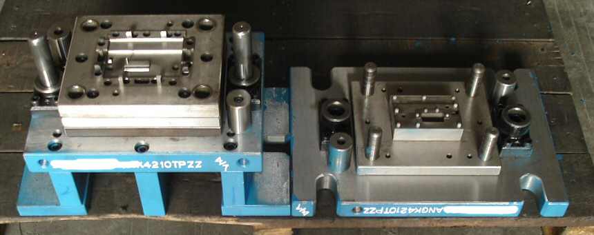
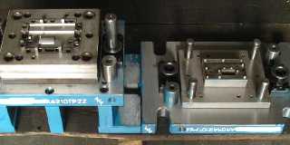
Usually 0.3 - 0.6 mm depending on how big it is. The tools are quite beefy
though, see attached (that is just stage 4 out of 7), all the intricate
detail in the middle is what actually makes the cuts and folds, the inner
working of each stage can be quite complex with spring loaded plates and
levers etc to do the bending correctly as the two halfs come together.
Post a reply to this message
Attachments:
Download 'image1.jpg' (29 KB)
Preview of image 'image1.jpg'
|
|
| |
| |
|
|
|
|
| |
| |
|
|
> I'd almost consider trying to track down some software like this - if it
> wasn't for the fact that I keep hearing that it costs a fortune and
> crashes routinely...
There used to be a really good free version of Pro/Engineer called
Pro/Desktop, but unfortunately they stopped supporting it and I think you
needed to get some registration key before it would work on your machine.
Shame, because it was really nice and there really is no other decent free
CAD software out there, and as you pointed out the commerical software is
really expensive so not really suitable for home tinkering.
Post a reply to this message
|
|
| |
| |
|
|
|
|
| |
| |
|
|
>> Damn. That process must take some designing!
>
> Yes, that's why the tools have ridiculous prices, usually with 6 or even
> sometimes 7 figures! And then you realise why the guy gets annoyed when
> you ask for +/-0.1mm tolerance between two specific points :-)
actually. :-} I imagine the inside of one of those is somewhat more
complicated than a flat metal bracket.
>> Heh. How thick is the metal??
>
> Usually 0.3 - 0.6 mm depending on how big it is.
How strong is the metal? And how heavy? I mean, I guess it varies by
which particular alloy you use... Presumably somebody has already
tabulated this data? I imagine for a sufficiently small part, you can't
physically apply enough torque to it to actually bend it. (In normal
circumstances, at least.) I guess that's why small twigs sometimes seem
"stronger" than large branches...
> The tools are quite
> beefy though, see attached (that is just stage 4 out of 7), all the
> intricate detail in the middle is what actually makes the cuts and
> folds, the inner working of each stage can be quite complex with spring
> loaded plates and levers etc to do the bending correctly as the two
> halfs come together.
Hmm. And now I'm wondering... how do you manufacture the tool you use to
manufacture the thing you actually wanted to make in the first place? :-D
Post a reply to this message
|
|
| |
| |
|
|
|
|
| |
| |
|
|
>> I'd almost consider trying to track down some software like this - if
>> it wasn't for the fact that I keep hearing that it costs a fortune and
>> crashes routinely...
>
> There used to be a really good free version of Pro/Engineer called
> Pro/Desktop, but unfortunately they stopped supporting it and I think
> you needed to get some registration key before it would work on your
> machine. Shame, because it was really nice and there really is no other
> decent free CAD software out there,
Mmm. Pitty.
I suppose notionally if I knew how it works, I could write something
myself. OTOH, I have yet to write a working Tic-Tac-Toe program, so...
maybe not. :-/
> and as you pointed out the
> commerical software is really expensive so not really suitable for home
> tinkering.
I guess they figure that if you're going to spent 7 figures *per tool*
to make your multi-part item, a few extra digits for a CAD package is
nothing... ;-)
Post a reply to this message
|
|
| |
| |
|
|
|
|
| |
| |
|
|
> I suppose notionally if I knew how it works, I could write something
> myself.
I often thought about this too, this is usually what is used internally to
represent the shapes:
http://en.wikipedia.org/wiki/Boundary_representation
But it just gets too complicated too quickly when you have to calculate CSG
operations, adding rounds to edges etc, it's much harder than raytracing
CSG!
Post a reply to this message
|
|
| |
| |
|
|
|
|
| |
| |
|
|
> How strong is the metal? And how heavy? I mean, I guess it varies by which
> particular alloy you use... Presumably somebody has already tabulated this
> data?
Of course.
> I imagine for a sufficiently small part, you can't physically apply enough
> torque to it to actually bend it. (In normal circumstances, at least.)
Why not? What is going to limit how much torque you can apply, you just get
a machine with a beefier tool and press attached.
> I guess that's why small twigs sometimes seem "stronger" than large
> branches...
That's probably just because you can't get a good grip of the twig to apply
enough torque, sandwich it between two huge steel plates, both with a step
in them, then apply 10 tons of force and I think you will see that the twig
can bend :-)
> Hmm. And now I'm wondering... how do you manufacture the tool you use to
> manufacture the thing you actually wanted to make in the first place? :-D
Some guy sitting at a computerised milling machine I would imagine.
And yes, how do you make that, etc etc I think at the beginning someone had
to make something with their bare hands :-)
Post a reply to this message
|
|
| |
| |
|
|
|
|
| |