 |
|
|
|
|
|
| |
| |
|
|
|
|
| |
| |
|
|
Hola,
having a bit of trouble coming up with a couple of rolled up maps for my
scene. i've created a compass, dividers, cartographers loupe, and a table
with a flat interesting map (image_map) on top of the table. i've tried a
series on concentric cylinders (slightly unevenly scaled) with an image map
wrappped around the outer cylinder .... but it looks hokey. any ideas?
Ciao Jim
Post a reply to this message
|
|
| |
| |
|
|
|
|
| |
| |
|
|
> having a bit of trouble coming up with a couple of rolled up maps for my
> scene. i've created a compass, dividers, cartographers loupe, and a table
> with a flat interesting map (image_map) on top of the table. i've tried a
> series on concentric cylinders (slightly unevenly scaled) with an image
> map wrappped around the outer cylinder .... but it looks hokey. any ideas?
>
> Ciao Jim
>
If you are good with math and macros, you could try creating a procedural
mesh. This also will give the advantage of being able to uv map it.
-tgq
Post a reply to this message
|
|
| |
| |
|
|
|
|
| |
| |
|
|
Wasn't it Jim Holsenback who wrote:
>Hola,
>
>having a bit of trouble coming up with a couple of rolled up maps for my
>scene. i've created a compass, dividers, cartographers loupe, and a table
>with a flat interesting map (image_map) on top of the table. i've tried a
>series on concentric cylinders (slightly unevenly scaled) with an image map
>wrappped around the outer cylinder .... but it looks hokey. any ideas?
You might be able to tweak this into what you need.
It uses Ingo Janssen's Param.inc macro, which creates a mesh with uv
mapping, so it should be possible to paint a map onto it
Get param.inc from http://members.home.nl/seedseven/
global_settings {assumed_gamma 1.0}
#declare R1=0.2; //inner radius right end
#declare R2=1; //outer radius right end
#declare R3=0.1; //inner radius left end
#declare R4=1.5; //outer radius left end
#declare DX=3; //length of straight bit
#declare F1 = 5*pi; //frequency of right end: use (4n+1)*pi
#declare F2 = 14*pi; //frequency of left end: use (4n+2)*pi
camera { location <-5, 3, -10> look_at <-DX/2,0,0> angle 28}
light_source {<-100,200,-500> colour rgb 1}
// An open 2D spline
#declare S = function {
spline {
linear_spline
// right end
#declare T=0;
#while (T<0.5)
#declare X=cos(T*F1)*((R1*(0.5-T))+(R2*T));
#declare Y=-sin(T*F1)*((R1*(0.5-T))+(R2*T));
T, <X,Y>,
#declare T=T+0.002;
#end
// left end
#while (T<1)
#declare X=sin(T*F2)*((R4*(1-T))+(R3*(T-0.5))) - DX;
#declare Y=cos(T*F2)*((R4*(1-T))+(R3*(T-0.5)));
T, <X,Y>,
#declare T=T+0.002;
#end
}
}
#declare Fx = function(u,v) {S(u).x}
#declare Fy = function(u,v) {S(u).y}
#declare Fz = function(u,v) {v}
#include "param.inc"
object {Parametric(Fx,Fy,Fz,<0,-2>,<1,2>,400,2,"")
pigment {rgb 1}
}
--
Mike Williams
Gentleman of Leisure
Post a reply to this message
|
|
| |
| |
|
|
|
|
| |
| |
|
|
"Mike Williams" <nos### [at] econym demoncouk> wrote in message
news:Um8### [at] econymdemoncouk...
> You might be able to tweak this into what you need.
haha .... how come i figured it would be you to reply ....
> It uses Ingo Janssen's Param.inc macro, which creates a mesh with uv
> mapping, so it should be possible to paint a map onto it
>
> Get param.inc from http://members.home.nl/seedseven/
i took a look at this sometime ago and went .... what???!??? now that i've
been pov'ing for a bit i'm feeling a bit more "froggy" so i'll give 'er a
leap .... thanks again Mike .... Ciao
> global_settings {assumed_gamma 1.0}
>
> #declare R1=0.2; //inner radius right end
> #declare R2=1; //outer radius right end
> #declare R3=0.1; //inner radius left end
> #declare R4=1.5; //outer radius left end
> #declare DX=3; //length of straight bit
> #declare F1 = 5*pi; //frequency of right end: use (4n+1)*pi
> #declare F2 = 14*pi; //frequency of left end: use (4n+2)*pi
>
> camera { location <-5, 3, -10> look_at <-DX/2,0,0> angle 28}
> light_source {<-100,200,-500> colour rgb 1}
>
> // An open 2D spline
> #declare S = function {
> spline {
> linear_spline
> // right end
> #declare T=0;
> #while (T<0.5)
> #declare X=cos(T*F1)*((R1*(0.5-T))+(R2*T));
> #declare Y=-sin(T*F1)*((R1*(0.5-T))+(R2*T));
> T, <X,Y>,
> #declare T=T+0.002;
> #end
> // left end
> #while (T<1)
> #declare X=sin(T*F2)*((R4*(1-T))+(R3*(T-0.5))) - DX;
> #declare Y=cos(T*F2)*((R4*(1-T))+(R3*(T-0.5)));
> T, <X,Y>,
> #declare T=T+0.002;
> #end
> }
> }
>
>
> #declare Fx = function(u,v) {S(u).x}
> #declare Fy = function(u,v) {S(u).y}
> #declare Fz = function(u,v) {v}
>
> #include "param.inc"
>
> object {Parametric(Fx,Fy,Fz,<0,-2>,<1,2>,400,2,"")
> pigment {rgb 1}
> }
>
> --
> Mike Williams
> Gentleman of Leisure demoncouk> wrote in message
news:Um8### [at] econymdemoncouk...
> You might be able to tweak this into what you need.
haha .... how come i figured it would be you to reply ....
> It uses Ingo Janssen's Param.inc macro, which creates a mesh with uv
> mapping, so it should be possible to paint a map onto it
>
> Get param.inc from http://members.home.nl/seedseven/
i took a look at this sometime ago and went .... what???!??? now that i've
been pov'ing for a bit i'm feeling a bit more "froggy" so i'll give 'er a
leap .... thanks again Mike .... Ciao
> global_settings {assumed_gamma 1.0}
>
> #declare R1=0.2; //inner radius right end
> #declare R2=1; //outer radius right end
> #declare R3=0.1; //inner radius left end
> #declare R4=1.5; //outer radius left end
> #declare DX=3; //length of straight bit
> #declare F1 = 5*pi; //frequency of right end: use (4n+1)*pi
> #declare F2 = 14*pi; //frequency of left end: use (4n+2)*pi
>
> camera { location <-5, 3, -10> look_at <-DX/2,0,0> angle 28}
> light_source {<-100,200,-500> colour rgb 1}
>
> // An open 2D spline
> #declare S = function {
> spline {
> linear_spline
> // right end
> #declare T=0;
> #while (T<0.5)
> #declare X=cos(T*F1)*((R1*(0.5-T))+(R2*T));
> #declare Y=-sin(T*F1)*((R1*(0.5-T))+(R2*T));
> T, <X,Y>,
> #declare T=T+0.002;
> #end
> // left end
> #while (T<1)
> #declare X=sin(T*F2)*((R4*(1-T))+(R3*(T-0.5))) - DX;
> #declare Y=cos(T*F2)*((R4*(1-T))+(R3*(T-0.5)));
> T, <X,Y>,
> #declare T=T+0.002;
> #end
> }
> }
>
>
> #declare Fx = function(u,v) {S(u).x}
> #declare Fy = function(u,v) {S(u).y}
> #declare Fz = function(u,v) {v}
>
> #include "param.inc"
>
> object {Parametric(Fx,Fy,Fz,<0,-2>,<1,2>,400,2,"")
> pigment {rgb 1}
> }
>
> --
> Mike Williams
> Gentleman of Leisure
Post a reply to this message
|
|
| |
| |
|
|
|
|
| |
| |
|
|
"Mike Williams" <nos### [at] econymdemoncouk> wrote in message
news:Um8### [at] econymdemoncouk...
> You might be able to tweak this into what you need.
>
> It uses Ingo Janssen's Param.inc macro, which creates a mesh with uv
> mapping, so it should be possible to paint a map onto it
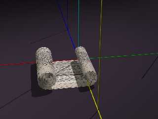
Yep ... it worked .... kind of .... I used the following:
texture {
uv_mapping pigment {
image_map {
jpeg "1917.jpg"
map_type 0
interpolate 4
once
}
}}
as you can see from the attached image it wraps the image fine around the
rolled up ends but not on the flat part in the middle. scale, rotate, or
translate issues? maybe this isn't possible, but notice how the image is
wrapped on both sides of the object (front and back of the map object)
Thanks!
Post a reply to this message
Attachments:
Download 'scratch.jpg' (71 KB)
Preview of image 'scratch.jpg'
|
|
| |
| |
|
|
|
|
| |
| |
|
|
"Jim Holsenback" <jho### [at] hotmailcom> wrote:
> as you can see from the attached image it wraps the image fine around the
> rolled up ends but not on the flat part in the middle. scale, rotate, or
> translate issues? maybe this isn't possible, but notice how the image is
> wrapped on both sides of the object (front and back of the map object)
>
> Thanks!
Your likely culprit here is that the size of the mesh in the flat area is
larger than in the rolled areas, causing the uv mapping for those triangle
sto be stretched. Even though it is flat between the rolled ends, try to
keep the mesh in this area approximately the same size as in the ends.
-tgq
Post a reply to this message
|
|
| |
| |
|
|
|
|
| |
| |
|
|
Wasn't it Trevor G Quayle who wrote:
>"Jim Holsenback" <jho### [at] hotmailcom> wrote:
>> as you can see from the attached image it wraps the image fine around the
>> rolled up ends but not on the flat part in the middle. scale, rotate, or
>> translate issues? maybe this isn't possible, but notice how the image is
>> wrapped on both sides of the object (front and back of the map object)
>>
>> Thanks!
>
>Your likely culprit here is that the size of the mesh in the flat area is
>larger than in the rolled areas, causing the uv mapping for those triangle
>sto be stretched. Even though it is flat between the rolled ends, try to
>keep the mesh in this area approximately the same size as in the ends.
The problem actually is that the spline control points are no evenly
spaced. I used control points from 0.0 to 0.5 for the rolled area at one
end, and control points 0.5002 to 1.0 for the rolled area at the other
end. I hadn't realized that the uv mapping would follow the control
point spacing.
The whole thing would need to be redesigned to have control points that
are evenly distributed along the spline. It turns out to be quite tricky
to write it so that the spline is generated with evenly spaced control
points.
Is there a utility that will take a spline and reorganize the control
points to be evenly spread without changing the shape?
--
Mike Williams
Gentleman of Leisure
Post a reply to this message
|
|
| |
| |
|
|
|
|
| |
| |
|
|
Mike Williams wrote:
> Is there a utility that will take a spline and reorganize the control
> points to be evenly spread without changing the shape?
I think it would look better if the flat part wasn't completely flat. It
should have little wrinkles in it and such, as it has been rolled up for
a while, yes? :-)
--
Darren New / San Diego, CA, USA (PST)
Luke, the Force is a powerful ally,
second only to The QuickSave.
Post a reply to this message
|
|
| |
| |
|
|
|
|
| |
| |
|
|
> The problem actually is that the spline control points are no evenly
> spaced. I used control points from 0.0 to 0.5 for the rolled area at one
> end, and control points 0.5002 to 1.0 for the rolled area at the other
> end. I hadn't realized that the uv mapping would follow the control
> point spacing.
didn't notice it was a spline, but same concept
>
> The whole thing would need to be redesigned to have control points that
> are evenly distributed along the spline. It turns out to be quite tricky
> to write it so that the spline is generated with evenly spaced control
> points.
>
> Is there a utility that will take a spline and reorganize the control
> points to be evenly spread without changing the shape?
try this procedural version I put together for you, gives approximately
equal spacing for the control points:
//start
#declare MapLen = 300; //overall length of map
#declare LLen = 150; //length rolled up at left
#declare RLen = 100; //length rolled up at right
#declare MLen = MapLen-LLen-RLen; //flat secton in middle
#declare RL= 10; //outer radius of left roll
#declare SL= 1; //spacing between roll layers on left
#declare RR= 7; //outer radius of right roll
#declare SR= 1.5;//spacing between roll layers on right
#declare MeshSiz = 1; //mesh spacing
#declare nL = int(LLen/MeshSiz); //number segments left
#declare nM = int(MLen/MeshSiz); //number segments middle
#declare nR = int(RLen/MeshSiz); //number segments right
#declare LPts =array[nL+1+nM+1+nR+1][2]
#declare R=RL;
#declare Ang=180;
#declare i=0; #while (i<nL) //generate left hand points
#declare dAng=180*MeshSiz/(pi*R);
#declare Ang=Ang+dAng;
#declare R=R-SL*dAng/360;
#declare LPts[(nL-1)-i][0]=R*sin(radians(Ang));
#declare LPts[(nL-1)-i][1]=R*cos(radians(Ang))+RL;
#declare i=i+1; #end
#declare i=0; #while (i<=nM) //generate middle points
#declare LPts[nL+i][0]=i*MeshSiz;
#declare LPts[nL+i][1]=0;
#declare i=i+1; #end
#declare R=RR;
#declare Ang=180;
#declare i=0; #while (i<nR) //generate right hand points
#declare dAng=180*MeshSiz/(pi*R);
#declare Ang=Ang-dAng;
#declare R=R-SR*dAng/360;
#declare LPts[nL+nM+i+1][0]=R*sin(radians(Ang))+MLen;
#declare LPts[nL+nM+i+1][1]=R*cos(radians(Ang))+RR;
#declare i=i+1;#end
// An open 2D spline
#declare S = function {
spline {
linear_spline
#declare T=0;
#while (T<=1)
#declare X=LPts[T*(nL+nM+nR)][0];
#declare Y=LPts[T*(nL+nM+nR)][1];
T, <X,Y>,
#declare T=T+1/(nL+nM+nR);
#end
}
}
//end
-tgq
Post a reply to this message
|
|
| |
| |
|
|
|
|
| |
| |
|
|
> #declare LPts =array[nL+1+nM+1+nR+1][2]
should be:
#declare LPts =array[nL+nM+nR+1][2]
-tgq
Post a reply to this message
|
|
| |
| |
|
|
|
|
| |
|
|


