|
 |
Bill,
Here's what I am working with so far:
---------------------------------------------------------------------------
#declare Type = array [28-3] {
pigment {agate}, pigment {boxed}, pigment {bozo}, pigment {brick brick_size <4,
2, 3> mortar 0.25}, pigment {bumps},
pigment {cells}, pigment {checker rgb 0 rgb 1}, pigment {crackle}, pigment
{cylindrical}, pigment {dents},
pigment {gradient z}, pigment {granite}, pigment {hexagon}, pigment {leopard},
pigment {marble},
/*pigment {onion translate x*2},*/ pigment {quilted control0 0.5 control1 0.5},
pigment {radial frequency 7},
pigment {ripples}, pigment {spherical}, //pigment {spiral1 5 rotate x*90},
pigment {spiral2 4 rotate x*90},
pigment {spotted}, pigment {square rgb 0.6 rgb 0.3 rgb 0.0 rgb 1}, pigment
{triangular rgb 0 rgb 1 rgb 0.5},
pigment {waves translate x*10}, pigment {wood}, pigment {wrinkles}
}
#declare Pattern = function {
pigment {
Type[0]
}
}
#declare Cos = function (X) {cos (X)};
#declare Sin = function (Y) {sin (Y)};
#declare Dist = function (x, y, z) {sqrt(x*x+y*y+z*z)}
#declare Inverse1 = function (x, y, z, R, S) {pow((R-Dist(x, y, z))/R, 1/S)}
#declare Inverse2 = function (x, y, z, R, S) {log( 1-Inverse1(x,y,z,R,S) )}
#declare Inverse =
function(x,y,z,R,S,T,B) {
select (B, Inverse1 (x, y, z, R, S), Inverse2 (x, y, z, R, S))
}
#declare Vortex = function(x,y,z,R,S,T,B) {
select (
R - sqrt (x*x + y*y + z*z),
Pattern(x,y,z).x,
Pattern(
(x*Cos(Inverse(x,y,z,R,S,T,B)*T*2*pi))-(z*Sin(Inverse(x,y,z,R,S,T,B)*T*2*pi)),
0,
(x*Sin(Inverse(x,y,z,R,S,T,B)*T*2*pi))+(z*Cos(Inverse(x,y,z,R,S,T,B)*T*2*pi))
).x
)
}
#declare Radius = 10; // Maximum radius of effect
#declare Strength = 0.4; // Abruptness of effect at edges of radius
#declare Twist = 1; // Proportion of 2*Pi, tau, 360 deg to rotate at center
(region of strongest twist)
#declare Blend = -1; // -1 or 1 to select on of the two
plane {y, 0
texture {
pigment {function {Vortex (x, y, z, Radius, Strength, Twist, Blend)}
color_map {
[0.00 rgb <1.0, 0, 1>]
[0.25 rgb <1.0, 0, 1>]
[0.25 rgb <0.8, 1, 0>]
[0.50 rgb <0.8, 1, 0>]
[0.50 rgb <0.0, 1, 0>]
[0.75 rgb <0.0, 1, 0>]
[0.50 rgb <0.0, 0, 1>]
[0.75 rgb <0.0, 0, 1>]
}
}
finish {emission 0.5}
}
}
So as you can see, in the Vortex function, I'm using the variable substitutions
from http://www.f-lohmueller.de/pov_tut/trans/trans_400e.htm to rotate around y
my Inverse functions are what I termed Blend, but I like Falloff a lot better.
I think that using .gray / .grey or at least .red might make things in the
function a bit clearer as to what's going on.
I'm going to try to apply a falloff from 1 to 0 in the y direction, and see if I
can't code up an isosurface scene that works with that...
Post a reply to this message
|
|
|
|
"Bald Eagle" <cre### [at] netscape net> wrote:
> I'm going to try to apply a falloff from 1 to 0 in the y direction, and see if I
> can't code up an isosurface scene that works with that...
Right-o.
So I got the isosurface working with a pigment function, after Mike Williams'
invaluable site gave me the crucial function {} - 0.5 trick.
Then once I got the isosurface to display what was actually going on in 3D, I
realized that there was some rewriting needing to be done. The quicky function
that I piggybacked onto BP's code resulted in a plane at y=0 that looked great,
but as my earlier attempts at displaying the 25 different patterns suggested,
and the isosurface confirmed, all was not well at y != 0.
The distance function was spherical, and IIRC, I had changed the rotated pattern
to cylindrical (y=0). That resulted in a weird sphere of rotated pattern inside
an empty cylinder, surrounded by the default pattern.
So I fixed all of that, and then had to limit the rotation to only take place in
the 0 < y < 1 region. That made my head hurt for most of the morning. Got
that straightened out, and then generalized it to 0 < y < Radius.
So then had to concoct some sort of way to take that little cylinder of space
and taper it so that it was full radius at y=1, and 0 radius at y = 0.
So I nested another select function inside the first, and used that to control
where there was twist, and where there wasn't. After 6 or 8 petit mal
mathematical epileptic fits, and a trip to the laundromat (where I worked it out
in one last attempt) I got a usable equation for proof of concept.
Replacing Pattern(x,y,z).x with 0 gives me empty space where there is no twist,
thus having the isosurface model only the region where the effect is applied.
Then I reversed the outcomes to model only the default pattern with the affected
region missing, and gave that a mostly transparent pigment.
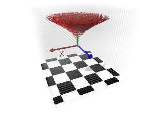
So here's what that looks like so far.
A better set of Falloff equations would be a useful toolkit for people to play
around more with this.
I think if I do 2 (4?) more isosurfaces with the .green and .blue components,
and a rgbf pigment, then maybe I can closely model the full-color pattern in 3D.
Or just do it in media with density patterns.
Anyway here's leopard scale 0.05 in a 4-unit cube with the twist effect in red. net> wrote:
> I'm going to try to apply a falloff from 1 to 0 in the y direction, and see if I
> can't code up an isosurface scene that works with that...
Right-o.
So I got the isosurface working with a pigment function, after Mike Williams'
invaluable site gave me the crucial function {} - 0.5 trick.
Then once I got the isosurface to display what was actually going on in 3D, I
realized that there was some rewriting needing to be done. The quicky function
that I piggybacked onto BP's code resulted in a plane at y=0 that looked great,
but as my earlier attempts at displaying the 25 different patterns suggested,
and the isosurface confirmed, all was not well at y != 0.
The distance function was spherical, and IIRC, I had changed the rotated pattern
to cylindrical (y=0). That resulted in a weird sphere of rotated pattern inside
an empty cylinder, surrounded by the default pattern.
So I fixed all of that, and then had to limit the rotation to only take place in
the 0 < y < 1 region. That made my head hurt for most of the morning. Got
that straightened out, and then generalized it to 0 < y < Radius.
So then had to concoct some sort of way to take that little cylinder of space
and taper it so that it was full radius at y=1, and 0 radius at y = 0.
So I nested another select function inside the first, and used that to control
where there was twist, and where there wasn't. After 6 or 8 petit mal
mathematical epileptic fits, and a trip to the laundromat (where I worked it out
in one last attempt) I got a usable equation for proof of concept.
Replacing Pattern(x,y,z).x with 0 gives me empty space where there is no twist,
thus having the isosurface model only the region where the effect is applied.
Then I reversed the outcomes to model only the default pattern with the affected
region missing, and gave that a mostly transparent pigment.
So here's what that looks like so far.
A better set of Falloff equations would be a useful toolkit for people to play
around more with this.
I think if I do 2 (4?) more isosurfaces with the .green and .blue components,
and a rgbf pigment, then maybe I can closely model the full-color pattern in 3D.
Or just do it in media with density patterns.
Anyway here's leopard scale 0.05 in a 4-unit cube with the twist effect in red.
Post a reply to this message
Attachments:
Download 'documentationfigures.png' (441 KB)
Preview of image 'documentationfigures.png'
|
|


