|
|
|
|
|
|
| |
| |
|
|
|
|
| |
| |
|
|
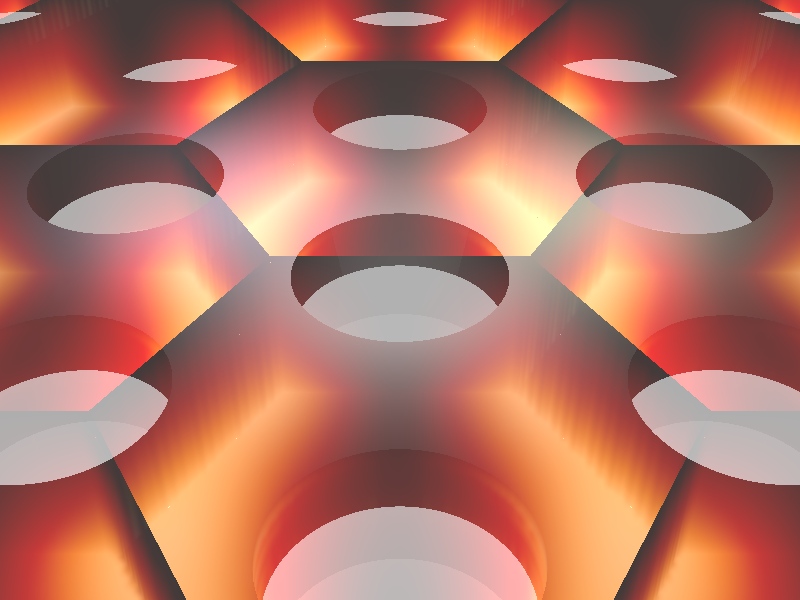
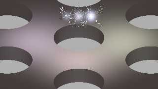
.... here is the render with patterning showing the overlap problem ...
Post a reply to this message
Attachments:
Download 'phc_and_excitation_enhancement.png' (254 KB)
Preview of image 'phc_and_excitation_enhancement.png'
|
|
| |
| |
|
|
|
|
| |
| |
|
|
.... and here is a zip with the scene again and the df3 files.
Post a reply to this message
Attachments:
Download 'pov_scene_and_df3s.zip' (212 KB)
|
|
| |
| |
|
|
|
|
| |
| |
|
|
"cbpypov" <nomail@nomail> wrote:
> I further set the QD absorption to 0. as Bald Eagle suggested. I really like the
> arrow thing you posted, but somehow I could not figure out where the `Vector`
> function comes from? My povray does not know it and I could not find an .inc
> that defines it. Could you post more code that you used for the image with
> arrows?
That's from Friedrich Lohmueller's analytical_g.inc file, which I _think_ comes
with POV-Ray.
http://www.f-lohmueller.de/pov_tut/addon/00_Basic_Templates/85_Analytical_Geo/__index.htm
> In the next to posts I will attach an image of the _patterned_ version, which is
> not working yet because the boxes in which the field is defined overlap. How can
> I solve this problem?
difference {} away the parts that overlap?
Post a reply to this message
|
|
| |
| |
|
|
|
|
| |
| |
|
|
I had that as part of a mental list to post, but it slipped off...
I was also thinking that if you wanted to represent an emission, you ought to
use the standard lambda-photon-sine-wave thing
like
https://physics.aps.org/assets/5f985b1a-28d8-4cb1-89f1-1ae7dedeac6f/e135_2_thumb.png
Just define it as an object that you can replace that quickie Vector () with.
And now I'm off to lunch.
Post a reply to this message
|
|
| |
| |
|
|
|
|
| |
| |
|
|
"Bald Eagle" <cre### [at] netscape net> wrote:
> I had that as part of a mental list to post, but it slipped off...
>
> I was also thinking that if you wanted to represent an emission, you ought to
> use the standard lambda-photon-sine-wave thing
>
> like
> https://physics.aps.org/assets/5f985b1a-28d8-4cb1-89f1-1ae7dedeac6f/e135_2_thumb.png
>
> Just define it as an object that you can replace that quickie Vector () with.
>
> And now I'm off to lunch.
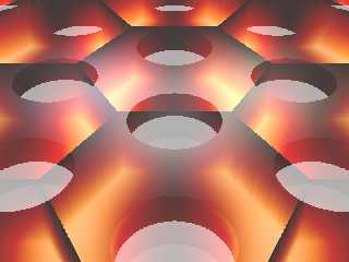
So for the fast case I managed to get rid of the overlap by defining the field
directly in a prism that I scale to the unit cell size, like this
#declare Field_object = prism {
linear_sweep
linear_spline
0., // sweep the following shape from here ...
1., // ... up through here
7, // the number of points making up the shape ...
<0.,0.5>, <0.25,1.>, <0.75,1.>, <1.,0.5>, <0.75,0.>, <0.25,0.>, <0.,0.5>
texture {
finish { diffuse 0 ambient 0 reflection 0 }
pigment {
colour rgbft <1.000,1.000,1.00,0.000,1.000>
}
}
hollow
interior{
ior 1.000
caustics 0.000
dispersion 1.000
dispersion_samples 7.000
fade_power 0.000
fade_distance 0.000
fade_color rgb <0.000,0.000,0.000>
// Red
media {
method 3
intervals 10
samples 1, 1
confidence 0.900
variance 0.008
ratio 0.900
absorption rgb <0,0,0>
emission rgb <1,0,0> * Field_brightness
aa_threshold 0.050
aa_level 4
density {
density_file df3 "efield_energy_in_superspace_R.df3"
interpolate Field_interpolation
}
}
// Green
media {
method 3
intervals 10
samples 1, 1
confidence 0.900
variance 0.008
ratio 0.900
absorption rgb <0,0,0>
emission rgb <0,1,0> * Field_brightness
aa_threshold 0.050
aa_level 4
density {
density_file df3 "efield_energy_in_superspace_G.df3"
interpolate Field_interpolation
}
}
// Blue
media {
method 3
intervals 10
samples 1, 1
confidence 0.900
variance 0.008
ratio 0.900
absorption rgb <0,0,0>
emission rgb <0,0,1> * Field_brightness
aa_threshold 0.050
aa_level 4
density {
density_file df3 "efield_energy_in_superspace_B.df3"
interpolate Field_interpolation
}
}
media {
absorption 0.
}
}
// Set proper size and position
scale field_box_dim
translate field_box_trans
}
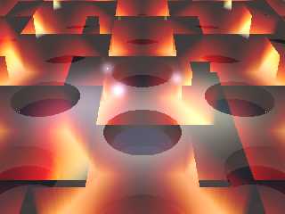
But still a problem is that the "black" parts of the color map are not
transparent (maybe because the density is not exactly 0.0?). So there is a kind
of "box" still visible, which destroys the complete image. See the attachment.
Help! :)
For the emitter thing: yes that "standard lambda-photon-sine-wave thing" would
really be a great thing to have ... er ... how do I do that? :) net> wrote:
> I had that as part of a mental list to post, but it slipped off...
>
> I was also thinking that if you wanted to represent an emission, you ought to
> use the standard lambda-photon-sine-wave thing
>
> like
> https://physics.aps.org/assets/5f985b1a-28d8-4cb1-89f1-1ae7dedeac6f/e135_2_thumb.png
>
> Just define it as an object that you can replace that quickie Vector () with.
>
> And now I'm off to lunch.
So for the fast case I managed to get rid of the overlap by defining the field
directly in a prism that I scale to the unit cell size, like this
#declare Field_object = prism {
linear_sweep
linear_spline
0., // sweep the following shape from here ...
1., // ... up through here
7, // the number of points making up the shape ...
<0.,0.5>, <0.25,1.>, <0.75,1.>, <1.,0.5>, <0.75,0.>, <0.25,0.>, <0.,0.5>
texture {
finish { diffuse 0 ambient 0 reflection 0 }
pigment {
colour rgbft <1.000,1.000,1.00,0.000,1.000>
}
}
hollow
interior{
ior 1.000
caustics 0.000
dispersion 1.000
dispersion_samples 7.000
fade_power 0.000
fade_distance 0.000
fade_color rgb <0.000,0.000,0.000>
// Red
media {
method 3
intervals 10
samples 1, 1
confidence 0.900
variance 0.008
ratio 0.900
absorption rgb <0,0,0>
emission rgb <1,0,0> * Field_brightness
aa_threshold 0.050
aa_level 4
density {
density_file df3 "efield_energy_in_superspace_R.df3"
interpolate Field_interpolation
}
}
// Green
media {
method 3
intervals 10
samples 1, 1
confidence 0.900
variance 0.008
ratio 0.900
absorption rgb <0,0,0>
emission rgb <0,1,0> * Field_brightness
aa_threshold 0.050
aa_level 4
density {
density_file df3 "efield_energy_in_superspace_G.df3"
interpolate Field_interpolation
}
}
// Blue
media {
method 3
intervals 10
samples 1, 1
confidence 0.900
variance 0.008
ratio 0.900
absorption rgb <0,0,0>
emission rgb <0,0,1> * Field_brightness
aa_threshold 0.050
aa_level 4
density {
density_file df3 "efield_energy_in_superspace_B.df3"
interpolate Field_interpolation
}
}
media {
absorption 0.
}
}
// Set proper size and position
scale field_box_dim
translate field_box_trans
}
But still a problem is that the "black" parts of the color map are not
transparent (maybe because the density is not exactly 0.0?). So there is a kind
of "box" still visible, which destroys the complete image. See the attachment.
Help! :)
For the emitter thing: yes that "standard lambda-photon-sine-wave thing" would
really be a great thing to have ... er ... how do I do that? :)
Post a reply to this message
Attachments:
Download 'phc_and_excitation_enhancement.png' (250 KB)
Preview of image 'phc_and_excitation_enhancement.png'
|
|
| |
| |
|
|
|
|
| |
| |
|
|
"cbpypov" <nomail@nomail> wrote:
> But still a problem is that the "black" parts of the color map are not
> transparent (maybe because the density is not exactly 0.0?). So there is a kind
> of "box" still visible, which destroys the complete image. See the attachment.
> Help! :)
Maybe there needs to be a t in one of your rgb statements?
I'll have to look at it when I get back home.
> For the emitter thing: yes that "standard lambda-photon-sine-wave thing" would
> really be a great thing to have ... er ... how do I do that? :)
plot spheres:
http://www.f-lohmueller.de/pov_tut/calc/math_500e.htm
http://news.povray.org/povray.binaries.images/thread/%3Cweb.5926c5ddec053131c437ac910%40news.povray.org%3E/
http://news.povray.org/povray.binaries.images/thread/%3Cweb.58b813187922eedfc437ac910%40news.povray.org%3E/
http://news.povray.org/povray.binaries.images/thread/%3Cweb.5781842fa68f756e5e7df57c0@news.povray.org%3E/
Use a sphere sweep
http://www.povray.org/documentation/view/3.7.1/63/
(instead of points, do a loop with a function evaluating the sine of current
counter value)
parametric isosurface using spline
http://www.econym.demon.co.uk/isotut/more.htm
http://www.econym.demon.co.uk/isotut/splines.htm
I'm sure there may be other clever ways, but fast and simple is usually best.
If you want arrowheads, just define a vector by subtracting the penultimate
sphere from the last sphere to give you a direction, and then start a cone{} at
the last sphere and end at a multiple of that vector.
[That ought to be the correct way to do it...]
Though the arrow out to be pointing straight out...
Post a reply to this message
|
|
| |
| |
|
|
|
|
| |
| |
|
|
Oh, and I found a link to an Angewandte Chemie cover done with POV-Ray that uses
code to make a spring:
http://www.somewhereville.com/?cat=1136
:)
Post a reply to this message
|
|
| |
| |
|
|
|
|
| |
| |
|
|
"Bald Eagle" <cre### [at] netscapenet> wrote:
> Oh, and I found a link to an Angewandte Chemie cover done with POV-Ray that uses
> code to make a spring:
>
> http://www.somewhereville.com/?cat=1136
>
> :)
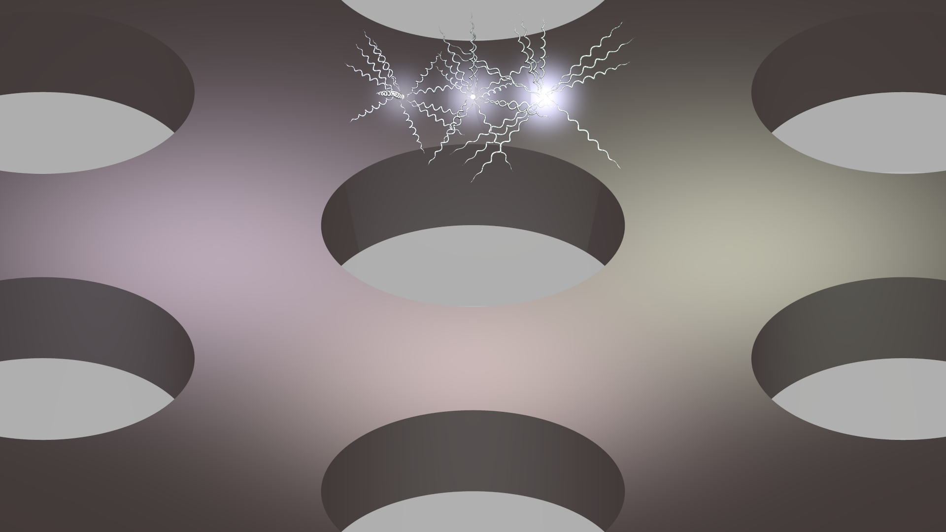
Hey, the spiral thing is really nice. I played around with it, the the result
attached (I added a sin() in the x-displacment of the spheres). But it is
getting rather confusing now :) Maybe I'll stick to the glowing...
Important: could you please post the code you used for the emitters that you
used? I still have the overlap problem, although I set absorption to 0. Since it
is working for you, it will be nice to have the code. Maybe this can also be
applied to field overlap problem...
Where could I integrate a transmittance in the code that uses 3 different media
for RGB (based in Stephen's snippet)? Should there be some kind of colormap?
An new question: how can I achieve a "corner rounding" for the hole? I tried to
subtract an hourglass-like `sor`, but without success :(
Post a reply to this message
Attachments:
Download 'phc_and_excitation_enhancement.png' (453 KB)
Preview of image 'phc_and_excitation_enhancement.png'
|
|
| |
| |
|
|
|
|
| |
| |
|
|
"cbpypov" <nomail@nomail> wrote:
> Hey, the spiral thing is really nice. I played around with it, the the result
> attached (I added a sin() in the x-displacment of the spheres). But it is
> getting rather confusing now :) Maybe I'll stick to the glowing...
#version 3.71;
global_settings {
assumed_gamma 1.0
}
#declare Aspect = image_width/image_height;
camera {
location <0.5, 0, -5>
right x*Aspect
look_at <0, 0, 0>
}
#include "colors.inc"
#declare A = 0.1;
#declare R = 0.01;
#declare Freq = 10;
#declare Photon = union {
#for (X, 0, tau, 0.01)
// plot function
#declare Y = A*sin(Freq*X);
sphere {<X/tau, Y, 0> R}
#end
cylinder {0, <X/tau, Y, 0> R pigment {Red}}
cone {<X/tau, Y, 0>, R*3, <(X/tau)*1.1, Y, 0>, 0 pigment {Red}}
pigment {Yellow}
}
object {Photon}
> Important: could you please post the code you used for the emitters that you
> used? I still have the overlap problem, although I set absorption to 0. Since it
> is working for you, it will be nice to have the code. Maybe this can also be
> applied to field overlap problem...
//##########################################################
#declare Exp_decay = function {
exp( -(pow(x,2) + pow(y,2) + pow(z,2))*80. )
};
#macro QuantumDot(Radius, Radius_aura, Intensity, Origin)
// The actual quantum dot
sphere{
<0,0,0>, Radius
texture{ Glass2 } // end of texture
translate Origin
} // end of sphere
// The glowing aura
sphere {
<0,0,0>,
Radius_aura*(1+Intensity)
pigment { rgbt 1 } hollow
interior
{ media
{ emission Intensity*5
density {
function { Exp_decay(x,y,z) }
color_map {
[0.0 rgbt <0,0,0,1>]
[0.5 rgbt <0.5, 0.5, 0.7,1>]
[1.0 rgbt <1,1,1,1>]
}
}
}
media
{ absorption 0
}
}
translate Origin
}
// #end // end of #for loop
#end // ------------------ end of macro
//##########################################################
> Where could I integrate a transmittance in the code that uses 3 different media
> for RGB (based in Stephen's snippet)? Should there be some kind of colormap?
you have rgb for absorption and transmission - try rgbt.
Also - since you're juxtaposing all those shapes, it may the coincident / near
coincident surface problem.
You may want to do the object as a plane or box with holes, or a hexagonal
pigment pattern instead. You can _really_ fake 3D CSG with well-chosen and
applied pigments and textures.
https://mscharrer.net/povray/bridge/
> An new question: how can I achieve a "corner rounding" for the hole? I tried to
> subtract an hourglass-like `sor`, but without success :(
Step-by-step instructions: :)
http://www.f-lohmueller.de/pov_tut/backgrnd/p_wat4.htm
Post a reply to this message
|
|
| |
| |
|
|
From: Alain
Subject: Re: Example images for the related post: "Rendering an electromagnetic fiel=
Date: 27 Oct 2017 21:02:57
Message: <59f3d741@news.povray.org>
|
|
|
| |
| |
|
|
> "Bald Eagle" <cre### [at] netscapenet> wrote:
>>
>> It seems the thing to do is model the hexagonal unit cell, union it as an
>> all-inclusive object, and then repeat it in a hexagonal arrangement.
>>
>> I'm also thinking that you probably don't even need to go the df3 file route,
>> since you're already calculating your field. You can just use that function to
>> _directly_ define the density of your media.
>> Likewise, you can use that function to map your colors, and according to the
>> Bourke site,
>> "The POVRay file is here: example.pov, note that the density in this example
>> just controls the emission in the media."
>> - so the emission brightness can be controlled that way as well.
>> Just normalize your function so all values are within the 0-1 range.
>>
>> Hit F1 and type density
>> then go to the density, media section:
>>
>> 3.7.2.4 Density
>>
>> "The density statement may begin with an optional density identifier. All
>> subsequent values modify the defaults or the values in the identifier. The next
>> item is a pattern type. This is any one of POV-Ray's pattern functions such as
>> bozo, wood, gradient, waves, etc. Of particular usefulness are the spherical,
>> planar, cylindrical, and boxed patterns which were previously available only for
>> use with our discontinued halo feature. All patterns return a value from 0.0 to
>> 1.0. This value is interpreted as the density of the media at that particular
>> point."
>
>
> What you write sounds extremely reasonable to me! I am right now generating the
> field data (sorry for the delay, the hard drive of my PC at work crashed
> completely ... 1 month before the end of my PhD phase). So I will try to figure
> out the density mapping post my results later.
>
> Until then, could someone of you have a look on the things that I tried related
> to the emitters: I basically created this macro to generated small spheres with
> a glowing "aura":
>
> #macro QuantumDot(Radius, Intensity, Origin)
>
> // The actual quantum dot
> sphere{
> <0,0,0>, Radius
> texture{ Glass2 } // end of texture
> translate Origin
> } // end of sphere
>
> // The glowing aura
> sphere {
> <0,0,0>,
> Radius* (Intensity*5 + 1)
> pigment { rgbt 1 } hollow
> interior
> { media
> { emission Intensity
> density { spherical
> color_map {
> [0.0 rgb <0,0,0>]
> [0.6 rgb <0., 0., 0>]
> [0.7 rgb <0.6, 0.6, 0.6>]
> [1.0 rgb <1,1,1>]
> }
> }
> }
> }
> translate Origin
> }
> // #end // end of #for loop
>
> #end // ------------------ end of macro
>
>
> Although it looks quite nice to me, there is the problem that the emitting
> spheres do not "overlap" properly (I'd expect that the intensity of the emission
> would add up!?). Moreover, I would want a smooth fade-out of the aura, but yet
> it is dependent on the intensity: with Intensity=1 it looks fine, while
> Intensity=0.4 rather looks like an additional sphere. Please see the attachment.
>
> Any comments greatly appreciated :)
>
The media container on the right never overlap the other two, while
there is a visual overlap on the left, and maybe also a physical
overlap. Those overlaping part are known to cause that kind of problems.
You should use a single container. When you have multiple medias within
a single container, they add up.
Multiple densities within the same media will multiply instead.
So, you should place the small spheres, then fill a box with your medias.
You may need to increase the number of samples.
The render time will increase as the number of medias increase.
Post a reply to this message
|
|
| |
| |
|
|
|
|
| |
|
|