|
 |
On 05/03/2016 08:44 AM, clipka wrote:
> Am 03.05.2016 um 14:22 schrieb William F Pokorny:
>
>> I have captured the code you posted to github as another test. It
>> renders OK in the copy of code where I turned off the current checking.
>
> Does it also compute the surface orientation properly?
>
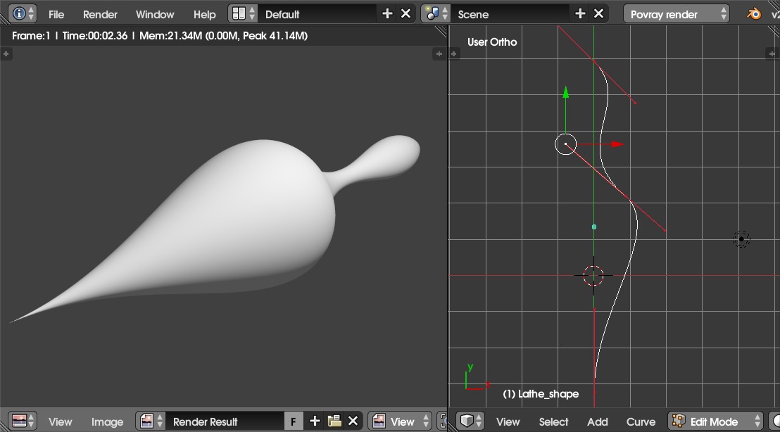
Well got hung up for the morning when LanuHum's shape rendered initially
inside out.
Finally ran it down to the fact the ordering of the points in Y flips
the surface normal of lathes - behavior which is news to me. This is an
issue apart from any others we have running in this thread.
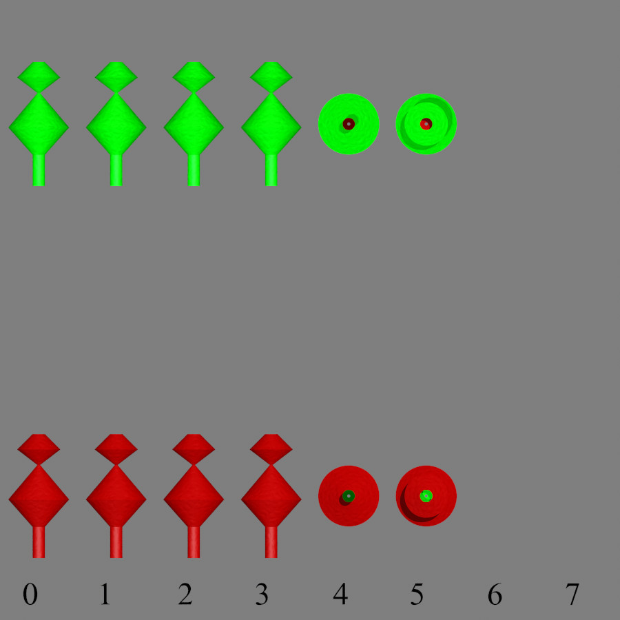
I created a version of LanuHum's point set where I shifted all X
coordinates positive. In the attached image the top row is this point
list, which starts at the top and moves downward, used in a
linear_spline. The green result is the inside texture. The columns are
various rotations of the base lathe.
The row at the bottom is the same point set, but with the points
re-ordered in the linear_spline specification so the Y coordinate's
start at the bottom and move upward. We now get shapes which have the
correct normals.
The lathe of course can have folds - a class of tangled curves we've
ignored in this discussion thus far - so we cannot just sort by y
coordinate to normalize the normals so to speak. I am unsure at the
moment what happens with the normals in Y folds as I've not tried it.
And down the rabbit hole we go. :-)
Will probably be tomorrow before I get back to looking at the original
questions.
Bill P.
Post a reply to this message
Attachments:
Download 'y_orderingflipslathenormal.jpg' (61 KB)
Preview of image 'y_orderingflipslathenormal.jpg'
|
|
|
|
On 05/03/2016 01:02 PM, clipka wrote:
> Am 03.05.2016 um 18:32 schrieb William F Pokorny:
>
>> And down the rabbit hole we go. :-)
>
> See what I meant when I said I wouldn't have the time right now? ;)
>
Certainly beginning to get the picture! Guess I'm still trying to figure
out whether there is some tactical, near term parser checking changes
that could be made to make the lathe more friendly to users.
To that end I have been working on test cases. I'm not done and work
will slow as I have family in town for a long weekend starting later today.
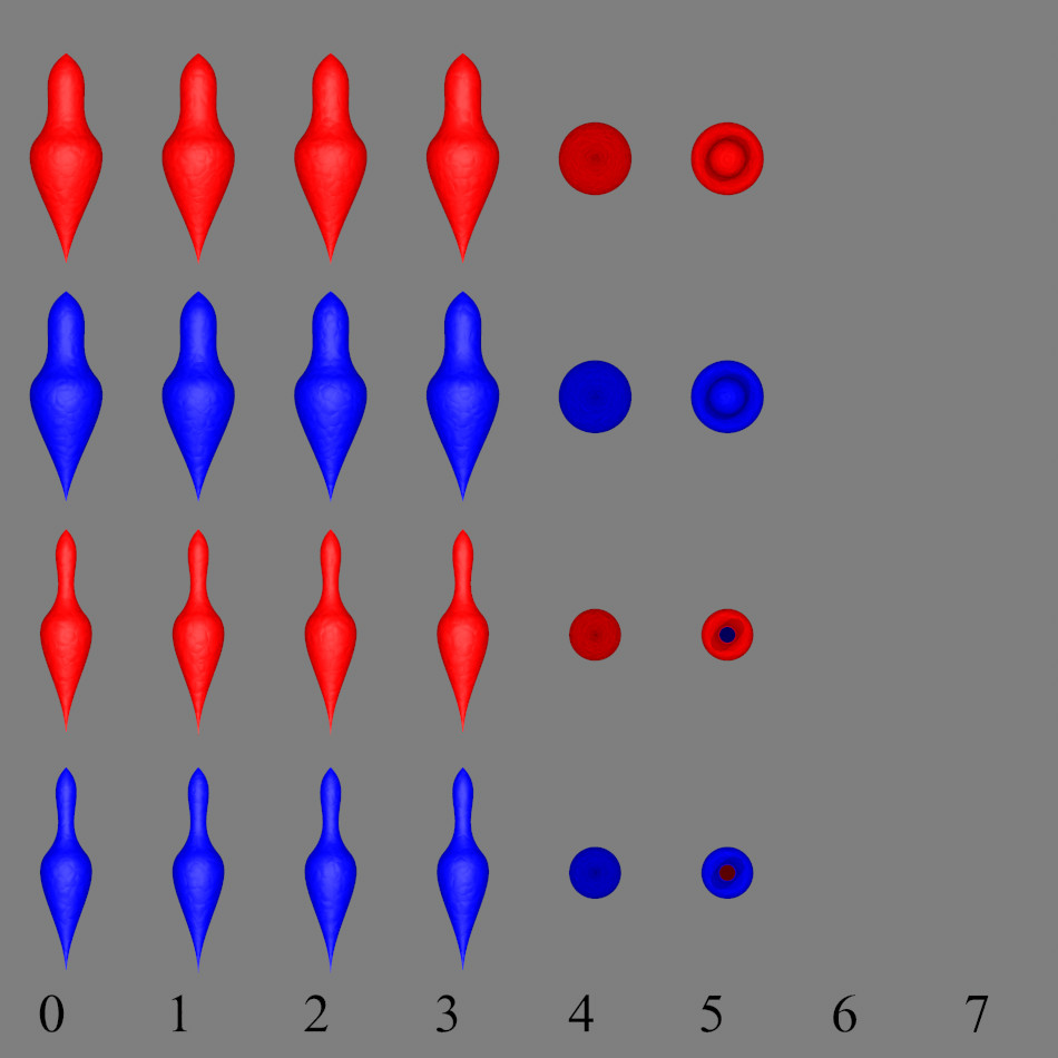
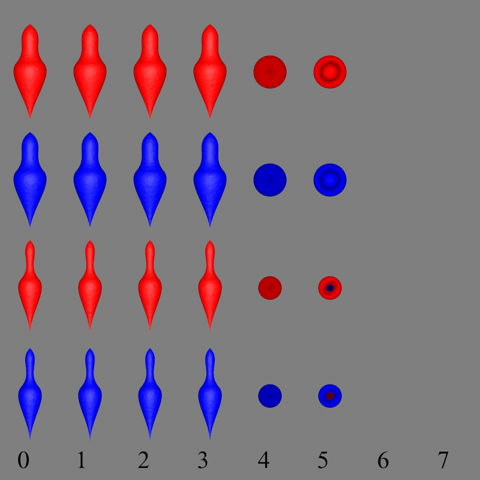
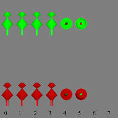
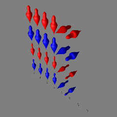
However, I'll to post a couple images in response to your question about
Lanuhum's lathe in particular. Here the blue are inside out and
correspond to LanuHum's original ordering. The red have been flipped in
order to the bezier spline.
The two rows at top have been modified so there are no negative
coordinates in x but the shape still closes to x==0 at top and bottom.
The bottom to rows are the original points.
So! Depending on the angle of the ray relative to the lathe, it looks
like the x<0 control point does indeed sometimes cause a flip in normals
at one end.
In other news the ordering of X as in Y can also flip normals - suppose
expected mostly.
Bill P.
Post a reply to this message
Attachments:
Download 'setlanuhum_orthographic.jpg' (85 KB)
Download 'setlanuhum_orthographic.png' (456 KB)
Preview of image 'setlanuhum_orthographic.jpg'
Preview of image 'setlanuhum_orthographic.png'
|
|
|
|
On 05/04/2016 12:09 PM, William F Pokorny wrote:
> On 05/03/2016 01:02 PM, clipka wrote:
>> Am 03.05.2016 um 18:32 schrieb William F Pokorny:
>>
>>> And down the rabbit hole we go. :-)
>>
>> See what I meant when I said I wouldn't have the time right now? ;)
>>
>
> Certainly beginning to get the picture! Guess I'm still trying to figure
> out whether there is some tactical, near term parser checking changes
> that could be made to make the lathe more friendly to users.
>
> To that end I have been working on test cases. I'm not done and work
> will slow as I have family in town for a long weekend starting later today.
>
> However, I'll to post a couple images in response to your question about
> Lanuhum's lathe in particular. Here the blue are inside out and
> correspond to LanuHum's original ordering. The red have been flipped in
> order to the bezier spline.
>
> The two rows at top have been modified so there are no negative
> coordinates in x but the shape still closes to x==0 at top and bottom.
> The bottom to rows are the original points.
>
> So! Depending on the angle of the ray relative to the lathe, it looks
> like the x<0 control point does indeed sometimes cause a flip in normals
> at one end.
>
> In other news the ordering of X as in Y can also flip normals - suppose
> expected mostly.
>
> Bill P.
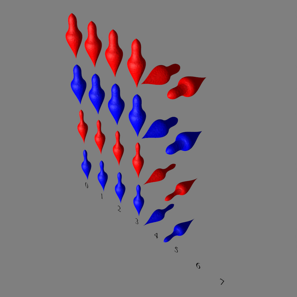
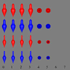
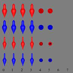
Yep & sorry all. In rushing I posted two formats of the same image...
Perspective jpg attached.
Bill P.
Post a reply to this message
Attachments:
Download 'setlanuhum_perspective.jpg' (69 KB)
Preview of image 'setlanuhum_perspective.jpg'
|
|
|
|
On 05/02/2016 03:16 PM, clipka wrote:
> Am 02.05.2016 um 19:47 schrieb William F Pokorny:
>
>> I think I covered all the cases somewhat, but if not let me know.
>
> What about these:
>
> - first and third point negative
>
> - second and fourth point negative
>
> - first and fourth point negative
>
> Also, so far you've only swapped the signs; what if the negative values
> have greater magnitude than the positive ones? What about quadratic
> splines with an odd number of control points?
>
> There's plenty more stuff to toy around with.
>
> I also think it would be worthwhile to examine what happens if the lathe
> has an interior_texture.
>
>
>> To my eyes we get what one might expect(1) with negative coordinates, so
>> running with better warnings or no checking at all of the points in the
>> spline is probably OK.
>
> I'm not happy at all with the following cases:
>
> - the entire column 1 (all-negative); technically these should look the
> same as column 0, shouldn't they?
>
> - the cubic spline column 6; we should see /something/ there
>
> - the quadratic spline columns 6 and 7; we do see from the shading that
> they are bulging, but the silhouettes are cylindrical in the
> orthographic view, and the shapes look cut off in the perspective view.
>
> My suspicion is that the internal bounding mechanism of the late
> primitive doesn't play nice with negative values, which would explain
> all the above oddities.
>
>
> Furthermore, columns 5 and 7 should look identical in all respects for
> all splines, but instead we consistently see notable differences in the
> shading (and maybe also self-shadowing, but that's not entirely clear).
> This indicates to me that the normal computations are thrown off the
> rails by negative values as well.
>
>
> This means you(!) now have a choice to make:
>
> (A) Just overhaul the error message check.
>
> (B) Fix the lathe primitive itself, by making the bounding mechanism
> properly deal with negative values (this should be reasonably easy) and
> making the normal computations properly deal with "flipped" portions
> (this might be more difficult).
>
> (C) Work around the lathe primitive's limitations at the parser level,
> by automatically splitting any non-conforming sections into two or three
> sub-sections, inserting additional control points along the way, and
> normalizing the "flipped" portions by just inverting the sign. (This
> should be trivial for linear splines, some work for bezier splines, but
> may turn out to be difficult or even impossible for quadratic and cubic
> splines.)
>
> (D) Just like (C), but make the corresponding code part of the lathe
> primitive itself by placing it inside the Lathe::Compute_Lathe() method.
>
>
> Any of the above solutions would be accepted (presuming the resulting
> implementation is of reasonable quality of course).
>
>
> One final note in case you go for (A): In addition to the error messages
> for negative on-curve control points I'd also like to see warnings for
> negative off-curve bezier control points, as such points may or may not
> lead to "flipped" portions and the normal computation for such portions
> demonstrably cannot be trusted at present. Of course it would also be
> neat if the parser could automatically detect whether a lathe object
> will actually have "flipped" portions (not only for bezier but also for
> quadratic and cubic splines, which can "overshoot" even with
> all-positive control points) but that's probably beyond the scope of
> parse-time parameter sanity checks.
>
>
>> (1)- except perhaps that quadratic is a bit noisy, but probably it is
>> not much used.
>
> Try "sturm", that should give smoother results.
>
The short of it after creating and running a large number of test cases
is to go with your option (A) also adding in the negative control point
warning for the bezier spline versions of the lathe. I'll work to get a
pull request going and I'll create a tarball for all the test cases
which I'll post to:
https://github.com/POV-Ray/povray/issues/60
I think, Christoph, your guesses as to behavior and the reasons for them
in what I previously posted were pretty much on track. I see no
compelling reason to permit negative - in x - on curve points in the lathe.
In summary, current on curve point checking for positive x is correct
only for the cubic spline, wrong for the bezier control points and both
its ends, and wrong for one or both ends of the quadratic and linear
splines, respectively. The new checking forces all on curve, specified
points, to be positive in x. Know that while not too likely, somebody,
somewhere, no doubt specified point(s) which worked with the previous
code which will now need adjustment at the first, last point or both.
Other discoveries, odds and ends.
a) It is possible with point sets where x is always positive to create
twisted, overlapping shapes which confuse or flip normal determination.
I suspect we'd need to check for self crossing, as evaluated, spline
paths to fully prevent this.
b) It is possible with point sets where x is always positive to create
splines with portions in -x not properly bounded or rendered with
Quadratic and Cubic splines. Aside from the linear spline, we would need
to reasonably evaluate the spline's path when setting the bbox to
prevent this.
c) Looked too at the prism's use of splines and there too, as with
lathes, the ordering of the point sets can flip the overall normals -
for the prism's sides. An interesting sub-note here is that for some
reason the prism-side's normal for the bezier splines are backwards from
the other three spline types. The top and bottom of prism objects always
face outward from the closed portions.
d) A neat surprise to me is the bezier spline in the lathe specification
can have disjoint subsections. See Set10_*.pov in the test cases. This
kind of thing can be be done for all spline types as used in prisms. It
also makes the ability to flip the normals, inside/outside according to
point set direction somewhat useful in that more complex, two-textured,
lathes can be created within one lathe-spline definition.
e) Due (c) & (d) I'd recommend leaving behavior as is for now and
updating the documentation to make clear the spline point order has an
effect of lathe and prism normals and differing inside and outside
textures should be used if one needs to be sure how their shape is being
interpreted.
f) I looked a little at the surface of revolution (SOR) object and it
allows negative coordinates in x with a disclaimer, but enforces a rigid
direction and ordering in Y.
g) There is a text file describing the rows and columns for each
test-case set and for the sets 1-6 the parser checking would need to be
suppressed to see a result.
Bill P.
Post a reply to this message
|
|
|
|
Am 14.05.2016 um 13:56 schrieb William F Pokorny:
> c) Looked too at the prism's use of splines and there too, as with
> lathes, the ordering of the point sets can flip the overall normals -
> for the prism's sides. An interesting sub-note here is that for some
> reason the prism-side's normal for the bezier splines are backwards from
> the other three spline types. The top and bottom of prism objects always
> face outward from the closed portions.
Can you distill this into a GitHub issue? I don't think this is how
things should be, but I currently don't have time to address it.
Thanks a lot for your quite exhaustive analysis!
> e) Due (c) & (d) I'd recommend leaving behavior as is for now and
> updating the documentation to make clear the spline point order has an
> effect of lathe and prism normals and differing inside and outside
> textures should be used if one needs to be sure how their shape is being
> interpreted.
If you want to go the extra mile, you could write up a suggested change
to the Docs as maintained on the Wiki (http://wiki.povray.org).
> f) I looked a little at the surface of revolution (SOR) object and it
> allows negative coordinates in x with a disclaimer, but enforces a rigid
> direction and ordering in Y.
Yes, that rigid Y ordering is the primary limitation of the SOR object
(I presume it predates the lathe).
Post a reply to this message
|
|