|
 |
"Halbert" <hal### [at] gmail com> wrote:
> I would be interested to know how the sides were accomplished with the
> overlapping boards. Very nice so far!
>
> --
Hi Halbert,
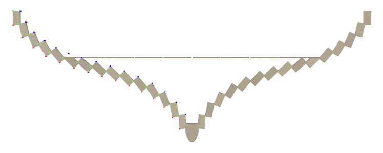
This cross section will help show how the boards (called strakes) overlap.
The colored dots in the picture are markers to help me write to code. The
red dots represent a starting location for each strake. The green dots
represent a target location where that strake should end, after being
rotated a specified amount. The starting location for the next strake can
then be computed based on where the previous one ended. The strakes are
created from the bottom upward. The original start and target locations are
saved in arrays for future use.
The actual ship is made of hundreds of cross section segments individually
sized.
This method of construction has several advantages: First, I wanted to be
able to make the hull narrower at the ends without changing the thickness
of the sides. Simply using the "scale" command on the hull would have also
made the walls of the ship thinner. By changing the start and target
locations of the strakes, the hull can be narrowed without changing the
thickness of the strakes.
Second, POV can do most of the work in creating the profile of the hull. All
I had to do was make a table of angles to rotate each strake. I can
experiment with the angles easily and POV will adjust the positions of all
the strakes for me.
Here's the code to make the hull cross section: (The ".9" factor controls
how far the strakes overlap.)
#macro DefineHullProfile (StrakeThickness, KeelWidth, KeelHeight)
#declare MasterTargetLocation = array [15]
#declare MasterStartLocation = array [15]
#local StrakeWidth = .14;
#declare StrakeAngle = array [15] {
4, // 0
11, // 1
22, // 2
31, // 3
39, // 4
42, // 5
45, // 6
47, // 7
48, // 8
45, // 9
39, // 10
31, // 11
22, // 12
12, // 13
-.4 // 14
} //array
#local CurX = -KeelWidth / 2;
#local CurY = KeelHeight - .04;
#local I = 0;
#while (I < 15)
#local CurX = CurX - StrakeThickness * cos (radians (StrakeAngle
[I]));
#local CurY = CurY - StrakeThickness * sin (radians (StrakeAngle
[I]));
#declare MasterStartLocation [I] = <CurX, CurY, 0>;
#local TargetX = CurX - StrakeWidth * cos (radians (-90 + StrakeAngle
[I]));
#local TargetY = CurY - StrakeWidth * sin (radians (-90 + StrakeAngle
[I]));
#declare MasterTargetLocation [I] = <TargetX, TargetY, 0>;
#local CurX = CurX - StrakeWidth * .9 * cos (radians (-90 +
StrakeAngle [I]));
#local CurY = CurY - StrakeWidth * .9 * sin (radians (-90 +
StrakeAngle [I]));
#local I = I + 1;
#end //#while
#declare MasterYOffset = MasterTargetLocation [14].y;
#end //#macro DefineHullProfile com> wrote:
> I would be interested to know how the sides were accomplished with the
> overlapping boards. Very nice so far!
>
> --
Hi Halbert,
This cross section will help show how the boards (called strakes) overlap.
The colored dots in the picture are markers to help me write to code. The
red dots represent a starting location for each strake. The green dots
represent a target location where that strake should end, after being
rotated a specified amount. The starting location for the next strake can
then be computed based on where the previous one ended. The strakes are
created from the bottom upward. The original start and target locations are
saved in arrays for future use.
The actual ship is made of hundreds of cross section segments individually
sized.
This method of construction has several advantages: First, I wanted to be
able to make the hull narrower at the ends without changing the thickness
of the sides. Simply using the "scale" command on the hull would have also
made the walls of the ship thinner. By changing the start and target
locations of the strakes, the hull can be narrowed without changing the
thickness of the strakes.
Second, POV can do most of the work in creating the profile of the hull. All
I had to do was make a table of angles to rotate each strake. I can
experiment with the angles easily and POV will adjust the positions of all
the strakes for me.
Here's the code to make the hull cross section: (The ".9" factor controls
how far the strakes overlap.)
#macro DefineHullProfile (StrakeThickness, KeelWidth, KeelHeight)
#declare MasterTargetLocation = array [15]
#declare MasterStartLocation = array [15]
#local StrakeWidth = .14;
#declare StrakeAngle = array [15] {
4, // 0
11, // 1
22, // 2
31, // 3
39, // 4
42, // 5
45, // 6
47, // 7
48, // 8
45, // 9
39, // 10
31, // 11
22, // 12
12, // 13
-.4 // 14
} //array
#local CurX = -KeelWidth / 2;
#local CurY = KeelHeight - .04;
#local I = 0;
#while (I < 15)
#local CurX = CurX - StrakeThickness * cos (radians (StrakeAngle
[I]));
#local CurY = CurY - StrakeThickness * sin (radians (StrakeAngle
[I]));
#declare MasterStartLocation [I] = <CurX, CurY, 0>;
#local TargetX = CurX - StrakeWidth * cos (radians (-90 + StrakeAngle
[I]));
#local TargetY = CurY - StrakeWidth * sin (radians (-90 + StrakeAngle
[I]));
#declare MasterTargetLocation [I] = <TargetX, TargetY, 0>;
#local CurX = CurX - StrakeWidth * .9 * cos (radians (-90 +
StrakeAngle [I]));
#local CurY = CurY - StrakeWidth * .9 * sin (radians (-90 +
StrakeAngle [I]));
#local I = I + 1;
#end //#while
#declare MasterYOffset = MasterTargetLocation [14].y;
#end //#macro DefineHullProfile
Post a reply to this message
Attachments:
Download 'hullcrosssection.png' (22 KB)
Preview of image 'hullcrosssection.png'
|
|