|
|
|
|
|
|
| |
| |
|
|
|
|
| |
| |
|
|
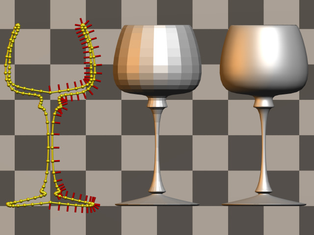
I was experimenting with a small macro which creates a mesh shaped like
a lathe from a spline. (The advantage of meshes over lathes is speed. Another
one is that with lathes you sometimes get artifacts which you don't get with
meshes.)
This should demonstrate what does the macro do:
----------8<------------8<-------------8<-------------8<-----------8<------
#macro MakeEvenSplinePoints(Points)
#local Amnt = dimension_size(Points, 1)-1;
#local Ind = 0;
#while(Ind <= Amnt)
Ind/Amnt, Points[Ind]
#local Ind = Ind+1;
#end
#end
#declare Points = array[18]
{ <0,.1>,<1,0>,<1.2,.05>,<1,.1>,<.2,.3>,
<.25,.4>,<.1,.9>,<.1,2.5>,<.3,2.8>,<.3,3.1>,
<1,3.25>,<1.25,4>,<1,5>,<.9,5>,<1.1,4.5>,
<1.15,3.8>,<1,3.4>,<0,3.2>
}
#declare Spline = spline { cubic_spline MakeEvenSplinePoints(Points) }
camera { location -z*14 look_at 0 angle 35 orthographic translate y*2.5 }
light_source { <100,200,-300>, 1 }
light_source { <-100,20,-30>, <1,.5,0>*.5 }
plane { -z,0 pigment { checker rgb 1, rgb .5 } }
// Final mesh:
object
{ MeshLathe(Spline, 80, 20)
no_shadow
pigment { rgb 1 } finish { specular .5 }
translate x*3
}
// Mesh with flat triangles:
#declare MeshLatheDebug=3;
object
{ MeshLathe(Spline, 80, 20)
no_shadow
pigment { rgb 1 } finish { specular .5 }
}
// Spline preview with normals:
#declare MeshLatheDebug=2;
#declare MeshLatheDebugNormalColor=x;
object
{ MeshLathe(Spline, 80, 20)
no_shadow
pigment { rgb x+y } finish { specular .5 }
translate x*-3
}
----------8<------------8<-------------8<-------------8<-----------8<------
Post a reply to this message
Attachments:
Download 'MeshLatheDebug.jpg' (53 KB)
Download 'MeshLatheExample.jpg' (23 KB)
Preview of image 'MeshLatheDebug.jpg'
Preview of image 'MeshLatheExample.jpg'

|
|
| |
| |
|
|
|
|
| |
| |
|
|
Warp wrote:
>
> I was experimenting with a small macro which creates a mesh shaped like
> a lathe from a spline. (The advantage of meshes over lathes is speed. Another
> one is that with lathes you sometimes get artifacts which you don't get with
> meshes.)
>
Have you tried:
Subject: mesh creation macros
Date: 17 Nov 2001 08:36:51 -0500
From: ingo <ing### [at] home nl>
Newsgroups: povray.binaries.scene-files
Christoph
--
POV-Ray tutorials, IsoWood include,
TransSkin and more: http://www.tu-bs.de/~y0013390/
Last updated 21 Feb. 2002 _____./\/^>_*_<^\/\.______ nl>
Newsgroups: povray.binaries.scene-files
Christoph
--
POV-Ray tutorials, IsoWood include,
TransSkin and more: http://www.tu-bs.de/~y0013390/
Last updated 21 Feb. 2002 _____./\/^>_*_<^\/\.______
Post a reply to this message
|
|
| |
| |
|
|
|
|
| |
| |
|
|
"Warp" wrote:
> I was experimenting with a small macro which creates
> a mesh shaped like a lathe from a spline.
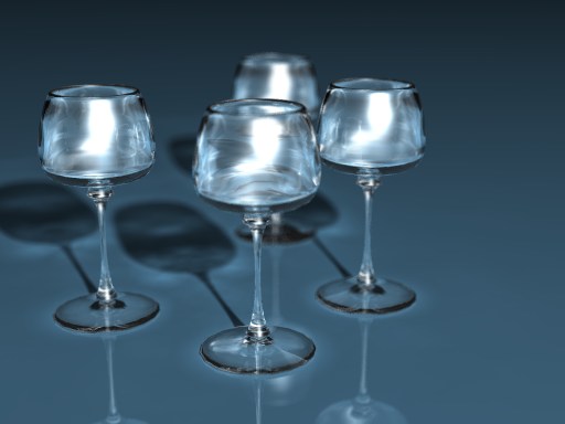
Ohh, that's very nice! The second image looks very realistic!
Have you found out what the speed increase is?
Also, have you compared the shape with a real lathe object using the same
control points? As the cubic spline used isn't the same, they might differ a
little. I also see that the two places where the spline meet the center axis
are not smooth, because the spline has not been closed properly. (Well, I
assume it was not intentional.) That's probably because it's not very easy
to close a natural cubic spline, which is the one currently used in the
spline feature, but not the one used in lathes.
Rune
--
3D images and anims, include files, tutorials and more:
Rune's World: http://rsj.mobilixnet.dk (updated Feb 16)
POV-Ray Users: http://rsj.mobilixnet.dk/povrayusers/
POV-Ray Webring: http://webring.povray.co.uk
Post a reply to this message
|
|
| |
| |
|
|
|
|
| |
| |
|
|
Rune <run### [at] mobilixnetdk> wrote:
> Ohh, that's very nice! The second image looks very realistic!
Thanks.
> Have you found out what the speed increase is?
I didn't test with that particular scene, but I tried putting 5 instances
of the object (with just a pigment { rgb 1 }) either as a true lathe or as a
mesh and the speed difference is very high. A test render (800x600 +a0.1 +am2)
took 1min 5 seconds with lathes and only 17 seconds with meshes.
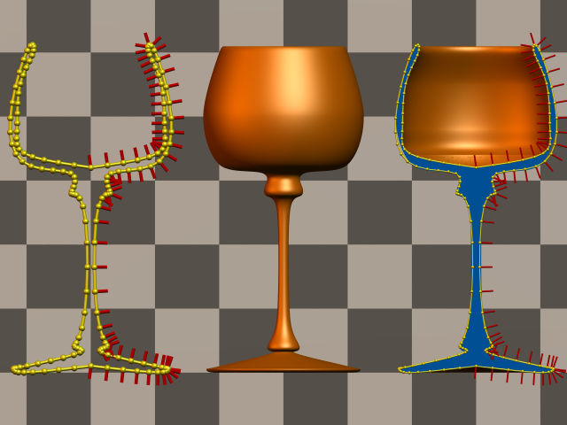
> Also, have you compared the shape with a real lathe object using the same
> control points?
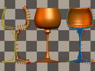
There are slight differences, but both shapes are surprisingly similar.
In the following image the object at the left is the preview of the spline
(made with spheres and cylinders), the object at the middle is the lathe
object made with the same control points (however I replicated the first
and last points and added <-1,0> to them to get approximately the same
result).
The object at the right is the union of both. The lathe has been
intersected with a blue box to show its profile.
Post a reply to this message
Attachments:
Download 'MeshLatheComparison.jpg' (48 KB)
Preview of image 'MeshLatheComparison.jpg'
|
|
| |
| |
|
|
|
|
| |
| |
|
|
Btw, I wonder if this kind of macro could be worth including in the
standard include files.
The only concern I have about it is that it uses the "trick" to calculate
the normal of the spline with the Spline(T+Epsilon)-Spline(T-Epsilon)
formula. What I'm not sure about is the value for 'Epsilon'. I used 1e-5,
but that might sometimes be either too big or too small (due to floating
point number inaccuracies).
The current macro is the following:
---------8<------------8<-------------8<------------8<-----------8<-----
#macro MeshLathe(Spline, VertSteps, HorSteps)
#ifndef(MeshLatheDebug) #local MeshLatheDebug=0; #end
#if(MeshLatheDebug=1 | MeshLatheDebug=2)
#ifndef(MeshLatheDebugRadius) #local MeshLatheDebugRadius=.05; #end
#ifndef(MeshLatheDebugNormalLength) #local MeshLatheDebugNormalLength=.2; #end
union
{ #local Ind1 = 0;
#while(Ind1 < VertSteps)
#local Time1 = Ind1/(VertSteps-1);
#local Coord1 = (Spline(Time1));
#local Tang = (Spline(Time1+1e-5)-Spline(Time1-1e-5));
#local Normal1 = vnormalize(<Tang.y, -Tang.x, 0>);
sphere { Coord1, MeshLatheDebugRadius }
sphere { Coord1*<-1,1,1>, MeshLatheDebugRadius }
#if(MeshLatheDebug=2)
cylinder
{ Coord1, Coord1+Normal1*MeshLatheDebugNormalLength,
MeshLatheDebugRadius*.5
#ifdef(MeshLatheDebugNormalColor)
pigment { rgb MeshLatheDebugNormalColor }
#end
}
#end
#if(Ind1>0)
cylinder { Coord1, oldCoord1, MeshLatheDebugRadius*.5 }
cylinder
{ Coord1*<-1,1,1>, oldCoord1*<-1,1,1>, MeshLatheDebugRadius*.5 }
#end
#local oldCoord1 = Coord1;
#local Ind1 = Ind1+1;
#end
}
#else
mesh
{ #local Ind1 = 0;
#while(Ind1 < VertSteps-1)
#local Time1 = Ind1/(VertSteps-1);
#local Time2 = (Ind1+1)/(VertSteps-1);
#local Coord1 = (Spline(Time1));
#local Tang = (Spline(Time1+1e-5)-Spline(Time1-1e-5));
#local Normal1 = vnormalize(<Tang.y, -Tang.x, 0>);
#local Coord2 = (Spline(Time2));
#local Tang = (Spline(Time2+1e-5)-Spline(Time2-1e-5));
#local Normal2 = vnormalize(<Tang.y, -Tang.x, 0>);
#local Ind2 = 0;
#while(Ind2 < HorSteps-1)
#local Angle1 = 360*Ind2/(HorSteps-1);
#local Angle2 = 360*(Ind2+1)/(HorSteps-1);
#local P1 = vrotate(Coord1, y*Angle1);
#local N1 = vrotate(Normal1, y*Angle1);
#local P2 = vrotate(Coord2, y*Angle1);
#local N2 = vrotate(Normal2, y*Angle1);
#local P3 = vrotate(Coord2, y*Angle2);
#local N3 = vrotate(Normal2, y*Angle2);
#local P4 = vrotate(Coord1, y*Angle2);
#local N4 = vrotate(Normal1, y*Angle2);
#if(MeshLatheDebug>2)
triangle { P1, P2, P3 }
triangle { P3, P4, P1 }
#else
smooth_triangle { P1,N1, P2,N2, P3,N3 }
smooth_triangle { P3,N3, P4,N4, P1,N1 }
#end
#local Ind2 = Ind2+1;
#end
#local Ind1 = Ind1+1;
#end
}
#end
#end
---------8<------------8<-------------8<------------8<-----------8<-----
--
#macro M(A,N,D,L)plane{-z,-9pigment{mandel L*9translate N color_map{[0rgb x]
[1rgb 9]}scale<D,D*3D>*1e3}rotate y*A*8}#end M(-3<1.206434.28623>70,7)M(
-1<.7438.1795>1,20)M(1<.77595.13699>30,20)M(3<.75923.07145>80,99)// - Warp -
Post a reply to this message
|
|
| |
| |
|
|
|
|
| |
| |
|
|
"Warp" <war### [at] tagpovrayorg> wrote in message
news:3c792e92@news.povray.org...
> Btw, I wonder if this kind of macro could be worth including in the
> standard include files.
>
> The only concern I have about it is that it uses the "trick" to
calculate
> the normal of the spline with the Spline(T+Epsilon)-Spline(T-Epsilon)
> formula. What I'm not sure about is the value for 'Epsilon'. I used 1e-5,
> but that might sometimes be either too big or too small (due to floating
> point number inaccuracies).
I remember from my Numerical Analysis courses, that some authors recommend
the optimal size for the epsilon as sqrt(EPS) where EPS is the distance from
1.0 to the next largest floating point number. In a traditional PC, I
believe EPS is approx 2.2e-16, so the optimal epsilon is approximately
1.4e-8
However, I'm recalling all this from my memory, so I can't guarantee that it
is correct :)
I hope you can make some tests for this and report your results...
Fernando.
Post a reply to this message
|
|
| |
| |
|
|
|
|
| |
| |
|
|
> I remember from my Numerical Analysis courses, that some authors recommend
> the optimal size for the epsilon as sqrt(EPS) where EPS is the distance from
> 1.0 to the next largest floating point number. In a traditional PC, I
> believe EPS is approx 2.2e-16, so the optimal epsilon is approximately
> 1.4e-8
Note that we are not using an epsilon value for making comparisons, but
for making vector math which should be as accurate as possible.
The smaller the epsilon value we use for approximating the tangent of the
spline, the more error-prone it will become (due to inaccuracies with very
small values).
When we compare values a really small value is enough (as long as it's
bigger than 0) because we only need to see if two numbers are equal or not.
However in this case we are performing calculations which should not suffer
from inaccuracies.
On the other hand, using an epsilon value which is too big can result in
inaccurate results (because the result deviates too much from the real
tangent).
Thus a proper compromise has to be found.
In the case of splines, which are usually really smooth, we don't really
need a very small epsilon value. Even with rather big values (eg. 1e-3 or
something similar) we still get really acceptable results.
--
#macro M(A,N,D,L)plane{-z,-9pigment{mandel L*9translate N color_map{[0rgb x]
[1rgb 9]}scale<D,D*3D>*1e3}rotate y*A*8}#end M(-3<1.206434.28623>70,7)M(
-1<.7438.1795>1,20)M(1<.77595.13699>30,20)M(3<.75923.07145>80,99)// - Warp -
Post a reply to this message
|
|
| |
| |
|
|
|
|
| |
| |
|
|
In article <3c792e92@news.povray.org>, war### [at] tagpovrayorg says...
> The only concern I have about it is that it uses the "trick" to calculate
> the normal of the spline with the Spline(T+Epsilon)-Spline(T-Epsilon)
> formula. What I'm not sure about is the value for 'Epsilon'.
Why not make it dependent on the distance between the previous and the
next control point?
If it is small (1/100 or so) compared to this distance it should work, no
matter what the absolute scale of the whole thing is.
Has the mesh-approach any advantage over using bicubic patches? The
documentation says bicubic patches are converted to a mesh internally, so
speed should be equal (but I didn't try yet), but parsing should be
faster with patches.
Lutz-Peter
Post a reply to this message
|
|
| |
| |
|
|
|
|
| |
| |
|
|
In article <MPG.16e362bd507e6d0b9896e1@news.povray.org>,
Lutz-Peter Hooge <lpv### [at] gmxde> wrote:
> Why not make it dependent on the distance between the previous and the
> next control point?
Better would be to make it dependant on the distance along the
spline...try an epsilon value and get the distance of the point from the
current point, if it is too small increase it.
But for this application, it isn't very critical...just use a large
enough sample to make errors extremely unlikely.
> Has the mesh-approach any advantage over using bicubic patches? The
> documentation says bicubic patches are converted to a mesh internally, so
> speed should be equal (but I didn't try yet), but parsing should be
> faster with patches.
Not really. Patches are converted to triangles for intersection testing,
but they can do adaptive subdivision on the fly, which slows rendering
but uses less memory and parse time. It is harder to connect them
smoothly, as well.
And a single mesh will have an advantage over a bunch of patches...a
mesh can be very efficient about which triangles it tests, and can use
tricks a union of patches can't. So a mesh will probably render faster.
Then you have the advantage that copies of meshes use very little extra
memory...
--
Christopher James Huff <chr### [at] maccom>
POV-Ray TAG e-mail: chr### [at] tagpovrayorg
TAG web site: http://tag.povray.org/
Post a reply to this message
|
|
| |
| |
|
|
|
|
| |
| |
|
|
in news:3c792e92@news.povray.org Warp wrote:
> The only concern I have about it is that it uses the "trick" to
> calculate
> the normal of the spline with the Spline(T+Epsilon)-Spline(T-Epsilon)
> formula. What I'm not sure about is the value for 'Epsilon'.
Does it matter that much? While building my macro's I settled with half
the spline resolution as I didn't see any difference for smaller values.
Ingo
Post a reply to this message
|
|
| |
| |
|
|
|
|
| |
|
|