|
|
|
|
|
|
| |
| |
|
|
|
|
| |
| |
|
|
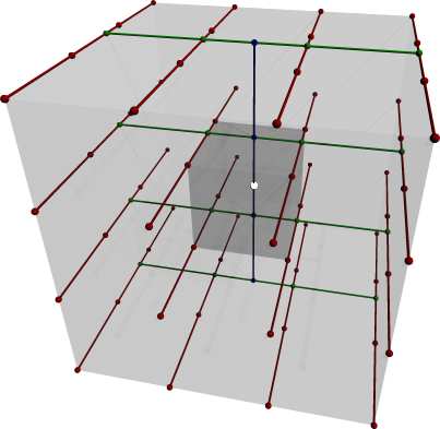
Fairly simple question, but potentially complex:
It works to an extent, but is the pictured scheme entirely correct for
tricubic interpolation? I know there's no problem for linear interpolation
like this, but I'm not quite sure whether it can be extended to cubic. I
think it would be possible to use the basis functions to find each point's
contribution to the interpolated value, but that can overshoot the data
(for a cfd simulation) so it is better to interpolate along a line if
possible - since it's easier to prevent overshooting with four points than
with 64. Maybe (quite possibly) there's a better way yet. Thanks.
- Ricky
Post a reply to this message
Attachments:
Download 'interp.jpg' (15 KB)
Preview of image 'interp.jpg'
|
|
| |
| |
|
|
|
|
| |
| |
|
|
triple_r wrote:
> Fairly simple question, but potentially complex:
> It works to an extent, but is the pictured scheme entirely correct for
> tricubic interpolation? I know there's no problem for linear interpolation
> like this, but I'm not quite sure whether it can be extended to cubic. I
> think it would be possible to use the basis functions to find each point's
> contribution to the interpolated value, but that can overshoot the data
> (for a cfd simulation) so it is better to interpolate along a line if
> possible - since it's easier to prevent overshooting with four points than
> with 64. Maybe (quite possibly) there's a better way yet. Thanks.
> - Ricky
>
>
> ------------------------------------------------------------------------
>
I am not sure if I understand your question. A tricubic interpolation
has 64 parameters. Any set of 64 independent points can fix those.
Often a regular distribution like in your drawing is used, but
technically that is not necessary. If you use these points you can
either choose to fix them in your volume so that when you move a
point the volume deforms with it or you can use them as a control
point in the Bezier sense where you can be sure that the volume
will stay within the control points, that the 'direction' of the
surface will be in the direction of the next point etc.
Such control points will avoid overshooting but you can not fix
the surfaces to go through one specific point. Besides these
common approaches to specify a volume, you can also specify
at each corner the derivatives in three orthogonal directions
plus the three mixed second order derivatives in UV, VW and UW
directions plus the third order derivative in the UVW direction.
That will also fix the 64 parameters. And there are a whole lot
of yet again different approached to fix them.
I don't get what you mean by interpolation along a line. Even if you
can prevent overshoots along that line, nothing prevents overshoots
in any of the two othogonal directions.
To cut a long story short, I think that: you either specify the exact
position of a point after some deformation and then you will get
overshoots, or you use a bezier approach and then the points will
not be exactly in the right place but at least you get a nice
volume where you can easily control the continuity along the outer
surfaces of the 'cubes' you use to describe your volume.
Post a reply to this message
|
|
| |
| |
|
|
|
|
| |
| |
|
|
andrel <a_l### [at] hotmail com> wrote:
> I am not sure if I understand your question.
Entirely my fault. I feel kind of stoopid for asking such a
poorly-phrased question. Sorry you had to do all that typing.
I neglected to state that the points fall on a regular cartesian grid
and I'm interpolating inside a voxel. Regardless of where the points are
defined (center, face, corner) simiple translation can put all points at a
corner, i.e. <0,0,0>, <1,0,0>, <2,0,0>, <3,0,0>, <0,1,0>,etc... (multiplied
by the grid spacing) for sixty-four points. It forms a local 4x4x4 point
box as pictured, then it's a matter of figuring out the value of some point
inside. It's for a fluid simulation as outlined in the Visual Simulation
of Smoke paper, so it is important for stability that the values (of
something like temperature or velocity) interpolated at some point in the
domain do not fall outside of the range of the values actually defined in
that domain. The paper goes into little detail about how they use tricubic
interpolation other than to define a condition for 1-D cubic interpolation
that does not overshoot the data.
Now enters my question whether this is what they had in mind for an
extension to 3-D. My guess (pictured above) is that you can reduce a 3-D
problem to 16 1-D problems which form a 2-D problem. That 2-D problem is 4
1-D problems which reduce the answer to a 1-D problem. If they just
clipped the data to the range in the volume, they wouldn't have gone to the
trouble of defining the 1-D criteria, but I'm not sure my guess is exactly
what they had in mind either. It seems rather anisotropic to favor one
direction over the rest. It's also requires a whole lot of function calls.
This isn't a problem until you do it thousands of times; then you post a
question to a newsgroup asking if there's a better way. I hope that better
defines the question, although I have to wonder if anyone is still reading
this way down here...
Thanks,
Ricky com> wrote:
> I am not sure if I understand your question.
Entirely my fault. I feel kind of stoopid for asking such a
poorly-phrased question. Sorry you had to do all that typing.
I neglected to state that the points fall on a regular cartesian grid
and I'm interpolating inside a voxel. Regardless of where the points are
defined (center, face, corner) simiple translation can put all points at a
corner, i.e. <0,0,0>, <1,0,0>, <2,0,0>, <3,0,0>, <0,1,0>,etc... (multiplied
by the grid spacing) for sixty-four points. It forms a local 4x4x4 point
box as pictured, then it's a matter of figuring out the value of some point
inside. It's for a fluid simulation as outlined in the Visual Simulation
of Smoke paper, so it is important for stability that the values (of
something like temperature or velocity) interpolated at some point in the
domain do not fall outside of the range of the values actually defined in
that domain. The paper goes into little detail about how they use tricubic
interpolation other than to define a condition for 1-D cubic interpolation
that does not overshoot the data.
Now enters my question whether this is what they had in mind for an
extension to 3-D. My guess (pictured above) is that you can reduce a 3-D
problem to 16 1-D problems which form a 2-D problem. That 2-D problem is 4
1-D problems which reduce the answer to a 1-D problem. If they just
clipped the data to the range in the volume, they wouldn't have gone to the
trouble of defining the 1-D criteria, but I'm not sure my guess is exactly
what they had in mind either. It seems rather anisotropic to favor one
direction over the rest. It's also requires a whole lot of function calls.
This isn't a problem until you do it thousands of times; then you post a
question to a newsgroup asking if there's a better way. I hope that better
defines the question, although I have to wonder if anyone is still reading
this way down here...
Thanks,
Ricky
Post a reply to this message
|
|
| |
| |
|
|
|
|
| |
| |
|
|
Also, the small cube is the voxel containing the point to be interpolated,
the larger cube is the 26 surrounding cubes.
- Ricky
Post a reply to this message
|
|
| |
| |
|
|
|
|
| |
| |
|
|
triple_r wrote:
> Also, the small cube is the voxel containing the point to be interpolated,
> the larger cube is the 26 surrounding cubes.
Ok, I didn't get that. Now you mention it is is sort of obvious.
Only, this means that tricubic interpolation is fixed by the
coordinates of the grid points on this center voxel and the
surrounding grid points. You will not be able to get continuity
in any of the edges and faces of the voxels. Take for instance
the upper blue point on the green line. If you approach it from
the underside, from within the grey area, you will find another
point in space after interpolation than if you approach it from
the outside. I am afraid that the only way to get continuity is
to use 64 control points per voxel. That sounds perhaps a bit
worse than it actually is. Most of them depend on other control
points in other voxels. Effectively you have only 8 independent
parameters in this voxel (if you neglect boundaries or assume
a block of voxels that is infinite in all directions).
You may also look into Hermite polynomials as a more compact way
of representing your data.
Post a reply to this message
|
|
| |
| |
|
|
|
|
| |
| |
|
|
triple_r wrote:
> andrel <a_l### [at] hotmailcom> wrote:
>
>>I am not sure if I understand your question.
>
>
> Entirely my fault. I feel kind of stoopid for asking such a
> poorly-phrased question. Sorry you had to do all that typing.
> I neglected to state that the points fall on a regular cartesian grid
> and I'm interpolating inside a voxel. Regardless of where the points are
> defined (center, face, corner) simiple translation can put all points at a
> corner, i.e. <0,0,0>, <1,0,0>, <2,0,0>, <3,0,0>, <0,1,0>,etc... (multiplied
> by the grid spacing) for sixty-four points. It forms a local 4x4x4 point
> box as pictured, then it's a matter of figuring out the value of some point
> inside. It's for a fluid simulation as outlined in the Visual Simulation
> of Smoke paper, so it is important for stability that the values (of
> something like temperature or velocity) interpolated at some point in the
> domain do not fall outside of the range of the values actually defined in
> that domain. The paper goes into little detail about how they use tricubic
> interpolation other than to define a condition for 1-D cubic interpolation
> that does not overshoot the data.
What paper are you referring to?
> Now enters my question whether this is what they had in mind for an
> extension to 3-D. My guess (pictured above) is that you can reduce a 3-D
> problem to 16 1-D problems which form a 2-D problem. That 2-D problem is 4
> 1-D problems which reduce the answer to a 1-D problem.
Yes you can, but why would you? To find the coordinates of a point you
simply multiply with a 4 by 4 by 4 matrix or a vector of 64, depending
on your representation.
> If they just
> clipped the data to the range in the volume, they wouldn't have gone to the
> trouble of defining the 1-D criteria, but I'm not sure my guess is exactly
> what they had in mind either. It seems rather anisotropic to favor one
> direction over the rest.
That only seems so. You interpolate in one direction and use the results
in the next step. In the end every point except the gridpoints at the
faces depend on all 64 points. Also, the result does not depend on the
order you apply the interpolations in.
> It's also requires a whole lot of function calls.
> This isn't a problem until you do it thousands of times; then you post a
> question to a newsgroup asking if there's a better way.
It is only 64 multiplications and some additions, straight from the
linear algebra section of any library.
> I hope that better
> defines the question, although I have to wonder if anyone is still reading
> this way down here...
Well,... I am :)
Post a reply to this message
|
|
| |
| |
|
|
|
|
| |
| |
|
|
andrel wrote:
> triple_r wrote:
>
>> Also, the small cube is the voxel containing the point to be
>> interpolated,
>> the larger cube is the 26 surrounding cubes.
>
>
> Ok, I didn't get that. Now you mention it is is sort of obvious.
> Only, this means that tricubic interpolation is fixed by the
> coordinates of the grid points on this center voxel and the
> surrounding grid points. You will not be able to get continuity
> in any of the edges and faces of the voxels. Take for instance
> the upper blue point on the green line. If you approach it from
> the underside, from within the grey area, you will find another
> point in space after interpolation than if you approach it from
> the outside.
NB I implicitly assumed that the idea was to use the 3 by 3 surround
of a voxel to compute the interpolation within that voxel.
If you repartition the entire volume in 3 by 3 voxel 'supervoxels'
then you will have voxels that fit together. However, all derivatives
may be discontinuous at the joining surface.
Post a reply to this message
|
|
| |
| |
|
|
|
|
| |
| |
|
|
> That only seems so. You interpolate in one direction and use the results
> in the next step. In the end every point except the gridpoints at the
> faces depend on all 64 points. Also, the result does not depend on the
> order you apply the interpolations in.
That's reassuring that the order doesn't make a difference. It seems like
it should give results that make some sense, but it's not immediately
intuitive that the order makes no difference. It can't be perfectly
isotropic with the modified monotonic cubic interpolation though.
> It is only 64 multiplications and some additions, straight from the
> linear algebra section of any library.
Well, it comes out to a whole lot more than that once you do it the
roundabout way. This is the slowest part of the simulation, so I was
wondering if there were better techniques. Reading over the description
again, it seems pretty clear this is what they intended.
Thanks for your help although it looks like I'll still use the same
technique. I tried simplifying it a little by cutting out twenty-four of
the points and turning it into a sort of 3-D '+'. That allows for combined
linear and cubic interpolation. Combined with fourth-order R-K integration
on a ~50x50x50 grid, that makes for roughly 2,500,000 cubic interpolations
per timestep (since the faces and center must be integrated along the
velocity, then the quantities have to be determined after the integration).
I also might pad the array with either zeros or df/dn=0 for boundary
conditions to prevent having to check whether it is outside the domain or
not for each interpolation. Pardon my confusion and thanks again for your
help.
- Ricky
Post a reply to this message
|
|
| |
| |
|
|
|
|
| |
|
|