|
 |
>> As usual I've done a fine job of making myself misunderstood.
>> This is not an animation project, to depict the movements of
>> the parts as they approach a known configuration; this is a
>> design project, to find that configuration.
On 2014-2-26 01:11, scott wrote:
> I think you'll have to explain a bit more what you are doing
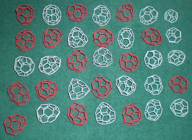
Non-spherical geodesic domes -- dual to figures like the attached --
where the pentagonal hubs are *not* arranged as the vertices of an
icosahedron. The "parts" I mentioned are the hubs, the "nodes" are the
tips of five or six radiating rods; each tip seeks a corresponding tip.
(In general the nodes won't exactly match, and even if they did there
would be an angle between rods; cubic splines will cover both flaws.)
> and what you would like help with.
I want to know how to generate, for each part, a rotation-translation
matrix that brings its nodes nearer to their mates.
At risk of repetition:
In my mental model, such as it is, the attraction between nodes puts a
"force" on each node, which in turn puts a "torque" on the hub.
(Scare-quotes because I don't want to give the body momentum, linear or
angular; I want it to jump to a new position and wait quietly for the
next cycle.)
Torque is a vector, and vectors can be added and rescaled.
But how do I turn the resulting torque vector into a rotation matrix?
> Are the node positions already fixed,
> or is that what you are trying to design?
Each part's nodes are fixed with respect to the part.
What I seek is the positions of the parts with respect to each other.
--
*\\* Anton Sherwood *\\* www.bendwavy.org
Post a reply to this message
Attachments:
Download 'sevenbyfive.jpg' (194 KB)
Preview of image 'sevenbyfive.jpg'
|
|