|
|
|
|
|
|
| |
| |
|
|
|
|
| |
| |
|
|
Am 20.05.2010 10:20, schrieb Invisible:
> Right. So I'm looking at 2.1 V or 2.2 V or thereabouts.
Make sure to leave some margin for tolerances; resistors may have
tolerances up to 10% (though 5% seem to be more common nowadays), and
your power supply might be more (or less) than 5V as well. You don't
want to kill your LED just because its actual "lethal" forward current
happens to be pretty close to nominal, while the power supply and
resistor parameters happen not to be.
Post a reply to this message
|
|
| |
| |
|
|
|
|
| |
| |
|
|
Am 20.05.2010 10:20, schrieb Invisible:
> Now looking at <http://focus.ti.com/lit/ug/scyd013b/scyd013b.pdf>, on
> page 231 (which is actually page 236 of the PDF file), we see that for
> the 74HC00 I'm looking at using, we have Icc <= 0.02 mA, Iol = -Ioh <= 4
> mA, and tPLH = tPHL <= 27 ns. Now, if I actually knew WTF that means...
From the values specified there, I'm pretty sure Icc in this case means
the maximum current that the IC will conduct from Vcc to GND under worst
conditions.
As for Iol and Ioh, these are apparently the maximum currents that the
IC can conduct from Vcc to output pins (in case of positive values), or
from output pins to GND (in case of negative values), though I wouldn't
be too sure whether these are...
(1.a) per-pin or (1.b) per-IC values;
(2.a) maximum values at which output voltage levels are still guaranteed
to be within proper range, (2.b) absolute maximum values the chip is
guaranteed to be able to supply, or (2.c) absolute maximum values the
chip is guaranteed to survive.
tPLH and tPHL are probably signal propagation delays for low-to-high and
high-to-low transitions, respectively.
I'd suggest you search <http://focus.ti.com/general/docs/dsnsuprt.tsp>
for a product-specific datasheet, which will give much more detail, such as:
Absolute maximum ratings (i.e. values that, when exceeded, may cause
permanent damage):
Continuous output current: +/- 25 mA
Continuous current through VCC or GND: +/- 50 mA
That is, for instance, if you plan to drive LEDs with 15 mA through one
of these ICs, you /must not/ connect two in parallel to any output pin,
and you /must not/ try to drive more than 3 LEDs in total per IC (unless
you want to risk chip destriction).
Elextrical characteristics (i.e. values that are guaranteed by the
manufacturer):
Voh (output voltage when pin is high) may (or may not!) drop as low as
3.84 V (given a Vcc of 4.5 V) when sustaining a current of -4 mA (so I'd
expect even lower values when trying to draw -15 mA)
Vol (output voltage when pin is low) may (or may not!) rise as high as
0.33 V (again given a Vcc of 4.5 V) when sustaining a current of +4 mA
(so I'd expect even higher values when trying to draw +15 mA)
That is, driving the LEDs in low-active configuration between Vcc and
output pin is likely to give you a somwehat more predictable voltage.
Post a reply to this message
|
|
| |
| |
|
|
|
|
| |
| |
|
|
Invisible wrote:
>>> OK, so if I'm understanding this right... The 74126 (go look it up)
>>> contains 4 "buffers" - gates who's output is logically equal to their
>>> input. But each gate also has an "enable" pin. When the enable pin is
>>> high, the gate works like normal. When the enable pin goes low, it's
>>> like the output pin isn't connected to anything any more.
>>
>> Yes exactly.
>>
>>> And it seems that this allows you to connect several outputs
>>> together, forming a kind of wired-OR configuration, provided that at
>>> all times only one gate is "enabled".
>>
>> Yep, you could make a simple address decoder logic circuit (ie have a
>> 2 bit binary input to select which of the 4 buffers to enable) - that
>> way you would guarantee only 1 would be active at a time. If you were
>> to connect a 2-bit counter to the 2-bit address lines you would then
>> have a 4-bit parallel to serial converter :-)
>
> I was thinking more about routing bundles of signals from place to
> place. The "obvious" thing to do is use logic gates to combine the
> signals, but I guess using these weird 3-state systems allows you to
> save a few logic gates (and hence ICs, wiring, and ripple time).
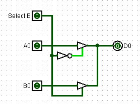
Like this?
(Seems to work in simulation...)
Post a reply to this message
Attachments:
Download 'logic1.png' (2 KB)
Preview of image 'logic1.png'
|
|
| |
| |
|
|
|
|
| |
| |
|
|
> Like this?
>
> (Seems to work in simulation...)
Careful, go much further and you're going to end up designing a RAM chip :-)
Post a reply to this message
|
|
| |
| |
|
|
|
|
| |
| |
|
|
scott wrote:
> Careful, go much further and you're going to end up designing a RAM chip
> :-)
Oh, I won't ever be designing a *chip*. ;-) But I might end up designing
RAM... (That way, at least *I* will know how it works.)
Post a reply to this message
|
|
| |
| |
|
|
|
|
| |
| |
|
|
On 5/20/2010 5:18 AM, Invisible wrote:
> (Seems to work in simulation...)
Unrelated, but tangential, How do you like LogiSim?
--
~Mike
Post a reply to this message
|
|
| |
| |
|
|
|
|
| |
| |
|
|
Mike Raiford wrote:
> Unrelated, but tangential, How do you like LogiSim?
Not very much.
I mean, it *works*, but that's about it. It's really hard work to *do*
anything with it. All gates default to having 5 inputs, no matter how
many times you change it back to 2. All devices default to East
orientation, no matter how many times you change it. Even just moving
part of the circuit to make some room is quite unecessarily difficult.
On top of that, the graphics look horrible, pin labels refuse to display
when you need to see them, it's quite hard to label anything properly,
and it spazzes out if you try to built a latch.
But apart from all that, it works perfectly. :-}
As if the problem of designing complex arrangements of logic wasn't hard
enough to start with...
Post a reply to this message
|
|
| |
| |
|
|
|
|
| |
| |
|
|
scott wrote:
> which is why LEDs don't light up at all below a certain voltage.
I read a book back in high school that talked about electronics and went all
the way from tubes to CMOS FETs, in sufficient detail that I even know *why*
on an atomic level LEDs don't light up below a certain voltage.
Was a really cool book. I wish I remembered the name of it. I was too young
at the time to realize it was exceptional.
--
Darren New, San Diego CA, USA (PST)
Ada - the programming language trying to avoid
you literally shooting yourself in the foot.
Post a reply to this message
|
|
| |
| |
|
|
|
|
| |
| |
|
|
>>> I think I resist any urge to comment on this. Other than "RTFM"
>>
>> I don't think electricity comes with a manual. Neither do ICs, usually...
>
> They do, they are called datasheets.
Datasheets aren't manuals. They assume that you already know what, say,
a Gated D-Latch is, and that you just want to know what its maximum
driving current is or something. If you *don't* already know what a
Gated D-Latch is, the datasheet will be of no use at all. You need
*real* instructions.
>> Hey, what do you *think* I've got a dad for? ;-)
>
> Hard to say, other than the obvious task of a father ;)
Damnit, I said don't answer that. :-(
> Have you ever looked at e.g.
> http://en.wikipedia.org/wiki/File:TTL_npn_nand.svg ?
1. What is this thing?
2. How does it help?
--
http://blog.orphi.me.uk/
http://www.zazzle.com/MathematicalOrchid*
Post a reply to this message
|
|
| |
| |
|
|
|
|
| |
| |
|
|
Am 20.05.2010 19:14, schrieb Orchid XP v8:
>>> I don't think electricity comes with a manual. Neither do ICs,
>>> usually...
>>
>> They do, they are called datasheets.
>
> Datasheets aren't manuals. They assume that you already know what, say,
> a Gated D-Latch is, and that you just want to know what its maximum
> driving current is or something. If you *don't* already know what a
> Gated D-Latch is, the datasheet will be of no use at all. You need
> *real* instructions.
Well, typically the datasheets of stuff like D-latches come with a logic
table.
Post a reply to this message
|
|
| |
| |
|
|
|
|
| |