|
 |
Invisible wrote:
>>> OK, so if I'm understanding this right... The 74126 (go look it up)
>>> contains 4 "buffers" - gates who's output is logically equal to their
>>> input. But each gate also has an "enable" pin. When the enable pin is
>>> high, the gate works like normal. When the enable pin goes low, it's
>>> like the output pin isn't connected to anything any more.
>>
>> Yes exactly.
>>
>>> And it seems that this allows you to connect several outputs
>>> together, forming a kind of wired-OR configuration, provided that at
>>> all times only one gate is "enabled".
>>
>> Yep, you could make a simple address decoder logic circuit (ie have a
>> 2 bit binary input to select which of the 4 buffers to enable) - that
>> way you would guarantee only 1 would be active at a time. If you were
>> to connect a 2-bit counter to the 2-bit address lines you would then
>> have a 4-bit parallel to serial converter :-)
>
> I was thinking more about routing bundles of signals from place to
> place. The "obvious" thing to do is use logic gates to combine the
> signals, but I guess using these weird 3-state systems allows you to
> save a few logic gates (and hence ICs, wiring, and ripple time).
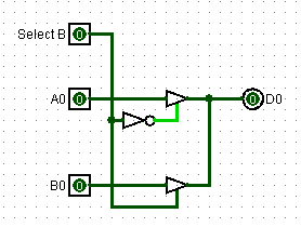
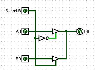
Like this?
(Seems to work in simulation...)
Post a reply to this message
Attachments:
Download 'logic1.png' (2 KB)
Preview of image 'logic1.png'
|
|