|
|
|
|
|
|
| |
| |
|
|
|
|
| |
| |
|
|
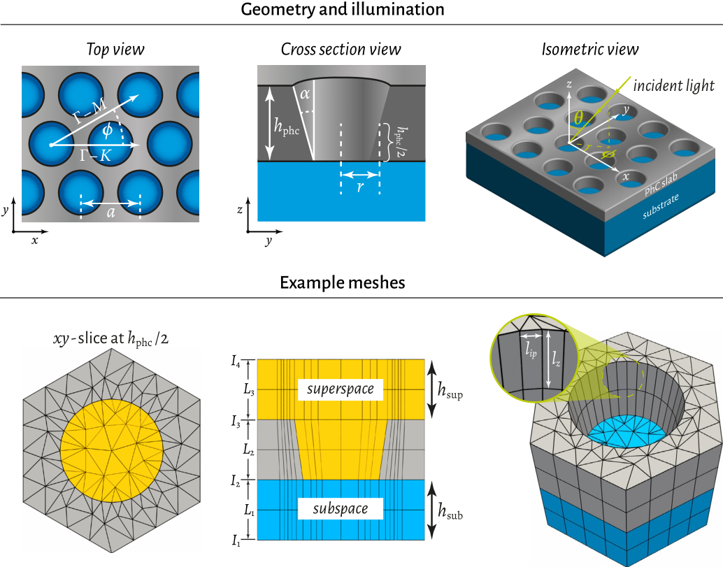
These are some sketches of the geometry, showing the hexagonal unit cell in
which the data is available. The blue part can be omitted in the POV-ray render,
just as the lines that indicate the meshing.
Post a reply to this message
Attachments:
Download 'nanohole_geometry.png' (458 KB)
Preview of image 'nanohole_geometry.png'

|
|
| |
| |
|
|
|
|
| |
| |
|
|
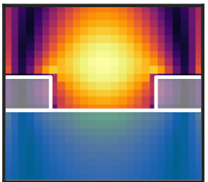
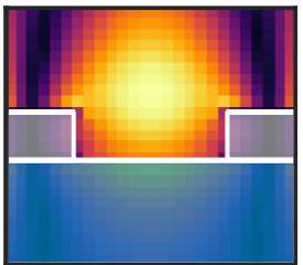
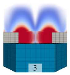
.... and here is a very coarse 2D slice of an example field, just as I imagine it
later in 3D ...
Post a reply to this message
Attachments:
Download 'example_2d_slice_field.png' (10 KB)
Preview of image 'example_2d_slice_field.png'
|
|
| |
| |
|
|
|
|
| |
| |
|
|
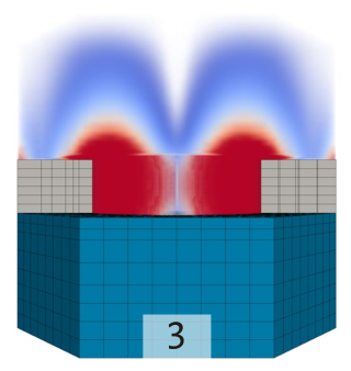
.... and an example of a similar situation which I had rendered in Paraview. Note
that the POV-version should use a different color map (previous post), more
transparent, glowing fields, no blue substrate, no meshing lines, and more unit
cells ...
Post a reply to this message
Attachments:
Download 'example_3d_render_using_paraview.png' (87 KB)
Preview of image 'example_3d_render_using_paraview.png'
|
|
| |
| |
|
|
|
|
| |
| |
|
|
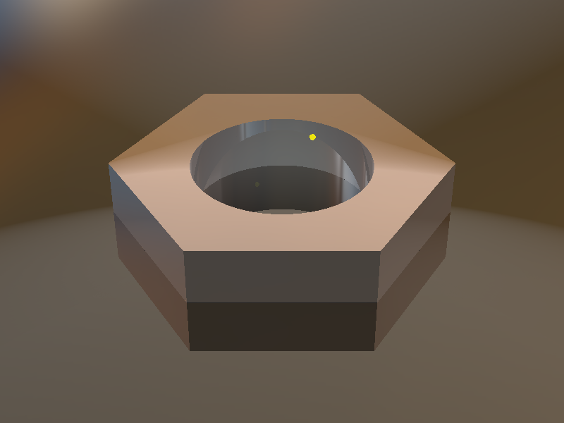
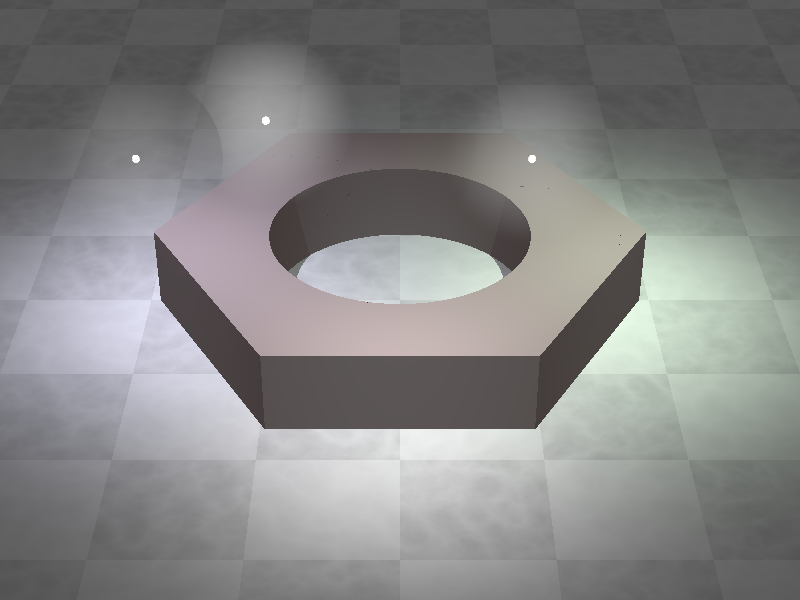
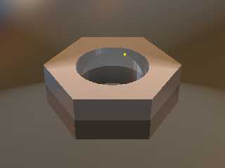
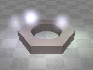
.... and finally a draft of the pov-scene, yet showing only a single unit cell
and a single emitter.
Post a reply to this message
Attachments:
Download 'phc_and_excitation_enhancement.png' (102 KB)
Preview of image 'phc_and_excitation_enhancement.png'
|
|
| |
| |
|
|
|
|
| |
| |
|
|
"cbpypov" <nomail@nomail> wrote:
> .... and here is a very coarse 2D slice of an example field, just as I imagine it
> later in 3D ...
It seems the thing to do is model the hexagonal unit cell, union it as an
all-inclusive object, and then repeat it in a hexagonal arrangement.
I'm also thinking that you probably don't even need to go the df3 file route,
since you're already calculating your field. You can just use that function to
_directly_ define the density of your media.
Likewise, you can use that function to map your colors, and according to the
Bourke site,
"The POVRay file is here: example.pov, note that the density in this example
just controls the emission in the media."
- so the emission brightness can be controlled that way as well.
Just normalize your function so all values are within the 0-1 range.
Hit F1 and type density
then go to the density, media section:
3.7.2.4 Density
"The density statement may begin with an optional density identifier. All
subsequent values modify the defaults or the values in the identifier. The next
item is a pattern type. This is any one of POV-Ray's pattern functions such as
bozo, wood, gradient, waves, etc. Of particular usefulness are the spherical,
planar, cylindrical, and boxed patterns which were previously available only for
use with our discontinued halo feature. All patterns return a value from 0.0 to
1.0. This value is interpreted as the density of the media at that particular
point."
Post a reply to this message
|
|
| |
| |
|
|
|
|
| |
| |
|
|
"Bald Eagle" <cre### [at] netscape net> wrote:
>
> It seems the thing to do is model the hexagonal unit cell, union it as an
> all-inclusive object, and then repeat it in a hexagonal arrangement.
>
> I'm also thinking that you probably don't even need to go the df3 file route,
> since you're already calculating your field. You can just use that function to
> _directly_ define the density of your media.
> Likewise, you can use that function to map your colors, and according to the
> Bourke site,
> "The POVRay file is here: example.pov, note that the density in this example
> just controls the emission in the media."
> - so the emission brightness can be controlled that way as well.
> Just normalize your function so all values are within the 0-1 range.
>
> Hit F1 and type density
> then go to the density, media section:
>
> 3.7.2.4 Density
>
> "The density statement may begin with an optional density identifier. All
> subsequent values modify the defaults or the values in the identifier. The next
> item is a pattern type. This is any one of POV-Ray's pattern functions such as
> bozo, wood, gradient, waves, etc. Of particular usefulness are the spherical,
> planar, cylindrical, and boxed patterns which were previously available only for
> use with our discontinued halo feature. All patterns return a value from 0.0 to
> 1.0. This value is interpreted as the density of the media at that particular
> point."
What you write sounds extremely reasonable to me! I am right now generating the
field data (sorry for the delay, the hard drive of my PC at work crashed
completely ... 1 month before the end of my PhD phase). So I will try to figure
out the density mapping post my results later.
Until then, could someone of you have a look on the things that I tried related
to the emitters: I basically created this macro to generated small spheres with
a glowing "aura":
#macro QuantumDot(Radius, Intensity, Origin)
// The actual quantum dot
sphere{
<0,0,0>, Radius
texture{ Glass2 } // end of texture
translate Origin
} // end of sphere
// The glowing aura
sphere {
<0,0,0>,
Radius* (Intensity*5 + 1)
pigment { rgbt 1 } hollow
interior
{ media
{ emission Intensity
density { spherical
color_map {
[0.0 rgb <0,0,0>]
[0.6 rgb <0., 0., 0>]
[0.7 rgb <0.6, 0.6, 0.6>]
[1.0 rgb <1,1,1>]
}
}
}
}
translate Origin
}
// #end // end of #for loop
#end // ------------------ end of macro
Although it looks quite nice to me, there is the problem that the emitting
spheres do not "overlap" properly (I'd expect that the intensity of the emission
would add up!?). Moreover, I would want a smooth fade-out of the aura, but yet
it is dependent on the intensity: with Intensity=1 it looks fine, while
Intensity=0.4 rather looks like an additional sphere. Please see the attachment.
Any comments greatly appreciated :) net> wrote:
>
> It seems the thing to do is model the hexagonal unit cell, union it as an
> all-inclusive object, and then repeat it in a hexagonal arrangement.
>
> I'm also thinking that you probably don't even need to go the df3 file route,
> since you're already calculating your field. You can just use that function to
> _directly_ define the density of your media.
> Likewise, you can use that function to map your colors, and according to the
> Bourke site,
> "The POVRay file is here: example.pov, note that the density in this example
> just controls the emission in the media."
> - so the emission brightness can be controlled that way as well.
> Just normalize your function so all values are within the 0-1 range.
>
> Hit F1 and type density
> then go to the density, media section:
>
> 3.7.2.4 Density
>
> "The density statement may begin with an optional density identifier. All
> subsequent values modify the defaults or the values in the identifier. The next
> item is a pattern type. This is any one of POV-Ray's pattern functions such as
> bozo, wood, gradient, waves, etc. Of particular usefulness are the spherical,
> planar, cylindrical, and boxed patterns which were previously available only for
> use with our discontinued halo feature. All patterns return a value from 0.0 to
> 1.0. This value is interpreted as the density of the media at that particular
> point."
What you write sounds extremely reasonable to me! I am right now generating the
field data (sorry for the delay, the hard drive of my PC at work crashed
completely ... 1 month before the end of my PhD phase). So I will try to figure
out the density mapping post my results later.
Until then, could someone of you have a look on the things that I tried related
to the emitters: I basically created this macro to generated small spheres with
a glowing "aura":
#macro QuantumDot(Radius, Intensity, Origin)
// The actual quantum dot
sphere{
<0,0,0>, Radius
texture{ Glass2 } // end of texture
translate Origin
} // end of sphere
// The glowing aura
sphere {
<0,0,0>,
Radius* (Intensity*5 + 1)
pigment { rgbt 1 } hollow
interior
{ media
{ emission Intensity
density { spherical
color_map {
[0.0 rgb <0,0,0>]
[0.6 rgb <0., 0., 0>]
[0.7 rgb <0.6, 0.6, 0.6>]
[1.0 rgb <1,1,1>]
}
}
}
}
translate Origin
}
// #end // end of #for loop
#end // ------------------ end of macro
Although it looks quite nice to me, there is the problem that the emitting
spheres do not "overlap" properly (I'd expect that the intensity of the emission
would add up!?). Moreover, I would want a smooth fade-out of the aura, but yet
it is dependent on the intensity: with Intensity=1 it looks fine, while
Intensity=0.4 rather looks like an additional sphere. Please see the attachment.
Any comments greatly appreciated :)
Post a reply to this message
Attachments:
Download 'phc_and_excitation_enhancement.png' (240 KB)
Preview of image 'phc_and_excitation_enhancement.png'
|
|
| |
| |
|
|
|
|
| |
| |
|
|
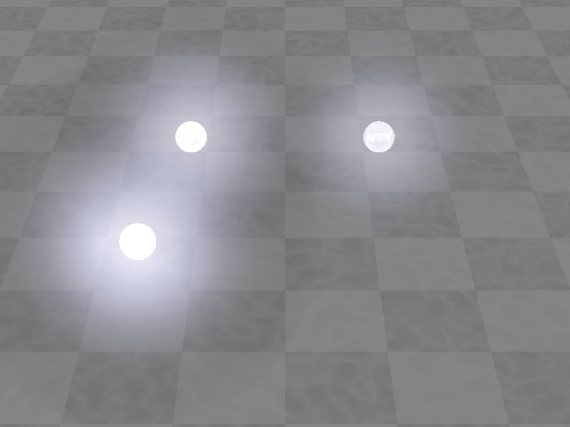
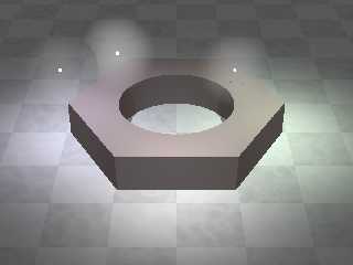
.... and here are the emitters alone and larger:
Post a reply to this message
Attachments:
Download 'quantum_dot.png' (168 KB)
Preview of image 'quantum_dot.png'
|
|
| |
| |
|
|
|
|
| |
| |
|
|
"cbpypov" <nomail@nomail> wrote:
> Although it looks quite nice to me, there is the problem that the emitting
> spheres do not "overlap" properly (I'd expect that the intensity of the emission
> would add up!?). Moreover, I would want a smooth fade-out of the aura, but yet
> it is dependent on the intensity: with Intensity=1 it looks fine, while
> Intensity=0.4 rather looks like an additional sphere. Please see the attachment.
First, you radius is defined as a function of your intensity, so of course they
are linked.
Second, define your density as a function
density { function{Func(x,y,z)}
rather than as spherical - that might help your fading
The following is all speculation:
I have some ambiguity about about the additivity of the emissivity.
[say that 5 times fast]
I think it might be your color map.
You might have to use transmit as part of your rgb[t] designations to get a pure
emission, use no light source, and turn on radiosity.
might need to add a statement about absorption, but I don't know what the
default behaviour is.
Experts are online, waiting to answer your questions in the order you post...
Post a reply to this message
|
|
| |
| |
|
|
|
|
| |
| |
|
|
> First, you radius is defined as a function of your intensity, so of course they
> are linked.
Yes, I thought it might be beneficial if the glowing reaches farther in case of
brigther emitters...
> Second, define your density as a function
> density { function{Func(x,y,z)}
> rather than as spherical - that might help your fading
So I did that using exponential decay from the center and the result is much
better! The macro now reads:
#declare Exp_decay = function {
exp( -(pow(x,2) + pow(y,2) + pow(z,2))*80. )
};
#macro QuantumDot(Radius, Radius_aura, Intensity, Origin)
// The actual quantum dot
sphere{
<0,0,0>, Radius
texture{ Glass2 } // end of texture
translate Origin
} // end of sphere
// The glowing aura
sphere {
<0,0,0>,
Radius_aura*(1+Intensity)
pigment { rgbt 1 } hollow
interior
{ media
{ emission Intensity*5
density {
function { Exp_decay(x,y,z) }
color_map {
[0.0 rgbt <0,0,0,1>]
[0.5 rgbt <0.5, 0.5, 0.7,1>]
[1.0 rgbt <1,1,1,1>]
}
}
}
media
{ absorption 0.2
}
}
translate Origin
}
// #end // end of #for loop
#end // ------------------ end of macro
> The following is all speculation:
> I have some ambiguity about about the additivity of the emissivity.
> [say that 5 times fast]
I was laughing loudly though being alone in the room :D
> I think it might be your color map.
> You might have to use transmit as part of your rgb[t] designations to get a pure
> emission, use no light source, and turn on radiosity.
> might need to add a statement about absorption, but I don't know what the
> default behaviour is.
>
> Experts are online, waiting to answer your questions in the order you post...
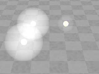
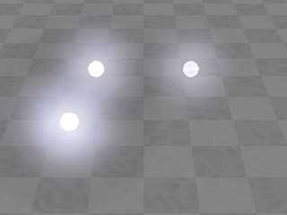
See the attachment: the QDs alone are fine now, but The overlap is not. Setting
the transmittance to either 1 or 0 does not make any difference. I also set an
absorption as you mentioned.
BTW: how can I attach multiple files in one post?
Post a reply to this message
Attachments:
Download 'quantum_dot.png' (206 KB)
Preview of image 'quantum_dot.png'
|
|
| |
| |
|
|
|
|
| |
| |
|
|
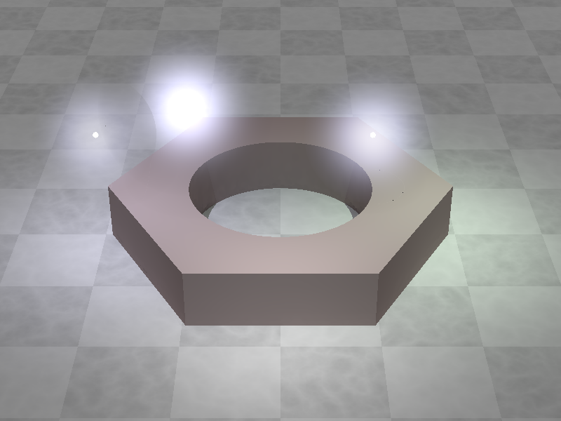
.... here is the overlap problem:
Post a reply to this message
Attachments:
Download 'phc_and_excitation_enhancement.png' (255 KB)
Preview of image 'phc_and_excitation_enhancement.png'
|
|
| |
| |
|
|
|
|
| |
|
|