|
|
|
|
|
|
| |
| |
|
|
|
|
| |
| |
|
|
"Bald Eagle" <cre### [at] netscape net> wrote:
> I had that as part of a mental list to post, but it slipped off...
>
> I was also thinking that if you wanted to represent an emission, you ought to
> use the standard lambda-photon-sine-wave thing
>
> like
> https://physics.aps.org/assets/5f985b1a-28d8-4cb1-89f1-1ae7dedeac6f/e135_2_thumb.png
>
> Just define it as an object that you can replace that quickie Vector () with.
>
> And now I'm off to lunch.
So for the fast case I managed to get rid of the overlap by defining the field
directly in a prism that I scale to the unit cell size, like this
#declare Field_object = prism {
linear_sweep
linear_spline
0., // sweep the following shape from here ...
1., // ... up through here
7, // the number of points making up the shape ...
<0.,0.5>, <0.25,1.>, <0.75,1.>, <1.,0.5>, <0.75,0.>, <0.25,0.>, <0.,0.5>
texture {
finish { diffuse 0 ambient 0 reflection 0 }
pigment {
colour rgbft <1.000,1.000,1.00,0.000,1.000>
}
}
hollow
interior{
ior 1.000
caustics 0.000
dispersion 1.000
dispersion_samples 7.000
fade_power 0.000
fade_distance 0.000
fade_color rgb <0.000,0.000,0.000>
// Red
media {
method 3
intervals 10
samples 1, 1
confidence 0.900
variance 0.008
ratio 0.900
absorption rgb <0,0,0>
emission rgb <1,0,0> * Field_brightness
aa_threshold 0.050
aa_level 4
density {
density_file df3 "efield_energy_in_superspace_R.df3"
interpolate Field_interpolation
}
}
// Green
media {
method 3
intervals 10
samples 1, 1
confidence 0.900
variance 0.008
ratio 0.900
absorption rgb <0,0,0>
emission rgb <0,1,0> * Field_brightness
aa_threshold 0.050
aa_level 4
density {
density_file df3 "efield_energy_in_superspace_G.df3"
interpolate Field_interpolation
}
}
// Blue
media {
method 3
intervals 10
samples 1, 1
confidence 0.900
variance 0.008
ratio 0.900
absorption rgb <0,0,0>
emission rgb <0,0,1> * Field_brightness
aa_threshold 0.050
aa_level 4
density {
density_file df3 "efield_energy_in_superspace_B.df3"
interpolate Field_interpolation
}
}
media {
absorption 0.
}
}
// Set proper size and position
scale field_box_dim
translate field_box_trans
}
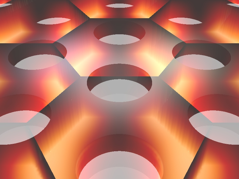
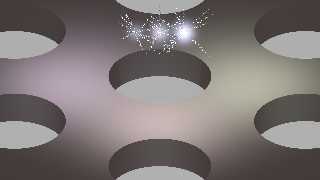
But still a problem is that the "black" parts of the color map are not
transparent (maybe because the density is not exactly 0.0?). So there is a kind
of "box" still visible, which destroys the complete image. See the attachment.
Help! :)
For the emitter thing: yes that "standard lambda-photon-sine-wave thing" would
really be a great thing to have ... er ... how do I do that? :) net> wrote:
> I had that as part of a mental list to post, but it slipped off...
>
> I was also thinking that if you wanted to represent an emission, you ought to
> use the standard lambda-photon-sine-wave thing
>
> like
> https://physics.aps.org/assets/5f985b1a-28d8-4cb1-89f1-1ae7dedeac6f/e135_2_thumb.png
>
> Just define it as an object that you can replace that quickie Vector () with.
>
> And now I'm off to lunch.
So for the fast case I managed to get rid of the overlap by defining the field
directly in a prism that I scale to the unit cell size, like this
#declare Field_object = prism {
linear_sweep
linear_spline
0., // sweep the following shape from here ...
1., // ... up through here
7, // the number of points making up the shape ...
<0.,0.5>, <0.25,1.>, <0.75,1.>, <1.,0.5>, <0.75,0.>, <0.25,0.>, <0.,0.5>
texture {
finish { diffuse 0 ambient 0 reflection 0 }
pigment {
colour rgbft <1.000,1.000,1.00,0.000,1.000>
}
}
hollow
interior{
ior 1.000
caustics 0.000
dispersion 1.000
dispersion_samples 7.000
fade_power 0.000
fade_distance 0.000
fade_color rgb <0.000,0.000,0.000>
// Red
media {
method 3
intervals 10
samples 1, 1
confidence 0.900
variance 0.008
ratio 0.900
absorption rgb <0,0,0>
emission rgb <1,0,0> * Field_brightness
aa_threshold 0.050
aa_level 4
density {
density_file df3 "efield_energy_in_superspace_R.df3"
interpolate Field_interpolation
}
}
// Green
media {
method 3
intervals 10
samples 1, 1
confidence 0.900
variance 0.008
ratio 0.900
absorption rgb <0,0,0>
emission rgb <0,1,0> * Field_brightness
aa_threshold 0.050
aa_level 4
density {
density_file df3 "efield_energy_in_superspace_G.df3"
interpolate Field_interpolation
}
}
// Blue
media {
method 3
intervals 10
samples 1, 1
confidence 0.900
variance 0.008
ratio 0.900
absorption rgb <0,0,0>
emission rgb <0,0,1> * Field_brightness
aa_threshold 0.050
aa_level 4
density {
density_file df3 "efield_energy_in_superspace_B.df3"
interpolate Field_interpolation
}
}
media {
absorption 0.
}
}
// Set proper size and position
scale field_box_dim
translate field_box_trans
}
But still a problem is that the "black" parts of the color map are not
transparent (maybe because the density is not exactly 0.0?). So there is a kind
of "box" still visible, which destroys the complete image. See the attachment.
Help! :)
For the emitter thing: yes that "standard lambda-photon-sine-wave thing" would
really be a great thing to have ... er ... how do I do that? :)
Post a reply to this message
Attachments:
Download 'phc_and_excitation_enhancement.png' (250 KB)
Preview of image 'phc_and_excitation_enhancement.png'
|
|
| |
| |
|
|
|
|
| |
| |
|
|
"cbpypov" <nomail@nomail> wrote:
> But still a problem is that the "black" parts of the color map are not
> transparent (maybe because the density is not exactly 0.0?). So there is a kind
> of "box" still visible, which destroys the complete image. See the attachment.
> Help! :)
Maybe there needs to be a t in one of your rgb statements?
I'll have to look at it when I get back home.
> For the emitter thing: yes that "standard lambda-photon-sine-wave thing" would
> really be a great thing to have ... er ... how do I do that? :)
plot spheres:
http://www.f-lohmueller.de/pov_tut/calc/math_500e.htm
http://news.povray.org/povray.binaries.images/thread/%3Cweb.5926c5ddec053131c437ac910%40news.povray.org%3E/
http://news.povray.org/povray.binaries.images/thread/%3Cweb.58b813187922eedfc437ac910%40news.povray.org%3E/
http://news.povray.org/povray.binaries.images/thread/%3Cweb.5781842fa68f756e5e7df57c0@news.povray.org%3E/
Use a sphere sweep
http://www.povray.org/documentation/view/3.7.1/63/
(instead of points, do a loop with a function evaluating the sine of current
counter value)
parametric isosurface using spline
http://www.econym.demon.co.uk/isotut/more.htm
http://www.econym.demon.co.uk/isotut/splines.htm
I'm sure there may be other clever ways, but fast and simple is usually best.
If you want arrowheads, just define a vector by subtracting the penultimate
sphere from the last sphere to give you a direction, and then start a cone{} at
the last sphere and end at a multiple of that vector.
[That ought to be the correct way to do it...]
Though the arrow out to be pointing straight out...
Post a reply to this message
|
|
| |
| |
|
|
|
|
| |
| |
|
|
Oh, and I found a link to an Angewandte Chemie cover done with POV-Ray that uses
code to make a spring:
http://www.somewhereville.com/?cat=1136
:)
Post a reply to this message
|
|
| |
| |
|
|
|
|
| |
| |
|
|
"Bald Eagle" <cre### [at] netscapenet> wrote:
> Oh, and I found a link to an Angewandte Chemie cover done with POV-Ray that uses
> code to make a spring:
>
> http://www.somewhereville.com/?cat=1136
>
> :)
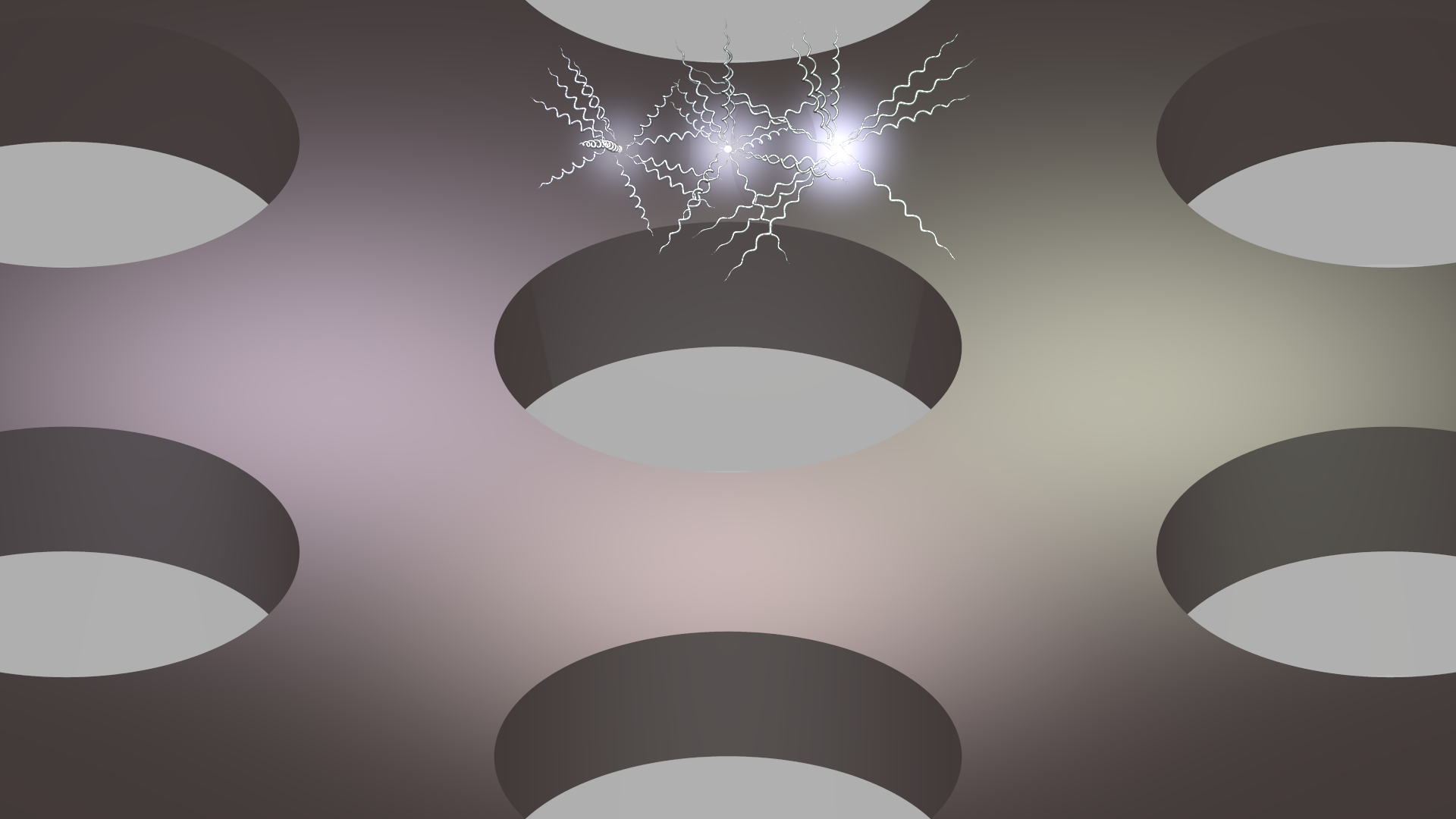
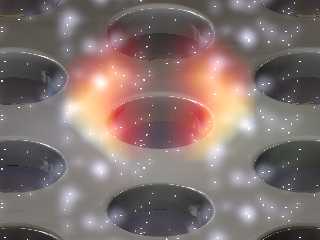
Hey, the spiral thing is really nice. I played around with it, the the result
attached (I added a sin() in the x-displacment of the spheres). But it is
getting rather confusing now :) Maybe I'll stick to the glowing...
Important: could you please post the code you used for the emitters that you
used? I still have the overlap problem, although I set absorption to 0. Since it
is working for you, it will be nice to have the code. Maybe this can also be
applied to field overlap problem...
Where could I integrate a transmittance in the code that uses 3 different media
for RGB (based in Stephen's snippet)? Should there be some kind of colormap?
An new question: how can I achieve a "corner rounding" for the hole? I tried to
subtract an hourglass-like `sor`, but without success :(
Post a reply to this message
Attachments:
Download 'phc_and_excitation_enhancement.png' (453 KB)
Preview of image 'phc_and_excitation_enhancement.png'
|
|
| |
| |
|
|
|
|
| |
| |
|
|
"cbpypov" <nomail@nomail> wrote:
> Hey, the spiral thing is really nice. I played around with it, the the result
> attached (I added a sin() in the x-displacment of the spheres). But it is
> getting rather confusing now :) Maybe I'll stick to the glowing...
#version 3.71;
global_settings {
assumed_gamma 1.0
}
#declare Aspect = image_width/image_height;
camera {
location <0.5, 0, -5>
right x*Aspect
look_at <0, 0, 0>
}
#include "colors.inc"
#declare A = 0.1;
#declare R = 0.01;
#declare Freq = 10;
#declare Photon = union {
#for (X, 0, tau, 0.01)
// plot function
#declare Y = A*sin(Freq*X);
sphere {<X/tau, Y, 0> R}
#end
cylinder {0, <X/tau, Y, 0> R pigment {Red}}
cone {<X/tau, Y, 0>, R*3, <(X/tau)*1.1, Y, 0>, 0 pigment {Red}}
pigment {Yellow}
}
object {Photon}
> Important: could you please post the code you used for the emitters that you
> used? I still have the overlap problem, although I set absorption to 0. Since it
> is working for you, it will be nice to have the code. Maybe this can also be
> applied to field overlap problem...
//##########################################################
#declare Exp_decay = function {
exp( -(pow(x,2) + pow(y,2) + pow(z,2))*80. )
};
#macro QuantumDot(Radius, Radius_aura, Intensity, Origin)
// The actual quantum dot
sphere{
<0,0,0>, Radius
texture{ Glass2 } // end of texture
translate Origin
} // end of sphere
// The glowing aura
sphere {
<0,0,0>,
Radius_aura*(1+Intensity)
pigment { rgbt 1 } hollow
interior
{ media
{ emission Intensity*5
density {
function { Exp_decay(x,y,z) }
color_map {
[0.0 rgbt <0,0,0,1>]
[0.5 rgbt <0.5, 0.5, 0.7,1>]
[1.0 rgbt <1,1,1,1>]
}
}
}
media
{ absorption 0
}
}
translate Origin
}
// #end // end of #for loop
#end // ------------------ end of macro
//##########################################################
> Where could I integrate a transmittance in the code that uses 3 different media
> for RGB (based in Stephen's snippet)? Should there be some kind of colormap?
you have rgb for absorption and transmission - try rgbt.
Also - since you're juxtaposing all those shapes, it may the coincident / near
coincident surface problem.
You may want to do the object as a plane or box with holes, or a hexagonal
pigment pattern instead. You can _really_ fake 3D CSG with well-chosen and
applied pigments and textures.
https://mscharrer.net/povray/bridge/
> An new question: how can I achieve a "corner rounding" for the hole? I tried to
> subtract an hourglass-like `sor`, but without success :(
Step-by-step instructions: :)
http://www.f-lohmueller.de/pov_tut/backgrnd/p_wat4.htm
Post a reply to this message
|
|
| |
| |
|
|
From: Alain
Subject: Re: Example images for the related post: "Rendering an electromagnetic fiel=
Date: 27 Oct 2017 21:02:57
Message: <59f3d741@news.povray.org>
|
|
|
| |
| |
|
|
> "Bald Eagle" <cre### [at] netscapenet> wrote:
>>
>> It seems the thing to do is model the hexagonal unit cell, union it as an
>> all-inclusive object, and then repeat it in a hexagonal arrangement.
>>
>> I'm also thinking that you probably don't even need to go the df3 file route,
>> since you're already calculating your field. You can just use that function to
>> _directly_ define the density of your media.
>> Likewise, you can use that function to map your colors, and according to the
>> Bourke site,
>> "The POVRay file is here: example.pov, note that the density in this example
>> just controls the emission in the media."
>> - so the emission brightness can be controlled that way as well.
>> Just normalize your function so all values are within the 0-1 range.
>>
>> Hit F1 and type density
>> then go to the density, media section:
>>
>> 3.7.2.4 Density
>>
>> "The density statement may begin with an optional density identifier. All
>> subsequent values modify the defaults or the values in the identifier. The next
>> item is a pattern type. This is any one of POV-Ray's pattern functions such as
>> bozo, wood, gradient, waves, etc. Of particular usefulness are the spherical,
>> planar, cylindrical, and boxed patterns which were previously available only for
>> use with our discontinued halo feature. All patterns return a value from 0.0 to
>> 1.0. This value is interpreted as the density of the media at that particular
>> point."
>
>
> What you write sounds extremely reasonable to me! I am right now generating the
> field data (sorry for the delay, the hard drive of my PC at work crashed
> completely ... 1 month before the end of my PhD phase). So I will try to figure
> out the density mapping post my results later.
>
> Until then, could someone of you have a look on the things that I tried related
> to the emitters: I basically created this macro to generated small spheres with
> a glowing "aura":
>
> #macro QuantumDot(Radius, Intensity, Origin)
>
> // The actual quantum dot
> sphere{
> <0,0,0>, Radius
> texture{ Glass2 } // end of texture
> translate Origin
> } // end of sphere
>
> // The glowing aura
> sphere {
> <0,0,0>,
> Radius* (Intensity*5 + 1)
> pigment { rgbt 1 } hollow
> interior
> { media
> { emission Intensity
> density { spherical
> color_map {
> [0.0 rgb <0,0,0>]
> [0.6 rgb <0., 0., 0>]
> [0.7 rgb <0.6, 0.6, 0.6>]
> [1.0 rgb <1,1,1>]
> }
> }
> }
> }
> translate Origin
> }
> // #end // end of #for loop
>
> #end // ------------------ end of macro
>
>
> Although it looks quite nice to me, there is the problem that the emitting
> spheres do not "overlap" properly (I'd expect that the intensity of the emission
> would add up!?). Moreover, I would want a smooth fade-out of the aura, but yet
> it is dependent on the intensity: with Intensity=1 it looks fine, while
> Intensity=0.4 rather looks like an additional sphere. Please see the attachment.
>
> Any comments greatly appreciated :)
>
The media container on the right never overlap the other two, while
there is a visual overlap on the left, and maybe also a physical
overlap. Those overlaping part are known to cause that kind of problems.
You should use a single container. When you have multiple medias within
a single container, they add up.
Multiple densities within the same media will multiply instead.
So, you should place the small spheres, then fill a box with your medias.
You may need to increase the number of samples.
The render time will increase as the number of medias increase.
Post a reply to this message
|
|
| |
| |
|
|
From: Alain
Subject: Re: Example images for the related post: "Rendering an electromagnetic fiel=
Date: 27 Oct 2017 21:06:05
Message: <59f3d7fd$1@news.povray.org>
|
|
|
| |
| |
|
|
> BTW: how can I attach multiple files in one post?
>
From the web interface, it's not possible. You need to use some mail
application, like Thunderbird, or a dedicated news reader.
Post a reply to this message
|
|
| |
| |
|
|
From: Alain
Subject: Re: Example images for the related post: "Rendering an electromagnetic fiel=
Date: 27 Oct 2017 21:09:27
Message: <59f3d8c7$1@news.povray.org>
|
|
|
| |
| |
|
|
> What I forgot: I turned on radiosity as yoou mentioned but without a light
> source the image was black, except for the emitters (if using a black
> background). Why is that?
>
By default, radiosity don't get any illumination from medias. You need
to add "media on" in your radiosity block to enable illumination
computation from medias.
radiosity{media on}
Post a reply to this message
|
|
| |
| |
|
|
|
|
| |
| |
|
|
Alain <kua### [at] videotronca> wrote:
>
> The media container on the right never overlap the other two, while
> there is a visual overlap on the left, and maybe also a physical
> overlap. Those overlaping part are known to cause that kind of problems.
>
> You should use a single container. When you have multiple medias within
> a single container, they add up.
> Multiple densities within the same media will multiply instead.
>
> So, you should place the small spheres, then fill a box with your medias.
> You may need to increase the number of samples.
> The render time will increase as the number of medias increase.
Thank you very much Alain for pointing these things out! I set the radiosity
option (media on) as you said and it seems to work. I think the route is now
pretty much clear to me, except for _one_ thing, and I'd be glad to have your
help one more time...
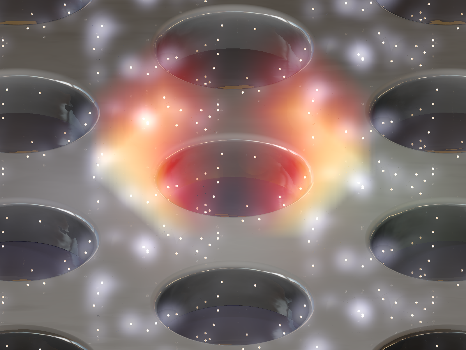
What I did so far is the following:
- I changed to modeling the photonic crystal as a single membrane with hole,
just as Bald Eagle suggested (thanks for this hint and the link to
Lohmuellers hole with edge radius :) ).
- I randomly generated a list of emitter coordinates with intensities
proportional to the field strength at their location.
- I changed the light drastically. It now uses 3 spot lights, an area light
along x-direction, an HDRI light environment, ... and ... each emitter
now features an additional light source proportional to its intensity at
its location (so these are many light sources :) ).
- I tweaked the material parameters to look more realistic.
The result is in the attachment, and I am really satisfied with the improvements
(do you like it?).
So the mentioned final step should be:
- Model the superspace in which the fields are defined as a single object
(I already did, this is just the difference of a large box and the
photonic crystal geometry)
- Define the (1) emitter's glowing spheres and (2) the field renders as
separate media statements inside the interior of this object.
(Their intensities will add up and the overlapping issues will be gone, am I
right Alain?)
THE FINAL PROBLEM:
How do I specify these media inside the interior with the proper alignment? Say
I have a singe field and set it as the density (as before). It will then take
the complete object's vomume, right? How can I get the scaling and the
positioning of these separate media right?
Any help greatly appreciated and thank you so much for guiding me this far. Im
sure it will be beautiful in the end :)
Post a reply to this message
Attachments:
Download '20171028_field_single.png' (1079 KB)
Preview of image '20171028_field_single.png'
|
|
| |
| |
|
|
|
|
| |
| |
|
|
.... and here is again a zip of the scene and the accompanying files:
Post a reply to this message
Attachments:
Download 'povray_phc_scene.zip' (3785 KB)
|
|
| |
| |
|
|
|
|
| |
|
|