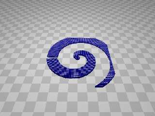
|
 |
#version 3.7;
//------------------------------------------
// SDL for emulating the plotting of an isosurface based on a POV-Ray internal
function
// Bill Walker - September 2017
//------------------------------------------
global_settings {assumed_gamma 1}
#include "colors.inc"
light_source { <-1,8,2> color White}
camera {
location <0, 10, -10>
look_at <0, 0, 0>
}
plane {y, -1 pigment { checker Grey, White }}
/*
isosurface{ function{f_spiral(
x, // PARAM _X
y, // PARAM _Y
z, // PARAM _Z
6, // PARAM (0) distance between windings,
0.2, // PARAM (1) thickness,
15, // PARAM (2) outer diameter of the spiral,
0, // PARAM (3) not used,
0, // PARAM (4) not used,
0.5 // PARAM (5) spiral cross-sectional shape 0-round, 1-square, etc
)}
accuracy 0.01
threshold 0 // default value
max_gradient 21 // high value = more precision = more render time (ideal
value indicated in "messages")
contained_by {sphere {<0,0,0>, 15}}
texture {pigment {Red}}
}
*/
//sphere {<0,0,0>, 15 pigment {rgbt <0.9, 0, 0, 0.4>}}
#macro F_SPIRAL (X, Y, Z, Spacing, Thickness, Dia, Unused1, Unused2, Shape)
#declare r = sqrt (X*X + Z*Z); // Cartesian distance from origin to point
in x-z plane
#if (X = 0 & Z = 0) // Fudges that first awkward starting point by
nudging x from 0 to Epsilon
#declare X = 0.000001;
#end
#declare Theta = atan2 (Z, X); // calculates the angle around the y-axis of
the current point
#declare r = r + Spacing * Theta/tau; // calculates the radius of the current
point on the spiral surface
#declare r2 = mod (r, Spacing) - (Spacing/2); // determines what layer of the
winding is being plotted
//######################################################################################
// This whole block just determines how to plot the cross sectional shape of
the spiral
// Round, square, or somewhere in between
#if (Shape = 1)
#declare r2 = sqrt(r2*r2 + Y*Y);
#elseif (Shape != 0)
#declare temp = 2/Switch;
#declare r2 = pow( (pow(abs(r2), temp) + pow(abs(Y), temp)), 1/temp);
#else
#declare r2 = max (abs(r2), abs(Y));
#declare r = sqrt(X*X + Y*Y + Z*Z);
#end
//######################################################################################
#declare VALUE = -min( Dia - r, Thickness - min(r2, r) );
#declare D1 = sqrt(X*X + Y*Y + Z*Z);
#declare D2 = sqrt(X*X + Y*Y + Z*Z + VALUE*VALUE);
#if (abs (D1 - D2) < STEP)
//If the value is close'nough (TM) [less than the granularity of my plot
(STEP)], plot a sphere
sphere {<0, 0, 0>, 0.03 translate <X, Y, Z> rotate y*Theta}
#end
#end // end macro F_SPIRAL
#declare _Spacing = 3;
#declare _Thickness = 0.1;
#declare _Dia = 4;
#declare _Unused1 = 1;
#declare _Unused2 = 0;
#declare _Shape = 1;
#declare STEP = 0.05;
union {
#for (Y, -_Thickness, _Thickness, STEP)
#for (X, -_Dia, _Dia, STEP)
#for (Z, -_Dia, _Dia, STEP)
// for every <X, Y, Z> point, return a value of the isosurface function
F_SPIRAL (X, Y, Z, _Spacing, _Thickness, _Dia, _Unused1, _Unused2, _Shape)
#end
#end
#end
texture {pigment {rgb <0, 0, 0.5>} finish {specular 0.4} }
no_shadow
}
Post a reply to this message
Attachments:
Download 'emulated_spiral_0.png' (245 KB)
Preview of image 'emulated_spiral_0.png'

|
 |


![]()