 |
 |
|
 |
|
 |
|  |
|  |
|
 |
|
 |
|  |
|  |
|
 |
"- I have tried to show how one can construct the control grid so that the
patches are joined smoothly. All the 8 control points surrounding each corner of
the patches are placed in the same plane."
Thanks - this may help me re-think things.
Can you elaborate a little bit on the implied relationship between the small
vectors between the corner and control points, and the larger vector between
corners is? And why?
I understand the necessity of having the same slope which I believe is what the
small patch shows, and can understand that in isolation, but I haven't yet made
the connection to understand the relation between that and the large vectors.
Post a reply to this message
|
 |
|  |
|  |
|
 |
|
 |
|  |
|  |
|
 |
"Bald Eagle" <cre### [at] netscape net> wrote:
> "- I have tried to show how one can construct the control grid so that the
> patches are joined smoothly. All the 8 control points surrounding each corner of
> the patches are placed in the same plane."
>
> Thanks - this may help me re-think things.
>
> Can you elaborate a little bit on the implied relationship between the small
> vectors between the corner and control points, and the larger vector between
> corners is? And why?
>
> I understand the necessity of having the same slope which I believe is what the
> small patch shows, and can understand that in isolation, but I haven't yet made
> the connection to understand the relation between that and the large vectors.
I assume that you are looking at my 'Bezier_Patches_Stitched' files.
IIRC I added the large vectors as a suggestion for how one can create the
smaller vectors between the points in the control grid around the white corner
points. (The positions for these white corner points were specified "manually".)
The white corner points, together with their corresponding two small vectors,
defines the planes for the 8 control points surrounding each corner point. The
small vectors are also used to control the distances between these control
points.
AFAIK it is common to let the small vectors have the same direction as the large
vectors and to let their lengths be 1/6 of the length of the large vectors.
But I think that one can choose other orientations and lengths for the small
vectors (but I have not had time to experiment with this yet).
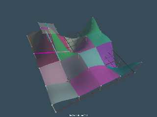
In the attached image I have given each Bezier patch a random color and placed
the camera at a different position.
--
Tor Olav
http://subcube.com net> wrote:
> "- I have tried to show how one can construct the control grid so that the
> patches are joined smoothly. All the 8 control points surrounding each corner of
> the patches are placed in the same plane."
>
> Thanks - this may help me re-think things.
>
> Can you elaborate a little bit on the implied relationship between the small
> vectors between the corner and control points, and the larger vector between
> corners is? And why?
>
> I understand the necessity of having the same slope which I believe is what the
> small patch shows, and can understand that in isolation, but I haven't yet made
> the connection to understand the relation between that and the large vectors.
I assume that you are looking at my 'Bezier_Patches_Stitched' files.
IIRC I added the large vectors as a suggestion for how one can create the
smaller vectors between the points in the control grid around the white corner
points. (The positions for these white corner points were specified "manually".)
The white corner points, together with their corresponding two small vectors,
defines the planes for the 8 control points surrounding each corner point. The
small vectors are also used to control the distances between these control
points.
AFAIK it is common to let the small vectors have the same direction as the large
vectors and to let their lengths be 1/6 of the length of the large vectors.
But I think that one can choose other orientations and lengths for the small
vectors (but I have not had time to experiment with this yet).
In the attached image I have given each Bezier patch a random color and placed
the camera at a different position.
--
Tor Olav
http://subcube.com
Post a reply to this message
Attachments:
Download 'colored_bezier_patches_stitched.png' (275 KB)
Preview of image 'colored_bezier_patches_stitched.png'

|
 |
|  |
|  |
|
 |
|
 |
|  |
|  |
|
 |
"Tor Olav Kristensen" <tor### [at] TOBEREMOVEDgmail com> wrote:
> "Bald Eagle" <cre### [at] netscape com> wrote:
> "Bald Eagle" <cre### [at] netscape net> wrote:
> ...
> ...
> In the attached image I have given each Bezier patch a random color and placed
> the camera at a different position.
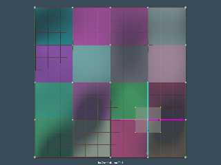
And here's an image where the camera is placed above the colored Bezier patches.
--
Tor Olav
http://subcube.com net> wrote:
> ...
> ...
> In the attached image I have given each Bezier patch a random color and placed
> the camera at a different position.
And here's an image where the camera is placed above the colored Bezier patches.
--
Tor Olav
http://subcube.com
Post a reply to this message
Attachments:
Download 'colored_bezier_patches_stitched_above.png' (252 KB)
Preview of image 'colored_bezier_patches_stitched_above.png'

|
 |
|  |
|  |
|
 |
|
 |
|  |
|  |
|
 |
"Tor Olav Kristensen" <tor### [at] TOBEREMOVEDgmail com> wrote:
> "Tor Olav Kristensen" <tor### [at] TOBEREMOVEDgmail com> wrote:
> "Tor Olav Kristensen" <tor### [at] TOBEREMOVEDgmail com> wrote:
> > BGimeno <bru### [at] gmail com> wrote:
> > BGimeno <bru### [at] gmail com> wrote:
> > > Can someone think of a better way for cover the gaps left by these
> > > sphere_sweep (cubic_spline) curves with bicubic_patch?.
> > > ...
> > > ...
> > I've now made some more images where I've tried to illustrate this better.
> >
> > I'll post them here.
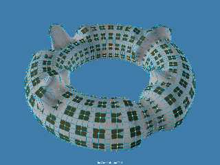
Here's an image where the planes for the control grid points around the Bezier
patch corners are shown as dark squares. I've also added spheres at the control
grid points.
Perhaps I've now posted too many images about stitching of bicubic Bezier
patches...
--
Tor Olav
http://subcube.com com> wrote:
> > > Can someone think of a better way for cover the gaps left by these
> > > sphere_sweep (cubic_spline) curves with bicubic_patch?.
> > > ...
> > > ...
> > I've now made some more images where I've tried to illustrate this better.
> >
> > I'll post them here.
Here's an image where the planes for the control grid points around the Bezier
patch corners are shown as dark squares. I've also added spheres at the control
grid points.
Perhaps I've now posted too many images about stitching of bicubic Bezier
patches...
--
Tor Olav
http://subcube.com
Post a reply to this message
Attachments:
Download 'bicubicbezierpatches_controlgridplanes.png' (799 KB)
Preview of image 'bicubicbezierpatches_controlgridplanes.png'

|
 |
|  |
|  |
|
 |
|
 |
|  |
|  |
|
 |
"Tor Olav Kristensen" <tor### [at] TOBEREMOVEDgmail com> wrote:
> I assume that you are looking at my 'Bezier_Patches_Stitched' files.
Yes. They were, in fact, the motivation for my original attempts at stitching
9 patches together.
> (The positions for these white corner points were specified "manually".)
Yes, that would make sense.
> The
> small vectors are also used to control the distances between these control
> points.
Mmmmmm... I'll have to think about that.
> AFAIK it is common to let the small vectors have the same direction as the large
> vectors and to let their lengths be 1/6 of the length of the large vectors.
That makes sense from what I've tried to do, and is consistent with your
diagrams / renders.
> But I think that one can choose other orientations and lengths for the small
> vectors (but I have not had time to experiment with this yet).
Yes, and I think that I may have tried to bite off more than I could chew at the
time.
How did you smoothly connect the corner points in
http://news.povray.org/web.5b7398619b869b61264be49d0%40news.povray.org ?
Is that a bezier spline sphere-sweep?
[Is it /beh-ZHEER/?]
I spent some time pondering the boundary conditions, and how to process 16
patches like the stitched renders.
What I've come up with is to
create an array of 25 corner points
create an array of 16 points, and "copy" the relevant corner points into the
appropriate places
calculate the linear vectors between the corners of each side
set the control points on those sides to 1/3 and 2/3 of the vector
Use those control points to interpolate the 4 inner control points in an
analogous manner
I hope to get a little bit more time tonight to try and implement that, and see
how it goes.
Then I can start to think about how to write a macro and set up a data structure
to instantiate arbitrarily selected patches, given the corner points. It's the
lone corners and edges that might be tricky for me.
Now, having better grasped what you were doing here, I'd say that based on my
reading, this would give "G1 continuity".
I think that my first time approaching this, I was trying to use 3x3 patches to
give 4 control points and then do deCastejau to subdivide the super-pseudo
Bezier spline suggested by those 4 points so that I could interpolate the inner
control points of the edges in a "Bezier manner", if that makes sense.
Then having a series of X-alined splines, I could use all of those control
points to do the same with the z-aligned splines
But there may be an inherent error in trying to do it that way. com> wrote:
> I assume that you are looking at my 'Bezier_Patches_Stitched' files.
Yes. They were, in fact, the motivation for my original attempts at stitching
9 patches together.
> (The positions for these white corner points were specified "manually".)
Yes, that would make sense.
> The
> small vectors are also used to control the distances between these control
> points.
Mmmmmm... I'll have to think about that.
> AFAIK it is common to let the small vectors have the same direction as the large
> vectors and to let their lengths be 1/6 of the length of the large vectors.
That makes sense from what I've tried to do, and is consistent with your
diagrams / renders.
> But I think that one can choose other orientations and lengths for the small
> vectors (but I have not had time to experiment with this yet).
Yes, and I think that I may have tried to bite off more than I could chew at the
time.
How did you smoothly connect the corner points in
http://news.povray.org/web.5b7398619b869b61264be49d0%40news.povray.org ?
Is that a bezier spline sphere-sweep?
[Is it /beh-ZHEER/?]
I spent some time pondering the boundary conditions, and how to process 16
patches like the stitched renders.
What I've come up with is to
create an array of 25 corner points
create an array of 16 points, and "copy" the relevant corner points into the
appropriate places
calculate the linear vectors between the corners of each side
set the control points on those sides to 1/3 and 2/3 of the vector
Use those control points to interpolate the 4 inner control points in an
analogous manner
I hope to get a little bit more time tonight to try and implement that, and see
how it goes.
Then I can start to think about how to write a macro and set up a data structure
to instantiate arbitrarily selected patches, given the corner points. It's the
lone corners and edges that might be tricky for me.
Now, having better grasped what you were doing here, I'd say that based on my
reading, this would give "G1 continuity".
I think that my first time approaching this, I was trying to use 3x3 patches to
give 4 control points and then do deCastejau to subdivide the super-pseudo
Bezier spline suggested by those 4 points so that I could interpolate the inner
control points of the edges in a "Bezier manner", if that makes sense.
Then having a series of X-alined splines, I could use all of those control
points to do the same with the z-aligned splines
But there may be an inherent error in trying to do it that way.
Post a reply to this message
|
 |
|  |
|  |
|
 |
|
 |
|  |
|  |
|
 |
"Bald Eagle" <cre### [at] netscape net> wrote:
> I spent some time pondering the boundary conditions, and how to process 16
> patches like the stitched renders.
> What I've come up with is to
> create an array of 25 corner points
> create an array of 16 points, and "copy" the relevant corner points into the
> appropriate places
> calculate the linear vectors between the corners of each side
> set the control points on those sides to 1/3 and 2/3 of the vector
> Use those control points to interpolate the 4 inner control points in an
> analogous manner
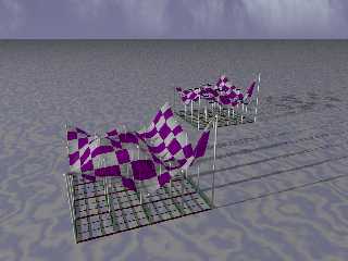
So, I tried a slight modification of the above, following your suggestion, and
what your diagrams/renders imply, and I got 16 connecting patches - but with
sharp seams.
I used 4 vectors describing the edges between the 4 corners, and divided them by
3. I then used those vectors to describe the control points by adding them to
the corners, and adding 2 vectors to a corner to get the 4 inner control points.
It makes sense that it's not smooth, or curved, because everything is just on a
line, and the non-corner control points aren't really control points by this
method - they're just passively following along with the corners.
So I ignored the y part of the vectors and just made "level" sub-patches, and
that seemed to give me something resembling your stitched patch render.
I know I'm still probably a ways off from what you've got - and pretty far off
from what I originally envisioned, but that might possibly be overkill. net> wrote:
> I spent some time pondering the boundary conditions, and how to process 16
> patches like the stitched renders.
> What I've come up with is to
> create an array of 25 corner points
> create an array of 16 points, and "copy" the relevant corner points into the
> appropriate places
> calculate the linear vectors between the corners of each side
> set the control points on those sides to 1/3 and 2/3 of the vector
> Use those control points to interpolate the 4 inner control points in an
> analogous manner
So, I tried a slight modification of the above, following your suggestion, and
what your diagrams/renders imply, and I got 16 connecting patches - but with
sharp seams.
I used 4 vectors describing the edges between the 4 corners, and divided them by
3. I then used those vectors to describe the control points by adding them to
the corners, and adding 2 vectors to a corner to get the 4 inner control points.
It makes sense that it's not smooth, or curved, because everything is just on a
line, and the non-corner control points aren't really control points by this
method - they're just passively following along with the corners.
So I ignored the y part of the vectors and just made "level" sub-patches, and
that seemed to give me something resembling your stitched patch render.
I know I'm still probably a ways off from what you've got - and pretty far off
from what I originally envisioned, but that might possibly be overkill.
Post a reply to this message
Attachments:
Download '12_smooth_bicubic_patches.png' (604 KB)
Preview of image '12_smooth_bicubic_patches.png'

|
 |
|  |
|  |
|
 |
|
 |
|  |
|  |
|
 |
I just added some code to draw the Bezier splines across the patch, using Cousin
Ricky's spheresweep.inc v1.2 from the Object Collection.
The splines don't quite line up - but I suppose, more concerning is that the
splines don't intersect with the corner points.
Probably just some wee little bug in there somewhere.
I'm using the web interface, so I can't rename the message title.
MAYBE I might try to code up a quick Bezier spline macro, if the formula I found
here:
http://wiki.povray.org/content/HowTo:Use_Splines_and_Bezier_Curves
(with the bad math code)
is correct.
P(t) = A*pow((1-t),3) + 3*B*t*pow((1-t),2) + 3*C*pow(t,2)*(1-t) + D*pow(t,3)
which seems to jive with
http://idav.ucdavis.edu/education/CAGDNotes/Matrix-Cubic-Bezier-Curve/img1.gif
Post a reply to this message
|
 |
|  |
|  |
|
 |
|
 |
|  |
|  |
|
 |
Whoops.
Render attached.
Post a reply to this message
Attachments:
Download '12_smooth_bicubic_patches.png' (988 KB)
Preview of image '12_smooth_bicubic_patches.png'

|
 |
|  |
|  |
|
 |
|
 |
|  |
|  |
|
 |
So, I played with some parametric Bezier splines, and that went -- horribly.
:D
But it hinted at the source of the problem - the interpolated control points are
control points - NOT on the surface of the patch - so a spline based on those
doesn't touch the surface.
I got rid of the intermediate sweeps and all is well.
Ricky's off the hook.
Good job.
:)
Post a reply to this message
Attachments:
Download '12_smooth_bicubic_patches.png' (963 KB)
Preview of image '12_smooth_bicubic_patches.png'

|
 |
|  |
|  |
|
 |
From: Thomas de Groot
Subject: Re: Smoothing bicubic_patchs. A pain.
Date: 19 Aug 2018 02:38:45
Message: <5b791075@news.povray.org>
|
|
 |
|  |
|  |
|
 |
On 18-8-2018 23:14, Bald Eagle wrote:
> So, I played with some parametric Bezier splines, and that went -- horribly.
> :D
>
> But it hinted at the source of the problem - the interpolated control points are
> control points - NOT on the surface of the patch - so a spline based on those
> doesn't touch the surface.
>
> I got rid of the intermediate sweeps and all is well.
>
> Ricky's off the hook.
> Good job.
>
> :)
>
Well done, sir! Well done!
Last night, I dreamed about Klein Bottles. That would be a hellish job
to model I guess. ;-)
--
Thomas
Post a reply to this message
|
 |
|  |
|  |
|
 |
|
 |
|  |


![]()