|
|
|
|
|
|
| |
| |
|
|
|
|
| |
| |
|
|
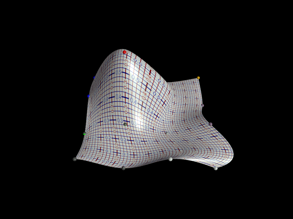
So, the interpolation is still flailing wildly, for some reason, and it will
likely be some time before I get a real feel for what this whole Thomas
Algorithm _does_, and why it's spazzing out.
It was mentioned that a condition for it stability is to stay away from 0, and
have |b| > |a| + |c|. Still pondering that, but I flipped my column
interpolations upside down and it's a tiny bit better.
Might try to tone it down a bit and see about doing some animation on it, just
to see how it looks.
Post a reply to this message
Attachments:
Download '9smoothbicubicpatches_revised_columnsl2h.png' (301 KB)
Preview of image '9smoothbicubicpatches_revised_columnsl2h.png'
|
|
| |
| |
|
|
|
|
| |
| |
|
|
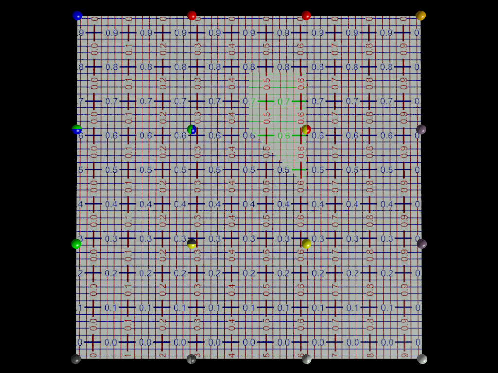
OK, the disproportionate bulge was due to a stray holdover number.
Now I can't for the life of me figure out what that flaw in the uv-mapping is
due to. I've been over it all a dozen times. Replaced patches B and E with
code copied directly from the other unflawed patches.
It's always _something_.
Still not sure exactly why my interior and exterior textures are reversed.
(The blue & red grid is the interior)
Tried reversing my uv vectors so they went counterclockwise, and that just
turned the map, didn't invert inside/outside.
Getting close, though. Getting very very close.
Post a reply to this message
Attachments:
Download '9smoothbicubicpatches_revised.png' (570 KB)
Preview of image '9smoothbicubicpatches_revised.png'
|
|
| |
| |
|
|
|
|
| |
| |
|
|
"Bald Eagle" <cre### [at] netscape net> wrote:
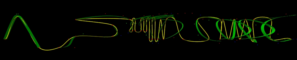
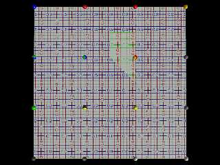
I also made a rough copy of the spline points that LeForgeron uses to run his
splines around and through, and ran the interpolation macro over it - 0 to 48
points, step 4.
Kiiiiinda wild. net> wrote:
I also made a rough copy of the spline points that LeForgeron uses to run his
splines around and through, and ran the interpolation macro over it - 0 to 48
points, step 4.
Kiiiiinda wild.
Post a reply to this message
Attachments:
Download 'leforgeron_spline_cropped.jpg' (63 KB)
Preview of image 'leforgeron_spline_cropped.jpg'

|
|
| |
| |
|
|
|
|
| |
| |
|
|
On 3/10/2016 9:07 PM, Bald Eagle wrote:
> "Bald Eagle" <cre### [at] netscapenet> wrote:
> I also made a rough copy of the spline points that LeForgeron uses to run his
> splines around and through, and ran the interpolation macro over it - 0 to 48
> points, step 4.
> Kiiiiinda wild.
>
He was playing dominoes and chapped the table? :-)
What do the colours represent?
--
Regards
Stephen
Post a reply to this message
|
|
| |
| |
|
|
|
|
| |
| |
|
|
Stephen <mca### [at] aolcom> wrote:
> What do the colours represent?
The Larger red points are the point array, the yellow spline is pov's cubic
spline & my sphere+cylinder sweep.
The green spline is a series of bicubic_patch ribbons generated from the data
points and my interpolated control points. The control points are color coded by
segment red-1 green-2 blue-3 - yellow-data.
Post a reply to this message
|
|
| |
| |
|
|
|
|
| |
| |
|
|
On 3/10/2016 11:16 PM, Bald Eagle wrote:
> Stephen <mca### [at] aolcom> wrote:
>
>> What do the colours represent?
>
>
> The Larger red points are the point array, the yellow spline is pov's cubic
> spline & my sphere+cylinder sweep.
> The green spline is a series of bicubic_patch ribbons generated from the data
> points and my interpolated control points. The control points are color coded by
> segment red-1 green-2 blue-3 - yellow-data.
>
>
>
>
It looks "interesting". A stunt plane's path and the pennant it's towing.
I know, I know. "Take more water with it." :)
--
Regards
Stephen
Post a reply to this message
|
|
| |
| |
|
|
|
|
| |
| |
|
|
Le 10/03/2016 22:07, Bald Eagle a écrit :
> "Bald Eagle" <cre### [at] netscapenet> wrote:
> I also made a rough copy of the spline points that LeForgeron uses to run his
> splines around and through, and ran the interpolation macro over it - 0 to 48
> points, step 4.
> Kiiiiinda wild.
>
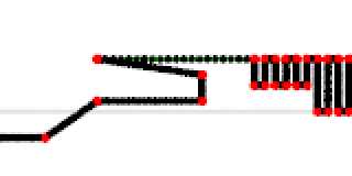
The end should be a closed loop.... at least the yellow does not loop...
you seems to have problem with high frequency alternated position (center)
And it's hard to check/see the green part with a perspective camera (I used
orthographic)
Post a reply to this message
Attachments:
Download 'leforgeronspline09.png' (7 KB)
Preview of image 'leforgeronspline09.png'
|
|
| |
| |
|
|
|
|
| |
| |
|
|
Le_Forgeron <jgr### [at] freefr> wrote:
> The end should be a closed loop....
How does it close?
Do you go up from the base, then around clockwise to the same point, then out to
that tail, or
over and around counterclockwise, like a cursive "e" ?
> you seems to have problem with high frequency alternated position (center)
There's some sort of anomaly in my my interpolation macro that I haven't figured
out yet. That first segment of the Bezier curve goes berserk.
> And it's hard to check/see the green part with a perspective camera (I used
orthographic)
It's a thin Bezier patch, so it would probably disappear completely if I used
orthographic. I haven't written a macro to plot out the Bezier-type spline
using the control points, so in order to get the "right" curvature, I used
POV-Ray's bicubic patch. It does the job well enough to show that the control
points are OFF. :D
Post a reply to this message
|
|
| |
| |
|
|
|
|
| |
| |
|
|
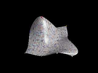
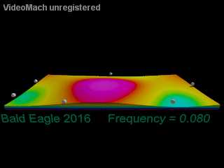
So here's the latest development in the visualization of the plate.
Surfing around Paul Nylander's pages helped me stretch my brain and get me back
on the proper track.
The "data" is all cosine waves that are ballparked to simulate the actual
vibration data, since the isosurface needs the whole wave to plot out the
interference patterns.
100 frames, the height of the flexing ranges from blue to purple.
Took about 40 min to render all the frames.
I'll leave it like for now until I get a few other things worked out - like the
discombobulated Bezier patches and the spline interpolation.
Post a reply to this message
Attachments:
Download 'side_view.gif' (992 KB)
Preview of image 'side_view.gif'
|
|
| |
| |
|
|
|
|
| |
| |
|
|
Although this looks ripe for experimentation:
http://www.f-lohmueller.de/pov_tut/all_shapes/shapes710e.htm
Post a reply to this message
|
|
| |
| |
|
|
|
|
| |