|
|
|
|
|
|
| |
| |
|
|
|
|
| |
| |
|
|
Hello,

I have a surface defined by a set of points <x,y,z> and for each point,
its color.

In your opinion, which object/method is the most appropriate to
represent such a surface?


--
Kurtz le pirate
Compagnie de la Banquise
Post a reply to this message
|
|
| |
| |
|
|
|
|
| |
| |
|
|
kurtz le pirate <kur### [at] gmail com> wrote:
> Hello,
>
> I have a surface defined by a set of points <x,y,z> and for each point,
> its color.
>
> In your opinion, which object/method is the most appropriate to
> represent such a surface?
I'm thinking that the most straightforward thing would be to use
smooth_triangles.
Alternately, maybe you could set up a network of bezier patches, and use your
color information to render a separate scene of boxes that would give you an
image to use as an image_map for uv_mapping your bezier patch union {}.
Might be able to do something with splines and functions ....
It all may depend on how many points you have. com> wrote:
> Hello,
>
> I have a surface defined by a set of points <x,y,z> and for each point,
> its color.
>
> In your opinion, which object/method is the most appropriate to
> represent such a surface?
I'm thinking that the most straightforward thing would be to use
smooth_triangles.
Alternately, maybe you could set up a network of bezier patches, and use your
color information to render a separate scene of boxes that would give you an
image to use as an image_map for uv_mapping your bezier patch union {}.
Might be able to do something with splines and functions ....
It all may depend on how many points you have.
Post a reply to this message
|
|
| |
| |
|
|
|
|
| |
| |
|
|
Hi,

Bald Eagle writes:
> kurtz le pirate wrote:
>> I have a surface defined by a set of points <x,y,z> and for each point
,
>> its color.
>>
>> In your opinion, which object/method is the most appropriate to
>> represent such a surface?
>
> I'm thinking that the most straightforward thing would be to use
> smooth_triangles.
>
> Alternately, maybe you could set up a network of bezier patches, and us
e your
> color information to render a separate scene of boxes that would give y
ou an
> image to use as an image_map for uv_mapping your bezier patch union {}.

>
> Might be able to do something with splines and functions ....
>
> It all may depend on how many points you have.

For example, *.TRI format of 3D shapes contain <x,y,z> coordinates, and
a color affected to these. If you use TRI2POV it gives a surface like...

	<https://www.youtube.com/watch?v=Yf7q2KdAS-4>

When you use TRI2POV it converts the surface in a set of smooth_triangle
that can render the surface with ray-tracing. That exists since the very
first versions of POV-Ray, and produces a very nice result.

I hope that it is what you're thinking about. Some 3D file formats, like
*.TRI is perfect to describe that kind of colored 3D surfaces. It's easy

Regards,

--
François LE COAT
Author of Eureka 2.12 (2D Graph Describer, 3D Modeller)
<http://eureka.atari.org/>
Post a reply to this message
|
|
| |
| |
|
|
|
|
| |
| |
|
|
Francois LE COAT <lec### [at] atariorg> wrote:

> For example, *.TRI format of 3D shapes contain <x,y,z> coordinates, and
> a color affected to these. If you use TRI2POV it gives a surface like...
>
>  <https://www.youtube.com/watch?v=Yf7q2KdAS-4>
>
> When you use TRI2POV it converts the surface in a set of smooth_triangle
> that can render the surface with ray-tracing. That exists since the very
> first versions of POV-Ray, and produces a very nice result.
>
> I hope that it is what you're thinking about. Some 3D file formats, like
> *.TRI is perfect to describe that kind of colored 3D surfaces. It's easy

I don't believe I am aware of TRI2POV.  Where is it available?
I'm sure I have asked a similar question in the past, so I'm thinking that there
are a lot of other people who are unaware of this utility.
Post a reply to this message
|
|
| |
| |
|
|
|
|
| |
| |
|
|
Hi,

Bald Eagle writes:
> Francois LE COAT wrote:
>> For example, *.TRI format of 3D shapes contain <x,y,z> coordinates, an
d
>> a color affected to these. If you use TRI2POV it gives a surface like.
..
>>
>>   <https://www.youtube.com/watch?v=Yf7q2KdAS-4>
>>
>> When you use TRI2POV it converts the surface in a set of smooth_triang
le
>> that can render the surface with ray-tracing. That exists since the ve
ry
>> first versions of POV-Ray, and produces a very nice result.
>>
>> I hope that it is what you're thinking about. Some 3D file formats, li
ke
>> *.TRI is perfect to describe that kind of colored 3D surfaces. It's ea
sy
>
> I don't believe I am aware of TRI2POV.  Where is it available?
> I'm sure I have asked a similar question in the past, so I'm thinking t
hat there
> are a lot of other people who are unaware of this utility.

I have C sources for TRI2POV. But I remembered that it's ATARI software:
"
TRI-POV Converter Version 1.0 Sept/97
Copyright (c) 1993 by Steve Anger
And 97 by Archimedium

This program converts .TRI files generated by the Atari programs
to POV-Ray or Vivid raytracer scene files. Bounding shapes are
automatically generated for POV-Ray to greatly reduce the rendering time.


Syntax:  tri2pov inputfile[.tri] [outputfile] [options]

Options:
-snnn    - Generates smooth triangles. The boundaries between triangles
            are only smoothed if the angle between the triangles is less
            that nnn degrees. -s0 will not smooth any triangles while
            -s180 will smooth all triangles. Values from -s45 to -s90
            usually work well. If unspecified smoothing defaults to -s60.


-op      - Output to POV-Ray 1.0 format
-op2     - Output to POV-Ray 2.0 format (2.0 is unreleased as yet)
-op3     - Output to POV-Ray 3.0 format (default)
-ov      - Output to Vivid 2.0 format
-or      - Output to Raw triangle format.

-lxnnn   - Set look_at x coord to nnn
-lynnn   -  '     '    y   '   '   '
-lznnn   -  '     '    z   '   '   '

-vxnnn   - Set view_point x coord to nnn
-vynnn   -  '       '     y   '   '   '
-vznnn   -  '       '     z   '   '   '

e.g. tri2pov car.tri car.pov -s60.0


                                   Steve Anger, Guelph, ON, Canada
                                   CIS: 70714,3113
                                   Internet: 707### [at] compuservecom
                                   ADEnet Boards i.e.:TGA: (510)524-2780

Archimedium WEB: http://www.ief.u-psud.fr/~lecoat
E-mail: lec### [at] iefu-psudfr
"
I modified it a long time ago. It works well. I can send you sources...

Best regards,

--
François LE COAT
Author of Eureka 2.12 (2D Graph Describer, 3D Modeller)
http://eureka.atari.org/
Post a reply to this message
|
|
| |
| |
|
|
|
|
| |
| |
|
|
Francois LE COAT <lec### [at] atariorg> wrote:

> I have C sources for TRI2POV. But I remembered that it's ATARI software:

:O
Maybe you can post a zip to the utilities group - then several people can look
it over and play with it.

The C and C++ programmers, the povray macro writers, etc...

It sounds like a great utility to make generally available!


Thanks   :)
Post a reply to this message
|
|
| |
| |
|
|
|
|
| |
| |
|
|
Hi,

Bald Eagle writes:
> Francois LE COAT wrote:
>> I have C sources for TRI2POV. But I remembered that it's ATARI softwar
e:
>
> :O
> Maybe you can post a zip to the utilities group - then several people c
an look
> it over and play with it.
>
> The C and C++ programmers, the povray macro writers, etc...
>
> It sounds like a great utility to make generally available!
>
>
> Thanks   :)

The author of TRI2POV is Steve Anger, who is a member of the POV-Team:

<https://www.povray.org/documentation/view/3.6.0/204/>

I can't publish the C sources, because it is copyrighted. I can send
you something, privately. But if it should be opened publicly, we
should ask Steve Anger, about opening his code from 1993...

What do you think of that?

Best regards,

--
François LE COAT
Author of Eureka 2.12 (2D Graph Describer, 3D Modeller)
http://eureka.atari.org/
Post a reply to this message
|
|
| |
| |
|
|
|
|
| |
| |
|
|
Le 2021-11-23 à 15:00, Francois LE COAT a écrit :

> This program converts .TRI files generated by the Atari programs
> to POV-Ray or Vivid raytracer scene files. Bounding shapes are
> automatically generated for POV-Ray to greatly reduce the rendering time.
>
>
That part about adding bounding is no longer useful. It was useful to
manually bound things back then, but, the automatic bounding have
improved dramatically since 1993.
Now, not using those bounding often result in better performances.

Remember that adding bounded_by to an union suppress the normal bounding
of it's components. That mean that any ray that enters that bounding box
have to get tested against every individual primitives contained in that
union.
Post a reply to this message
|
|
| |
| |
|
|
|
|
| |
| |
|
|
Francois LE COAT <lec### [at] atariorg> wrote:
> Thanks   :)
>
> The author of TRI2POV is Steve Anger, who is a member of the POV-Team:
>
> <https://www.povray.org/documentation/view/3.6.0/204/>
>
> I can't publish the C sources, because it is copyrighted. I can send
> you something, privately. But if it should be opened publicly, we
> should ask Steve Anger, about opening his code from 1993...
>
> What do you think of that?
>
> Best regards,

Sure - one would hope that he would be fine with that.
Feel free to send me an email as well.

- Bill
Post a reply to this message
|
|
| |
| |
|
|
|
|
| |
| |
|
|
On 23/11/2021 21:00, Francois LE COAT wrote:
> Hi,
>
> Bald Eagle writes:
>> Francois LE COAT wrote:
>>> For example, *.TRI format of 3D shapes contain <x,y,z> coordinates, and
>>> a color affected to these. If you use TRI2POV it gives a surface like...
>>>
>>>   <https://www.youtube.com/watch?v=Yf7q2KdAS-4>
>>>
>>> When you use TRI2POV it converts the surface in a set of smooth_triangle
>>> that can render the surface with ray-tracing. That exists since the very
>>> first versions of POV-Ray, and produces a very nice result.
>>>
>>> I hope that it is what you're thinking about. Some 3D file formats, like
>>> *.TRI is perfect to describe that kind of colored 3D surfaces. It's easy
>>
>> I don't believe I am aware of TRI2POV.  Where is it available?
>> I'm sure I have asked a similar question in the past, so I'm thinking
>> that there
>> are a lot of other people who are unaware of this utility.
>
> I have C sources for TRI2POV. But I remembered that it's ATARI software:
> "
> TRI-POV Converter Version 1.0 Sept/97
> Copyright (c) 1993 by Steve Anger
> And 97 by Archimedium
>
> This program converts .TRI files generated by the Atari programs
> to POV-Ray or Vivid raytracer scene files. Bounding shapes are
> automatically generated for POV-Ray to greatly reduce the rendering time.
>
>
> Syntax:  tri2pov inputfile[.tri] [outputfile] [options]
>
> Options:
> -snnn    - Generates smooth triangles. The boundaries between triangles
>             are only smoothed if the angle between the triangles is less
>             that nnn degrees. -s0 will not smooth any triangles while
>             -s180 will smooth all triangles. Values from -s45 to -s90
>             usually work well. If unspecified smoothing defaults to -s60.
>
> -op      - Output to POV-Ray 1.0 format
> -op2     - Output to POV-Ray 2.0 format (2.0 is unreleased as yet)
> -op3     - Output to POV-Ray 3.0 format (default)
> -ov      - Output to Vivid 2.0 format
> -or      - Output to Raw triangle format.
>
> -lxnnn   - Set look_at x coord to nnn
> -lynnn   -  '     '    y   '   '   '
> -lznnn   -  '     '    z   '   '   '
>
> -vxnnn   - Set view_point x coord to nnn
> -vynnn   -  '       '     y   '   '   '
> -vznnn   -  '       '     z   '   '   '
>
> e.g. tri2pov car.tri car.pov -s60.0
>
>
>                                    Steve Anger, Guelph, ON, Canada
>                                    CIS: 70714,3113
>                                    Internet: 707### [at] compuservecom
>                                    ADEnet Boards i.e.:TGA: (510)524-2780
>
> Archimedium WEB: http://www.ief.u-psud.fr/~lecoat
> E-mail: lec### [at] iefu-psudfr
> "
> I modified it a long time ago. It works well. I can send you sources...
>
> Best regards,
>

This utility looks interesting.
I'd like the sources. If it is not too complicated, the conversion from
C to POV SDL can be considered.

My email address is valid.


--
Kurtz le pirate
Compagnie de la Banquise
Post a reply to this message
|
|
| |
| |
|
|
|
|
| |
| |
|
|
On 22/11/2021 17:23, kurtz le pirate wrote:
> Hello,
>
> I have a surface defined by a set of points <x,y,z> and for each point,
> its color.
>
> In your opinion, which object/method is the most appropriate to
> represent such a surface?


I'm moving slowly. I can now build my surface by generating a mesh from
my set of points exactly as for a height_field.
But I'm still struggling with the color story.

I have this scheme on the <x,z> plane

+--> z
|
V
x

     |     |     |
--- * --- * --- * ---
     |     |     |
--- * --- * --- * ---
     |     |     |
--- * --- * --- * ---
     |     |     |
--- * --- * --- * ---
     |     |     |


Each "*" is my points. This points are on a "square grid".
I convert this grid to triangle. I get :

     |     |     |
--- * --- * --- * ---
     |   / |   / |
     |  /  |  /  |  /
     | /   | /   | /
--- * --- * --- * ---
   / |   / |   / |
  /  |  /  |  /  |  /
/   | /   | /   | /
--- * --- * --- * ---
   / |   / |   / |
  /  |  /  |  /  |  /
/   | /   | /   | /
--- * --- * --- * ---
     |     |     |

I obtain a set of triangles schematized below.
These triangles compose the mesh which is easy to display.

But ... for the color, I still don't know how to do it :(
The color is "at" a point "*". impossible to find out how to give the
color to which triangle.


One more time, any suggestion ?


--
Kurtz le pirate
Compagnie de la Banquise
Post a reply to this message
|
|
| |
| |
|
|
|
|
| |
| |
|
|
kurtz le pirate <kur### [at] gmailcom> wrote:

> But I'm still struggling with the color story.

You're doing exactly the right things for your geometry.   Make sure you get the
normals set correctly for the smooth_triangles, so you get a nice smooth
surface.
Let me know if you're struggling there - I got it right a while back after
struggling with that myself - for the Bezier patch paper, IIRC.

What I was trying to suggest in my first post was:

"By using the texture_list it is possible to specify a texture per triangle or
even per vertex in the mesh. In the latter case the three textures per triangle
will be interpolated. To let POV-Ray know what texture to apply to a triangle,
the index of a texture is added to the face_indices list, after the face index
it belongs to.

http://www.povray.org/documentation/view/3.7.1/68/

scroll down to:

1.3.2.2.3 A separate texture per triangle


Presumably POV-Ray will interpolate the textures across the triangle surface
between the 3 vertices.

For anything more advanced that you may need, I'd suggest looking at hgpovray38
by Jerome Grimbert (LeForgeron)
https://wiki.povray.org/content/User:Le_Forgeron#Which_colourspace_.3F


- Bill
Post a reply to this message
|
|
| |
| |
|
|
|
|
| |
| |
|
|
On 2021-11-27 12:39 PM (-4), kurtz le pirate wrote:
>
>     |     |     |
> --- * --- * --- * ---
>     |     |     |
> --- * --- * --- * ---
>     |     |     |
> --- * --- * --- * ---
>     |     |     |
> --- * --- * --- * ---
>     |     |     |
>
>
> Each "*" is my points. This points are on a "square grid".
> I convert this grid to triangle. I get :
>
>     |     |     |
> --- * --- * --- * ---
>     |   / |   / |
>     |  /  |  /  |  /
>     | /   | /   | /
> --- * --- * --- * ---
>   / |   / |   / |
>  /  |  /  |  /  |  /
> /   | /   | /   | /
> --- * --- * --- * ---
>   / |   / |   / |
>  /  |  /  |  /  |  /
> /   | /   | /   | /
> --- * --- * --- * ---
>     |     |     |

You might consider turning off format=flowed in your Thunderbird
settings.  It messes up your diagrams in the Web view.
Post a reply to this message
|
|
| |
| |
|
|
|
|
| |
| |
|
|
Cousin Ricky <ric### [at] yahoocom> wrote:

> You might consider turning off format=flowed in your Thunderbird
> settings.  It messes up your diagrams in the Web view.

Huh.
They display perfectly on my system.
Using Brave browser...
Post a reply to this message
|
|
| |
| |
|
|
|
|
| |
| |
|
|
I edited my file to read an nxm set of vertices and colors from a file and make
a mesh2{} object with all the normals and textures.  This was as smooth as I
could get it on short notice.

Mixing triangles and arrays and POV-Ray's cranky insistence on proper syntax is
enough to drive me mad.   ;)


I hope you're making good progress.
Post a reply to this message
Attachments:
Download 'datasetsurface.png' (96 KB)
Preview of image 'datasetsurface.png'

|
|
| |
| |
|
|
|
|
| |
| |
|
|
kurtz le pirate <kur### [at] gmailcom> wrote:
> On 22/11/2021 17:23, kurtz le pirate wrote:
> > Hello,
> >
> > I have a surface defined by a set of points <x,y,z> and for each point,
> > its color.
> >
> > In your opinion, which object/method is the most appropriate to
> > represent such a surface?
>
>
> I'm moving slowly. I can now build my surface by generating a mesh from
> my set of points exactly as for a height_field.
> But I'm still struggling with the color story.
>
> I have this scheme on the <x,z> plane
>
> +--> z
> |
> V
> x
>
>      |     |     |
> --- * --- * --- * ---
>      |     |     |
> --- * --- * --- * ---
>      |     |     |
> --- * --- * --- * ---
>      |     |     |
> --- * --- * --- * ---
>      |     |     |
>
>
> Each "*" is my points. This points are on a "square grid".
> I convert this grid to triangle. I get :
>
>      |     |     |
> --- * --- * --- * ---
>      |   / |   / |
>      |  /  |  /  |  /
>      | /   | /   | /
> --- * --- * --- * ---
>    / |   / |   / |
>   /  |  /  |  /  |  /
> /   | /   | /   | /
> --- * --- * --- * ---
>    / |   / |   / |
>   /  |  /  |  /  |  /
> /   | /   | /   | /
> --- * --- * --- * ---
>      |     |     |
>
> I obtain a set of triangles schematized below.
> These triangles compose the mesh which is easy to display.
>
> But ... for the color, I still don't know how to do it :(
> The color is "at" a point "*". impossible to find out how to give the
> color to which triangle.
>
>
> One more time, any suggestion ?
>
>
>
>
>
> --
> Kurtz le pirate
> Compagnie de la Banquise

Hi Kurtz,

I've written the script below to show you how to create a mesh2 object from a
parametric expression of your surface and texture (I don't know how you have
defined your surface, I hope you'll figure out how to adapt the macro with
something else than parametric surfaces if needed).

Pascal

-----------------------------------------------------------------------
#version 3.8;

// Given that you have a parametric expression of the surface a follow:
// Inputs:
//   a, b: two floats, the two parameters of the parametric surface.
//         The range of values for a and b depends on the surface equation
//         but I think it's a good idea to impose it to be [0.0, 1.0] and
//         scale it as necessary here, as it avoid having to adapt the
//         CreateMesh macro below each time you change the FunShape macro
// Output:
//   Return a 3D vector, the coordinates of the surface for the given
//   parameters.
#macro FunShape(a, b)
  <a, cos(a * pi) * sin(b * pi), b>
#end

// In the exact same fashion as for the parametric shape, lets suppose you have
// a parametric expression of the texture components (here I consider only the
// rgb color, but it could be extended as needed to other texture components)
// Inputs:
//   a, b: two floats, the two parameters of the parametric surface (the same
//         as FunShape)
// Output:
//   Return a 3D vector, the rgb color of the surface for the given parameters
#macro FunColor(a, b)
  <a, 0.0, b>
#end

// You may also have an explicit expression of the normals of the surface, but
// if you don't you can get an approximation for free from the surface equation
// as follow:
// Inputs:
//   a, b: two floats, the two parameters of the parametric surface
// Output:
//   Return a 3D vector, the normal vector of the surface for the given
//   parameters.
#macro FunShapeNormal(a, b)
  // shapeEpsilon must be set to a small value in comparison to the range
  // of values for the parameters a and b. Here too, imposing a and b in
  // [0.0, 1.0] avoid having to update shapeEpsilon each time FunShape changes
  #local shapeEpsilon = 0.01;
  vcross(
    FunShape(a + shapeEpsilon, b) - FunShape(a, b),
    FunShape(a, b + shapeEpsilon) - FunShape(a, b))
#end

// The macro creating the textured mesh2 object from the parametric expression
// of your surface and texture
#macro CreateMesh()
  // Define the resolution of your grid, the higher the nicer the heavier
  #local nbStepU = 100;
  // You'd probably like to set the same resolution along the two parameters
  // but nothing forbid choose different ones
  #local nbStepV = nbStepU;
  // Starts the mesh2 object
  mesh2 {
    // Calculate the number of vertices
    #local nbVertex = (nbStepU + 1) * (nbStepV + 1);
    // Start the vertices definition
    vertex_vectors {
      nbVertex,
      // Loop on the steps along the parameters
      #local a = 0;
      #while (a <= nbStepU)
        #local b = 0;
        #while (b <= nbStepV)
          // Get the parameters in [0.0, 1.0] from the current steps and
          // calculate and add the coordinates of the vertex
          FunShape(a / nbStepU , b / nbStepV)
          #local b = b + 1;
        #end
        #local a = a + 1;
      #end
    // End the vertices definition
    }
    // Start the normals definition
    normal_vectors {
      // There is one normal per vertex, hence the reuse of nbVertex
      nbVertex,
      // Loop on the steps along the parameters
      #local a = 0;
      #while (a <= nbStepU)
        #local b = 0;
        #while (b <= nbStepV)
          // Get the parameters in [0.0, 1.0] from the current steps and
          // calculate and add the normal
          FunShapeNormal(a / nbStepU , b / nbStepV)
          #local b = b + 1;
        #end
        #local a = a + 1;
      #end
    // End the normal definition
    }
    // Start the textures definition
    texture_list {
      // There is one texture per vertex, hence the reuse of nbVertex
      nbVertex,
      // Loop on the steps along the parameters
      #local a = 0;
      #while (a <= nbStepU)
        #local b = 0;
        #while (b <= nbStepV)
          // Get the parameters in [0.0, 1.0] from the current steps and
          // calculate and add the texture. Here it could be extend with
          // other parametric functions for the finish{} parameters for
          // example
          texture { pigment { rgb FunColor(a / nbStepU , b / nbStepV) }}
          #local b = b + 1;
        #end
        #local a = a + 1;
      #end
    // End the textures definition
    }
    // Start the faces definition
    face_indices {
      // Get the number of faces, one step along the two parameters defines a
      // polyline of 4 vertices which can be split in two triangles
      #local nbFace = nbStepU * nbStepV * 2;
      nbFace ,
      // There are two ways to split the polyline in two triangles, alternating
      // regularly between them gives much better visual results. Set a flag
      // to manage that.
      #local flipEdge = 0;
      // Loop on the steps along the parameters
      #local a = 0;
      #while (a < nbStepU)
        #local b = 0;
        #while (b < nbStepV)
          // Calculate the indices of the four vertices of the polyline
          // corresponding to the current steps
          #local indexVertices = array {
            a * (nbStepV + 1) + b,
            a * (nbStepV + 1) + b + 1,
            (a + 1) * (nbStepV + 1) + b,
            (a + 1) * (nbStepV + 1) + b + 1,
            };
          // Switch between the two ways of splitting the polyline
          #if (flipEdge = 0)
            // Add the first face definition
            <indexVertices[0],indexVertices[1],indexVertices[3]>,
            // Add the texture indices, as we have conveniently defined the
            // texture in the same order as the vertices, their indices are
            // identical
            indexVertices[0],indexVertices[1],indexVertices[3]
            // Same for the second face definition
            <indexVertices[0],indexVertices[3],indexVertices[2]>,
            indexVertices[0],indexVertices[3],indexVertices[2]
          #else
            // Same as flipEdge=1 but with the other combination of indices
            <indexVertices[0],indexVertices[1],indexVertices[2]>,
            indexVertices[0],indexVertices[1],indexVertices[2]
            <indexVertices[1],indexVertices[3],indexVertices[2]>,
            indexVertices[1],indexVertices[3],indexVertices[2]
          #end
          // Flip the splitting
          #local flipEdge = 1 - flipEdge;
          #local b = b + 1;
        #end
        #local a = a + 1;
      #end
    // End the faces definition
    }
  // End the mesh2 object
  }
#end

// Instantiate the mesh
object {
  CreateMesh()
  translate -0.5*x-0.5*z
}

// Dummy settings for test rendering
global_settings {assumed_gamma 1.0}
background { color rgb 0 }
camera { location 1.5 look_at 0 }
light_source { 1.5 color rgb 1 }
-----------------------------------------------------------------------
Post a reply to this message
Attachments:
Download 'surface2mesh.jpg' (21 KB)
Preview of image 'surface2mesh.jpg'

|
|
| |
| |
|
|
|
|
| |
| |
|
|
On 28/11/2021 04:01, BayashiPascal wrote:

> Hi Kurtz,
>
> I've written the script below to show you how to create a mesh2 object from a
> parametric expression of your surface and texture (I don't know how you have
> defined your surface, I hope you'll figure out how to adapt the macro with
> something else than parametric surfaces if needed).
>
> ...
>
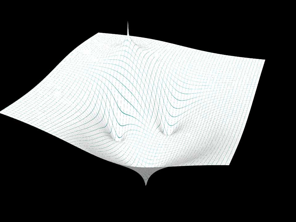
Waouh... big job ! I will study it closely.

My problem is not the geometry but its coloring.

My script generates a mesh (that I can save to use later). I get for
example this surface. it is a "3d" representation of the function
f(z) = (-z^3 + iz^2 + 1) / (z - 1 + i)^2

Without going into details and according with "Domain coloring", the
color of each point of f(z) is defined by its argument which is an angle
... and which corresponds to the hue.


--
Kurtz le pirate
Compagnie de la Banquise
Post a reply to this message
Attachments:
Download 'sample_low_res.jpg' (50 KB)
Preview of image 'sample_low_res.jpg'
|
|
| |
| |
|
|
|
|
| |
| |
|
|
"Bald Eagle" <cre### [at] netscapenet> wrote:

 > You're doing exactly the right things for your geometry.
 > Make sure you get the normals set correctly for the smooth_triangles,
 > so you get a nice smooth surface.
 >
 > Let me know if you're struggling there - I got it right a while back
 > after struggling with that myself - for the Bezier patch paper, IIRC.
 >

I just generate mesh with triangles.
No mesh2 and smooth_triangles. I don't know how to calculate the normals.


 > What I was trying to suggest in my first post was:
 >
 > "By using the texture_list it is possible to specify a texture per
 > triangle or even per vertex in the mesh. In the latter case the three
 > textures per triangle will be interpolated. To let POV-Ray know what
 > texture to apply to a triangle, the index of a texture is added to the
 > face_indices list, after the face index it belongs to.

Yes this feature seems to fit my needs.
The road is still long ...


Thanks Bill
Post a reply to this message
|
|
| |
| |
|
|
|
|
| |
| |
|
|
kurtz le pirate <kur### [at] gmailcom> wrote:

> My problem is not the geometry but its coloring.
>
> My script generates a mesh (that I can save to use later). I get for
> example this surface. it is a "3d" representation of the function
> f(z) = (-z^3 + iz^2 + 1) / (z - 1 + i)^2
>
> Without going into details and according with "Domain coloring", the
> color of each point of f(z) is defined by its argument which is an angle
> ... and which corresponds to the hue.


My problem seems to be less the coloring and more the geometry  :D

If I understand this correctly, you input a real, scalar angle, and get a
complex result out.  Then you plot the real part of f over the complex plane
described by z and the imaginary part of f?

Or is z actually x + iz, and your "3D" surface just a 3D slice of the 4D result
of your function - plotting the real or the imaginary part of f(z) over the x-z
plane?

And then you want to convert z to the H part of HSV and color <z, Re (f(z)), Im
(f(z))> according to that hue.

You are a masochist, a sadist, and a psychopath.
Much respect.  :D

I sent you an email - wondering if it arrived in inbox or spam.
Post a reply to this message
|
|
| |
| |
|
|
|
|
| |
| |
|
|
On 30/11/2021 03:51, Bald Eagle wrote:

>
> You are a masochist, a sadist, and a psychopath.
> Much respect.  :D
>
> I sent you an email - wondering if it arrived in inbox or spam.
>

In Inbox !


--
Kurtz le pirate
Compagnie de la Banquise
Post a reply to this message
|
|
| |
| |
|
|
|
|
| |
| |
|
|
kurtz le pirate <kur### [at] gmailcom> wrote:
>
>...
> My problem is not the geometry but its coloring.
>
> My script generates a mesh (that I can save to use later). I get for
> example this surface. it is a "3d" representation of the function
> f(z) = (-z^3 + iz^2 + 1) / (z - 1 + i)^2
>
> Without going into details and according with "Domain coloring", the
> color of each point of f(z) is defined by its argument which is an angle
> ... and which corresponds to the hue.

Hi Kurtz

Assuming your z is a complex variable with a real and imaginary part,
and that you plot the magnitude of your function as the height (along
POV-Ray's y-axis) over a complex plane with the real part along POV-
Ray's x-axis and the imaginary part along POV-Ray's z-axis then you
can use the argument (0 to 2*pi) of your function to choose a color
from a color map, like this:

// ===== 1 ======= 2 ======= 3 ======= 4 ======= 5 ======= 6 ======= 7

#version 3.7;

#declare Tau = 2*pi;

#declare YourMesh = mesh2 { ... }

#declare YourArgFn = function { ... };

#declare ColorWheel =
    color_map {
        [ 0/6 color rgb <1, 0, 0> ]
        [ 1/6 color rgb <1, 1, 0> ]
        [ 2/6 color rgb <0, 1, 0> ]
        [ 3/6 color rgb <0, 1, 1> ]
        [ 4/6 color rgb <0, 0, 1> ]
        [ 5/6 color rgb <1, 0, 1> ]
        [ 6/6 color rgb <1, 0, 0> ]
    }

object {
    YourMesh
    pigment {
        function { YourArgFn(x, 0, z)/Tau }
        color_map { ColorWheel }
    }
}

// ===== 1 ======= 2 ======= 3 ======= 4 ======= 5 ======= 6 ======= 7

--
Tor Olav
http://subcube.com
https://github.com/t-o-k
Post a reply to this message
|
|
| |
| |
|
|
|
|
| |
| |
|
|
"Tor Olav Kristensen" <tor### [at] TOBEREMOVEDgmailcom> wrote:
> kurtz le pirate <kur### [at] gmailcom> wrote:
> >
> >...
> > My problem is not the geometry but its coloring.
> >
> > My script generates a mesh (that I can save to use later). I get for
> > example this surface. it is a "3d" representation of the function
> > f(z) = (-z^3 + iz^2 + 1) / (z - 1 + i)^2
> >
> > Without going into details and according with "Domain coloring", the
> > color of each point of f(z) is defined by its argument which is an angle
> > ... and which corresponds to the hue.
>
> Hi Kurtz
>
> Assuming your z is a complex variable with a real and imaginary part,
> and that you plot the magnitude of your function as the height (along
> POV-Ray's y-axis) over a complex plane with the real part along POV-
> Ray's x-axis and the imaginary part along POV-Ray's z-axis then you
> can use the argument (0 to 2*pi) of your function to choose a color
> from a color map, like this:
>...

Btw.:
I recommend this video for those of you that are interested in such problems:

"The 5 ways to visualize complex functions | Essence of complex analysis #3"
https://www.youtube.com/watch?v=NtoIXhUgqSk

--
Tor Olav
http://subcube.com
https://github.com/t-o-k
Post a reply to this message
|
|
| |
| |
|
|
|
|
| |
| |
|
|
On 27/11/2021 18:00, Bald Eagle wrote:
> You're doing exactly the right things for your geometry.   Make sure
you get the
> normals set correctly for the smooth_triangles, so you get a nice smooth
> surface.
> Let me know if you're struggling there - I got it right a while back after
> struggling with that myself - for the Bezier patch paper, IIRC.

Yes, I would like to have information on the calculation of the normals.


> "By using the texture_list it is possible to specify a texture per
triangle or
> even per vertex in the mesh. In the latter case the three textures per
triangle
> will be interpolated. To let POV-Ray know what texture to apply to a
triangle,
> the index of a texture is added to the face_indices list, after the
face index
> it belongs to.
>
> http://www.povray.org/documentation/view/3.7.1/68/
>
> scroll down to:
>
> 1.3.2.2.3 A separate texture per triangle

Yes, separate texture per triangle with texture_list.
Seems perfect but not easy to do (for me at least).

But, looking at the previous page of the documentation i found a mesh
object with texture by triangle.
http://www.povray.org/documentation/view/3.7.1/67/

This solution seems to me easier to use


On 01/12/2021 02:34, Tor Olav Kristensen wrote:
> Assuming your z is a complex variable with a real and imaginary part,
> and that you plot the magnitude of your function as the height (along
> POV-Ray's y-axis) over a complex plane with the real part along POV-
> Ray's x-axis and the imaginary part along POV-Ray's z-axis then you
> can use the argument (0 to 2*pi) of your function to choose a color
> from a color map, like this:
>
> // ===== 1 ======= 2 ======= 3 ======= 4 ======= 5 ======= 6 ======= 7
>
> #version 3.7;
>
> #declare Tau = 2*pi;
>
> #declare YourMesh = mesh2 { ... }
>
> #declare YourArgFn = function { ... };
>

Yes of corse. Is an elegant solution to this problem.
It's the same thing that bugman123 use.
YourArgFn() ... I can't define and use this function correctly.

I will start with the solution found in doc 1.3.2.1 Mesh Object.
I'll keep you informed.


Thanks you for your help and suggestions.


--
Kurtz le pirate
Compagnie de la Banquise
Post a reply to this message
|
|
| |
| |
|
|
|
|
| |
|
|