|
|
|
|
|
|
| |
| |
|
|
|
|
| |
| |
|
|
I'm looking through the docs and see that vrotate *seems* to do what I'm
looking for; that is to have a vector A which is rotated by a vector B.

So this would mean that if I have two vectors, say the top and bottom of a
cyl, that I could, using vrotate, arbitrarily rotate the top of the cyl
while leaving the bottom in place?

If so, sweet, and can vrotation be used to determine the effect of vrotate?
Would vcross give the perpendicular axis needed in vrotation, if its inputs
were vector A and vector B from above?

I really should have started digging around in this program more fully many
years ago. :-|

ian
Post a reply to this message
|
|
| |
| |
|
|
|
|
| |
| |
|
|
"[GDS|Entropy]" <gds### [at] hotmail com> wrote in message
news:49af84d0$1@news.povray.org...
> I'm looking through the docs and see that vrotate *seems* to do what I'm
> looking for; that is to have a vector A which is rotated by a vector B.
>
It rotates vector A around the origin by the number of degrees specified by
vector B, returning a vector. It rotates by B.x followed by B.y then B.z.
Is that what you want to do?
> So this would mean that if I have two vectors, say the top and bottom of a
> cyl, that I could, using vrotate, arbitrarily rotate the top of the cyl
> while leaving the bottom in place?
>
You can use it to help you do that. You need to be a little careful because
you are talking about rotating one location vector around another location
vector and vrotate rotates around the origin, so you need to compensate for
that. You can use NewTop = vrotate(CylTop-CylBot,<30,0,0>)+CylBot; Then you
can use NewTop and CylBot to define a cylinder object.
> If so, sweet, and can vrotation be used to determine the effect of
> vrotate?
VRotation can indeed give you the angle between two direction vectors in
Radians. To use it with CylTop and CylBot you still need to work on the
difference between these positions to get a direction vector. Use VRotationD
if you want to work in degrees. These can't reveal the original 3 angles
used to rotate the vector in the first place.
> Would vcross give the perpendicular axis needed in vrotation, if its
> inputs were vector A and vector B from above?
You can use vcross or VPerp_To_Plane to give you an axis that's
perpendicular to two direction vectors (which you need for vrotation). You
wouldn't want to use A and B from above as input because A is a direction
vector, B is a vector containing 3 angles in degrees. You could use
(CylTop-CylBot) and (NewTop-CylBot) which provides two direction vectors.
Regards,
Chris B. com> wrote in message
news:49af84d0$1@news.povray.org...
> I'm looking through the docs and see that vrotate *seems* to do what I'm
> looking for; that is to have a vector A which is rotated by a vector B.
>
It rotates vector A around the origin by the number of degrees specified by
vector B, returning a vector. It rotates by B.x followed by B.y then B.z.
Is that what you want to do?
> So this would mean that if I have two vectors, say the top and bottom of a
> cyl, that I could, using vrotate, arbitrarily rotate the top of the cyl
> while leaving the bottom in place?
>
You can use it to help you do that. You need to be a little careful because
you are talking about rotating one location vector around another location
vector and vrotate rotates around the origin, so you need to compensate for
that. You can use NewTop = vrotate(CylTop-CylBot,<30,0,0>)+CylBot; Then you
can use NewTop and CylBot to define a cylinder object.
> If so, sweet, and can vrotation be used to determine the effect of
> vrotate?
VRotation can indeed give you the angle between two direction vectors in
Radians. To use it with CylTop and CylBot you still need to work on the
difference between these positions to get a direction vector. Use VRotationD
if you want to work in degrees. These can't reveal the original 3 angles
used to rotate the vector in the first place.
> Would vcross give the perpendicular axis needed in vrotation, if its
> inputs were vector A and vector B from above?
You can use vcross or VPerp_To_Plane to give you an axis that's
perpendicular to two direction vectors (which you need for vrotation). You
wouldn't want to use A and B from above as input because A is a direction
vector, B is a vector containing 3 angles in degrees. You could use
(CylTop-CylBot) and (NewTop-CylBot) which provides two direction vectors.
Regards,
Chris B.
Post a reply to this message
|
|
| |
| |
|
|
|
|
| |
| |
|
|
"[GDS|Entropy]" <gds### [at] hotmailcom> wrote:
> I'm looking through the docs and see that vrotate *seems* to do what I'm
> looking for; that is to have a vector A which is rotated by a vector B.
>
> So this would mean that if I have two vectors, say the top and bottom of a
> cyl, that I could, using vrotate, arbitrarily rotate the top of the cyl
> while leaving the bottom in place?
>
> If so, sweet, and can vrotation be used to determine the effect of vrotate?
> Would vcross give the perpendicular axis needed in vrotation, if its inputs
> were vector A and vector B from above?

Um... unfortunately, rotation stuff is quite complex, and I know neither whether
you got the docs right nor whether I get you right :}

First off, vrotate(A,B) does the same thing to vector A that an "object { O
rotate B }" does to the whole object O; i.e., B does not specify the axis to
rotate about, but rather a set of three consecutive rotations about the X, Y
and Z axes respectively.

For that reason, computing the dot product of A and B makes absolutely no sense.


Speaking of the VRotation macro and the perpendicular axis, the thing you should
input to - say - VRotation(A,B,C) - as C is c*VCross(A,B), where c is an
arbitrary float constant, of which only the size matters.

Actually, to my knowledge the only added value of VRotation over VAngle is that
while VAngle just gives you the angle between two vectors, VRotation will add
some direction information to this angle.


Maybe the best thing is you tell us what you actually want to do; vector stuff
involving rotations is quite a complex topic (as you can probably see from the
number of macros related to it).
Post a reply to this message
|
|
| |
| |
|
|
|
|
| |
| |
|
|
"clipka" <nomail@nomail> wrote in message
news:web.49afac96ed80e874f567c3de0@news.povray.org...
> Um... unfortunately, rotation stuff is quite complex, and I know neither
> whether
> you got the docs right

No, no...you are correct, I actually *do* have no idea what I'm talking
about. :-p
I tend to learn best by undertaking difficult tasks with basically no idea
what I am doing.
I know, I'm weird.. :-D

>nor whether I get you right :}

This is likely, as I am worse than horrible at explaining things that I
happen to be attempting, as I am sure you have realized by now.  :-)

>
> First off, vrotate(A,B) does the same thing to vector A that an "object
> { O
> rotate B }" does to the whole object O; i.e., B does not specify the axis
> to
> rotate about, but rather a set of three consecutive rotations about the X,
> Y
> and Z axes respectively.

I found this out by dicking around these last few hours.

> For that reason, computing the dot product of A and B makes absolutely no
> sense.
>
> Speaking of the VRotation macro and the perpendicular axis, the thing you
> should
> input to - say - VRotation(A,B,C) - as C is c*VCross(A,B), where c is an
> arbitrary float constant, of which only the size matters.

Ok, so I wasn't too awfully far from target there at least.

> Actually, to my knowledge the only added value of VRotation over VAngle is
> that
> while VAngle just gives you the angle between two vectors, VRotation will
> add
> some direction information to this angle.

This is potentially useful.

> Maybe the best thing is you tell us what you actually want to do; vector
> stuff
> involving rotations is quite a complex topic (as you can probably see from
> the
> number of macros related to it).

Ok.
I'm using the following macro (ye olde snowmacro core) to output relevant
vectors along with the surface normal:

#macro
GDSX_VectTestN(Array,normArray,ctr,vectorArray,testVector,testObject,Normal)
 #local vectorA = min_extent(testObject);
 #local vectorB = max_extent(testObject);
 #local i=0;
 #while (i<ctr)
  #if (((vectorArray[i].x <= vectorB.x) & (vectorArray[i].x >= vectorA.x)) &
((vectorArray[i].y <= vectorB.y) & (vectorArray[i].y >= vectorA.y)) &
((vectorArray[i].z <= vectorB.z) & (vectorArray[i].z >= vectorA.z)))
   #if (inside(testObject,vectorArray[i]))
    #declare Array[i] = trace(testObject,vectorArray[i],testVector,Normal);
    #declare normArray[i] = Normal;
   #end
  #end
 #set i=i+1;
 #end
#end

This works well, and I've tested the output with cyls, which give the effect
that I want, with the obvious exception that cyls make *terrible* moss.
Since I'm dealing with a moss object generated from a macro that
approximates Campylopus sp., which is obviously more complicated than a cyl,
I need to find a meaningful way to rotate the individual models according to
the surface normal to acheive any kind of meaningful effect.

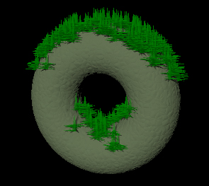
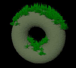
Right now I am stuck with the attached image, and I know you guys are just
about sick of that damned torus, but it renders fast and has a hole, so is
useful for testing trace based effects.
I also would like to use some kind of rotation within the actual moss object
macro every so often, as real moss isn't y+ straight (but the base of one
object must remain stationary while the top moves, I think NewTop =
vrotate(CylTop-CylBot,<30,0,0>)+CylBot; as proposed by Chris B might get
that at least in part, but requires the solution to the other problem to
use).

Thanks!
ian
Post a reply to this message
Attachments:
Download 'Moss.jpg' (46 KB)
Preview of image 'Moss.jpg'
|
|
| |
| |
|
|
|
|
| |
| |
|
|
"[GDS|Entropy]" <gds### [at] hotmailcom> wrote:
> This works well, and I've tested the output with cyls, which give the effect
> that I want, with the obvious exception that cyls make *terrible* moss.
> Since I'm dealing with a moss object generated from a macro that
> approximates Campylopus sp., which is obviously more complicated than a cyl,
> I need to find a meaningful way to rotate the individual models according to
> the surface normal to acheive any kind of meaningful effect.

Sounds like you want Reorient_Trans() in transforms.inc. Just put your small
moss component at the origin, aligned on the axis of your choice, then apply
this transform before translation.

http://www.povray.org/documentation/view/3.6.1/488/

Bill
Post a reply to this message
|
|
| |
| |
|
|
|
|
| |
| |
|
|
"Bill Pragnell" <bil### [at] hotmailcom> wrote in message
news:web.49afd147ed80e8746dd25f0b0@news.povray.org...
> Sounds like you want Reorient_Trans() in transforms.inc. Just put your
> small
> moss component at the origin, aligned on the axis of your choice, then
> apply
> this transform before translation.

Ok, so since my translation is the trace output and the vector I wish to
reorient towards is the normal, would I do this:

   object {
    mossFrond(5,6,<0,0,0>,0.125*0.5,frond)
    Reorient_Trans(mossVectArray[i],normVectArray[i])
    translate mossVectArray[i]
   }

That seems to get me close, but still some point straight up which should
not, and those which are pointing in a direction are aimed toward the
opposite of where they should be.

I'll post an image in p.b.i. (accidently posted one here earlier as I forgot
I was in p.g...need sleep...)

ian
Post a reply to this message
|
|
| |
| |
|
|
|
|
| |
| |
|
|
"[GDS|Entropy]" <gds### [at] hotmailcom> wrote:
> Ok, so since my translation is the trace output and the vector I wish to
> reorient towards is the normal, would I do this:
>
>    object {
>     mossFrond(5,6,<0,0,0>,0.125*0.5,frond)
>     Reorient_Trans(mossVectArray[i],normVectArray[i])
>     translate mossVectArray[i]
>    }

Almost. The first parameter should be the axis vector to be transformed, i.e.
your component object's up-direction. So, if mossFrond() is grown up the
y-axis, you need:

Reorient_Trans(y,normVectArray[i])

Bill
Post a reply to this message
|
|
| |
| |
|
|
|
|
| |
| |
|
|
"Bill Pragnell" <bil### [at] hotmailcom> wrote in message
news:web.49afdafded80e8746dd25f0b0@news.povray.org...
> Almost. The first parameter should be the axis vector to be transformed,
> i.e.
> your component object's up-direction. So, if mossFrond() is grown up the
> y-axis, you need:
>
> Reorient_Trans(y,normVectArray[i])

Oh jeebus... *smacks head*. That would explain a few things lol!
That works perfectly by the way. :)

So could this also work for orientation around a point, in a way that could
be used within the moss frond, versus just for its placement?

Thanks,
ian
Post a reply to this message
|
|
| |
| |
|
|
|
|
| |
| |
|
|
"[GDS|Entropy]" <gds### [at] hotmailcom> wrote:
> This works well, and I've tested the output with cyls, which give the effect
> that I want, with the obvious exception that cyls make *terrible* moss.
> Since I'm dealing with a moss object generated from a macro that
> approximates Campylopus sp., which is obviously more complicated than a cyl,
> I need to find a meaningful way to rotate the individual models according to
> the surface normal to acheive any kind of meaningful effect.

Ah, I see.

So what you're looking for is the B in object{O rotate B} so that whatever was
vertically in O is now parallel to a vector N (your normal).

Or, the transformation matrix M in object{O transform M} to get the same effect.

Try this:

  #include "transforms.inc"
  ...
  #declare M = Reorient_Trans(y, MyNormal)
  object{MyCampylopusSp transform { M } }

For better effect, you may want to use:

  object{
    MyCampylopusSp
    rotate y*rand(MyRand)*360
    transform { M }
  }

AFAIK this should do exactly the thing you want. I guess there's a clever
combination of V* macros that will give you the proper B for a "rotate B", but
nothing as easy and elegant as the Reorient_Trans macro.
Post a reply to this message
|
|
| |
| |
|
|
|
|
| |
| |
|
|
"clipka" <nomail@nomail> wrote:
>   #declare M = Reorient_Trans(y, MyNormal)

Just found an even simpler one:

    #declare M = Point_At_Trans(MyNormal)
Post a reply to this message
|
|
| |
| |
|
|
|
|
| |
| |
|
|
"[GDS|Entropy]" <gds### [at] hotmailcom> wrote:
> Oh jeebus... *smacks head*. That would explain a few things lol!
> That works perfectly by the way. :)

Goodgood. See also clipka's reply for rotating the frond first to give it a more
random look. :)

> So could this also work for orientation around a point, in a way that could
> be used within the moss frond, versus just for its placement?

I'm not sure what you mean... but, think of Reorient_Trans as a set of rotate
statements that aligns A to B. Using it to build an object and then using it to
align that object afterwards should be fine!

Bill
Post a reply to this message
|
|
| |
| |
|
|
|
|
| |
| |
|
|
"clipka" <nomail@nomail> wrote:
> "clipka" <nomail@nomail> wrote:
> >   #declare M = Reorient_Trans(y, MyNormal)
>
> Just found an even simpler one:
>
>     #declare M = Point_At_Trans(MyNormal)

Of course. Forgot about that. :-)

If you're doing lots of them, looks like using Point_At_Trans() could be a bit
quicker.
Post a reply to this message
|
|
| |
| |
|
|
|
|
| |
| |
|
|
My own experience with tracing using Point_At_Trans() shows some weird (well,
*unexpected*) results, having to do with how the traced-on objects are oddly
rotated 'around' the normals that trace finds. It's easy to see this by tracing
a plain sphere from a randomly-orbiting trace location, with the trace direction
pointing at the center of the sphere. For making the object to place at all
those traced points, construct a little CSG object (at the origin as usual)
that shows an obvious 'direction'--like two cylinders made into an upside-down
'L'. When these are traced on using Point_At_Trans(Norm)  they show up where
they are supposed to, but as diamond-shaped 'patches' where all the objects in
each patch have the same rotation around the objects' 'relative y' axis, with
each patch's orientation different by 90-degrees or so from the other patches
(if that makes any sense!)

I've done a fair amount of thinking about this, and it seems to me that the
problem--if there really *is* one--is that there's no way for Point_At_Trans to
know where left and right are, referenced to the sphere surface itself. Because
the normal at a point really has no 'rotation' component built in, to tell
Point_At_Trans what to do at each point. Perhaps there's some subtle code
missing from the macro, I don't know.

The same thing occurs when tracing a height_field and using the macro; the bumps
of the HF can be considered as the 'upper half' of the sphere example I've
given. (And tracing a HF can produce even more rotational strangeness when
using the found normals--having to do with the image_map resolution the HF is
made from, and *if* a trace 'ray' happens to hit a triangle vertex point or
near(?) it. From my own limited tests, it seems that the normal has a direction
of <0,1,0> or straight up.)

Luckily, when using a rather amorphous shape for the traced-on object--like a
blob--these rotation anomalies don't show themselves too badly.

Ken W.
Post a reply to this message
|
|
| |
| |
|
|
|
|
| |
| |
|
|
"Kenneth" <kdw### [at] earthlinknet> wrote:
> I've done a fair amount of thinking about this, and it seems to me that the
> problem--if there really *is* one--is that there's no way for Point_At_Trans to
> know where left and right are, referenced to the sphere surface itself. Because
> the normal at a point really has no 'rotation' component built in, to tell
> Point_At_Trans what to do at each point.

Yes, that's exactly the point. As a matter of fact, how would you *define* left
and right in such a context at all?

So the only constraint Point_At_Trans uses for choosing left and right is that
its computations don't go berserk (for instance, choosing left to be coincident
with up would obviously mess up things).

> Perhaps there's some subtle code missing from the macro, I don't know.

No, it's perfectly fine as it is. If you need more control over left/right
issues, you'll need to use a series of VCross operations instead.


> Luckily, when using a rather amorphous shape for the traced-on object--like a
> blob--these rotation anomalies don't show themselves too badly.

Even in such cases it is probably wise to do a random rotation about the y axis
first, to kill off any remaining subtle patterns due to orientation.
Post a reply to this message
|
|
| |
| |
|
|
|
|
| |
| |
|
|
"clipka" <nomail@nomail> wrote:

> > Perhaps there's some subtle code missing from the macro, I don't know.
>
> No, it's perfectly fine as it is. If you need more control over left/right
> issues, you'll need to use a series of VCross operations instead.

Ugh. VCross, vdot...my head spins.  I'm still having trouble wrapping my poor
little mind around the transform.inc stuff in general; just spent (another!)
hour or two poring over it all. I try mightily to use some of those macros in
my code, only to find that my understanding of their workings is just plain
wrong, or else I'm not setting them up correctly. Someday it all *will* infuse
my brain cells...

An example (which I'm trying to figure out at the moment): making my translated
camera rotate or 'roll' (like the 'rolling' of an airplane, if I have the
analogy correct), around the axis defined by/between the arbitrary camera
position and its look_at point. (So that the rolling axis is 'centered' in the
camera lens, so to speak.)  I *know* it should be simple to do, but right now
it's a mystery wrapped in an enigma.
>
> > Luckily, when using a rather amorphous shape for the traced-on object--like a
> > blob--these rotation anomalies don't show themselves too badly.
>
> Even in such cases it is probably wise to do a random rotation about the y axis
> first, to kill off any remaining subtle patterns due to orientation.

Good idea.

KW
Post a reply to this message
|
|
| |
| |
|
|
|
|
| |
| |
|
|
"Kenneth" <kdw### [at] earthlinknet> wrote:
> Ugh. VCross, vdot...my head spins.  I'm still having trouble wrapping my poor
> little mind around the transform.inc stuff in general; just spent (another!)
> hour or two poring over it all. I try mightily to use some of those macros in
> my code, only to find that my understanding of their workings is just plain
> wrong, or else I'm not setting them up correctly. Someday it all *will* infuse
> my brain cells...
>
> An example (which I'm trying to figure out at the moment): making my translated
> camera rotate or 'roll' (like the 'rolling' of an airplane, if I have the
> analogy correct), around the axis defined by/between the arbitrary camera
> position and its look_at point. (So that the rolling axis is 'centered' in the
> camera lens, so to speak.)  I *know* it should be simple to do, but right now
> it's a mystery wrapped in an enigma.

I know this feeling. Luckily, I have come to a point where, when I *do* take
time to think about it, I ultimately come up with something that does the job.
However, unless I really *need* to, I prefer not to bother my brains with these
things. It feels like I need to re-route half of my synapses each time :P

As a matter of fact, "rolling" some object is not so trivial as it may seem at
first, as the only rotational operations POV provides (including the macros in
"translations.h") are rotations about the main axes.

So here's how to do it:

- Calculate a transformation M that will get your object from its current
orientation to one that will align its axis of rotation to, say, z. This is the
trickiest part.

- Apply the following transofrmations:

    tramsform { M }
    rotate z*alpha
    transform { M inverse }

To get the transformation M, you need to first rotate the object about the y
axis to re-orient the intended axis of rotation to somewhere in the yz plane,
then rotate the object about the x axis to re-orient it to the z axis.

To find out how you need to rotate about the y axis, you have to imagine looking
at it from straight above, i.e. ignore the y components of the vector:

    #local yAngle = VRotation(<1,0,1>*myAxis, z, y);
    #local myAxis2 = VRotate(myAxis, y*yAngle);

Now that you know where your axis will end up after rotating about y, you can
find out how to re-orient it to match the z axis:

    #local xAngle = VRotation(myAxis2, x, z);
    #local M = transform {
      rotate y * yAngle
      rotate x * xAngle
    }


Some things to keep in mind when working with vectors and transformations:

- VDot and VCross are your friends. Get to know them, and find out how to make
best use of them.

- Quite a lot of tasks are a good deal easier if you consider a 2D projection of
the thing first, then deal with the third dimension separately.

- Watch out for extreme situations; e.g. the above math will fail if the axis
you intend to rotate about happens to be the y axis.
Post a reply to this message
|
|
| |
| |
|
|
|
|
| |
| |
|
|
"clipka" <nomail@nomail> wrote:

> As a matter of fact, "rolling" some object is not so trivial as it may seem at
> first, as the only rotational operations POV provides (including the macros in
> "translations.h") are rotations about the main axes.
>
> So here's how to do it:
>
> - Calculate a transformation M that will get your object from its current
> orientation to one that will align its axis of rotation to, say, z...

Hmm, I feel those synapses firing...

> To get the transformation M, you need to first rotate the object about the y
> axis to re-orient the intended axis of rotation to somewhere in the yz plane,
> then rotate the object about the x axis to re-orient it to the z axis.

I think I see smoke coming out of my ears...
>
> Now that you know where your axis will end up after rotating about y, you can
> find out how to re-orient it to match the z axis:
>

My hair's on fire!  :-p

In all seriousness, thanks tremendously much for the code, and for taking the
time to explain it.  I need to digest all this, and to re-think how I was
'looking' at the problem. What you've given me is certainly 100% more (at
least!) than what I knew before.
>
> - VDot and VCross are your friends. Get to know them, and find out how to make
> best use of them.

Yes, I need more POV-code-snippet friends.  As the saying goes, "You can't have
too many friends!" But sometimes they're hard to get to know...

> - Quite a lot of tasks are a good deal easier if you consider a 2D projection
> of the thing first, then deal with the third dimension separately.
>

That's good advice, and I'll keep it in mind.  OK, time for another marathon
thinking session!

KW
Post a reply to this message
|
|
| |
| |
|
|
|
|
| |
|
|