|
|
|
|
|
|
| |
| |
|
|
|
|
| |
| |
|
|
I suppose that my next logical question is:
the sor documentation states, "The intersection test with a SOR object involves
solving a cubic polynomial while the test with a lathe object requires to solve
a 6th order polynomial" ...
but upon reviewing the lathe documentation, one can choose between a variety of
different spline types.
So perhaps that needs some clarification / correction / expansion.
(I've also written a Newton-Raphson root solver, and so probably should
investigate the Sturmian root solver.)
- BW
Post a reply to this message
|
|
| |
| |
|
|
|
|
| |
| |
|
|
"Bald Eagle" <cre### [at] netscape net> wrote:
> So hopefully I'll be able to get the SDL to work tonight.
It took longer than i thought, because in order to make the f(h) equation match
the documentation, I had to flip everything upside down and backwards from the
way I did it in Excel. And I used arrays.
But it all works, which is what I needed to do.
With regard to POV 4.0, I see no reason why the number of points needs to be
specified, since the source can count the points when parsing the SDL.
There ought to be a way to specify the "tension" like in a proper Catmull-Rom
spline.
Anyway, here ya go.
- BW net> wrote:
> So hopefully I'll be able to get the SDL to work tonight.
It took longer than i thought, because in order to make the f(h) equation match
the documentation, I had to flip everything upside down and backwards from the
way I did it in Excel. And I used arrays.
But it all works, which is what I needed to do.
With regard to POV 4.0, I see no reason why the number of points needs to be
specified, since the source can count the points when parsing the SDL.
There ought to be a way to specify the "tension" like in a proper Catmull-Rom
spline.
Anyway, here ya go.
- BW
Post a reply to this message
Attachments:
Download 'surface of revolution documentation.png' (62 KB)
Preview of image 'surface of revolution documentation.png'

|
|
| |
| |
|
|
|
|
| |
| |
|
|
"jr" <cre### [at] gmailcom> wrote:
> having just read your follow-up, it seems that the interpolation "loose end"
> needs to be sorted.
So, I just wrote the whole thing from scratch, the way it seemed to me to work,
according to that last linked Wordpress page.
https://wiki.povray.org/content/File:RefImgCurvmath.png
Looks like it was made, or at least uploaded by Jim Holsenback.
> if then you can provide a (working) "worked example" and
> (brief ;-)) explanation, we can update that part of the documentation.
I can likely provide a "mathematical" or a code example - either as the vector *
matrix form, or as the intermediate result (A, B, C, & D).
There are some YT videos that seem to go over the topic, so perhaps I can either
use on of those, or dig up the original paper by Catmull and Rom to show the
derivation, and why the vector and matrix values are what they are.
In typical fashion, I can expand all that to simulate / demonstrate how that
curve gets wrapped around the axis to make the "sor" object (both
graphically/geometrically and mathematically), as well as render it as a
parametric {} and an isosurface {}. Easy enough to do that as a union of
triangle{}s, perhaps mesh {}, less likely mesh2{}.
I already edited the doc page in OpenOffice as a first rough draft, however it
may need revision after I at some point figure out exactly what's going on with
the lathe {} object.
As with all things, I'd like to see some level of clarity, completeness, and
comprehensiveness in our documentation. So, in my mind, I would like to see
POV-Ray serve as a repository of computer graphics education that clearly and
completely explains all of the historical and current concepts in computer
graphics, with references, working code, and of course eye-popping artistic
renders.
So perhaps we can make a list of all of the various different kinds of splines,
and see if we can't get as many of them implemented as is practical. I know
Jerome worked out Rational Bezier Splines a while back, and TOK has NURBS worked
out. Even though none of it is in source, it can be implemented via
macros/include files, and in a way, that's a better educational resource that
people can refer to.
* Because we need to attract more people here to spur further development *
- BW
P. S.
With regard to the "equations as images" that we have in ours docs, I'd like to
see some level of plain text version that can be copy/pasted. Or if there is
some way, perhaps we can have MathJax implemented so that we can have great
looking equations.
Post a reply to this message
|
|
| |
| |
|
|
|
|
| |
| |
|
|
This covers the basics,
https://www.cs.cmu.edu/~fp/courses/graphics/asst5/catmullRom.pdf
but Wikipedia shows that there are uniform, chordal, and centripetal forms as
well.
(granted for our present purposes, I think we are just using the uniform version
with a tension of 1.0 )
Post a reply to this message
|
|
| |
| |
|
|
|
|
| |
| |
|
|
hi,
"Bald Eagle" <cre### [at] netscapenet> wrote:
> "jr" <cre### [at] gmailcom> wrote:
> ...
> With regard to the "equations as images" that we have in ours docs, I'd like to
> see some level of plain text version that can be copy/pasted. Or if there is
> some way, perhaps we can have MathJax implemented so that we can have great
> looking equations.
I'll reply tomorrow (Sunday), via email, on topic. on the above, the wiki has a
math extension installed, perhaps that should enable you to write the equations
"in text" (see attached).
regards, jr.
Post a reply to this message
Attachments:
Download 'screenshot 2025-08-16 07.02.03.png' (34 KB)
Preview of image 'screenshot 2025-08-16 07.02.03.png'

|
|
| |
| |
|
|
|
|
| |
| |
|
|
"jr" <cre### [at] gmailcom> wrote:
> I'll reply tomorrow (Sunday), via email, on topic.
Well, before I go changing the documentation for POV-Ray, I'd like to point out
that currently I have only worked out some form of the Catmull-Rom spline that
seems to work in a predictable way.
I'm currently at the state where I'm looking at the source code in sor.cpp to
try and figure out if the 2 things match in some way.
https://github.com/POV-Ray/povray/blob/master/source/core/shape/sor.cpp
1. The source uses the x and y values of the control points separately in the
terms of the equations used to solve for the coefficients. I do not.
2. The source uses powers of the control point y values in the matrix, whereas I
do not.
3. The source performs a matrix inversion before calculating the coefficients.
No idea why, or what that does (yet).
4. Then there are other adjustments after that,
c[0] = 3.0 * A;
c[1] = 2.0 * B;
c[2] = C;
5. and then they somehow need to "solve a polynomial" - presumably to find a
root.
n = Solve_Polynomial(2, c, r, false, 0.0, stats);
6. then this n value is used as the iterator in the interpolation
while (n--)
{
if ((r[n] >= y[0]) && (r[n] <= y[1]))
{
x[n] = sqrt(r[n] * (r[n] * (r[n] * A + B) + C) + D);
}
}
Which all seems bewilderingly complex to me, but seems to jive with current
documentation.
HOW that all works is currently beyond me.
It's just a giant big black box.
Somewhere around 2000, it seemed to be beyond Warp as well.
I have some thing to do today and tomorrow, but Maybe I can spin my version
around the y-axis and compare it the actual sor object and see if they're even
close.
- BW
Post a reply to this message
|
|
| |
| |
|
|
|
|
| |
| |
|
|
At the moment, everything is looking to more or less ok, there probably only
needs to be a minor amount of clarification and explanation to make the
documentation sufficiently user-friendly.
I added some comments to the source code for sor.cpp
and hopefully I can make a little more progress on comparing my own version
written from scratch to what's going on in source.
There are normal, chordal, and centripetal forms.
I suspect mine is the normal form, and the one in source is centripetal.
(I will need to check source against the following, which I stumbled upon)
https://splines.readthedocs.io/en/latest/euclidean/catmull-rom-properties.html
So the first thing we need to do is set up our system of equations that relates
a cubic interpolation between the START (P1) and END (P2) points of the spline
to the constraints for the data, namely that the spline has to pass _through_
the endpoints, and the tangents at the endpoints for the spline segments are
defined using the additional spline points P0 and P3.
Following along with the comments that summarize the matrix values, it will be
fairly easy to match this up with what is going on in this video:
https://www.youtube.com/watch?v=DLsqkWV6Cag
/* Use cubic interpolation. */
k[0] = P[i+1][X] * P[i+1][X]; // P1.x^2, actual spline start
k[1] = P[i+2][X] * P[i+2][X]; // P2.x^2, actual spline end
k[2] = (P[i+2][X] - P[i][X]) / (P[i+2][Y] - P[i][Y]); // df/dt at
spline start
k[3] = (P[i+3][X] - P[i+1][X]) / (P[i+3][Y] - P[i+1][Y]); // df/dt at
spline end (tangent)
k[2] *= 2.0 * P[i+1][X]; // = 2 P1.x * (P2.x - P0.x)
----------------------
(P2.y - P0.y)
k[3] *= 2.0 * P[i+2][X]; // = 2 P2.x * (P3.x - P1.x)
----------------------
(P3.y - P1.y)
w = P[i+1][Y];
Mat[0][0] = w * w * w; // P1.y^3
Mat[0][1] = w * w; // P1.y^2
Mat[0][2] = w; // P1.y
Mat[0][3] = 1.0; // 1
Mat[2][0] = 3.0 * w * w; // 3*P1.y^2
Mat[2][1] = 2.0 * w; // 2*P1.y
Mat[2][2] = 1.0; // 1
Mat[2][3] = 0.0; // 0
w = P[i+2][Y];
Mat[1][0] = w * w * w; // P2.y^3
Mat[1][1] = w * w; // P2.y^2
Mat[1][2] = w; // P2.y
Mat[1][3] = 1.0; // 1
Mat[3][0] = 3.0 * w * w; // 3*P2.y^2
Mat[3][1] = 2.0 * w; // 2*P2.y
Mat[3][2] = 1.0; // 1
Mat[3][3] = 0.0; // 0
-------------------------------------------------------------------------
One can solve a system of linear equations in a matrix using a number of
different methods.
The source uses the method of finding the matrix inverse, and then multiplying
both sides of the matrix equation by the matrix inverse.
(This is where the over-brief equation in the docs is confusing, without any
other context)
-------------------------------------------------------------------------
// Now we find the matrix inverse so that we can solve for the coefficients
/*
ax = b
(1/a)*ax = (1/a)*b
(a^-1)ax = (a^-1)b
(a^-1)*x = 1, so
x = (a^-1) b
*/
MInvers(Mat, Mat); // in math/matrix.cpp
// Once we have the matrix inverse, we take the data constraints and the matrix
inverse and
// multiply them to calculate the coefficients.
/* Calculate coefficients of cubic patch. */
// k[] is the column vector of the constraints
// and Mat[] is the *matrix_inverse* M
// so multiplying together equals the column vector of the coefficients
A = k[0] * Mat[0][0] + k[1] * Mat[0][1] + k[2] * Mat[0][2] + k[3] *
Mat[0][3];
B = k[0] * Mat[1][0] + k[1] * Mat[1][1] + k[2] * Mat[1][2] + k[3] *
Mat[1][3];
C = k[0] * Mat[2][0] + k[1] * Mat[2][1] + k[2] * Mat[2][2] + k[3] *
Mat[2][3];
D = k[0] * Mat[3][0] + k[1] * Mat[3][1] + k[2] * Mat[3][2] + k[3] *
Mat[3][3];
I still feel like there should be some minus signs in there to make the
interpolation work - but maybe those pop out the other side of the MInvers () .
.. . I'll have to write that out in SDL and run it to find out.
I also don't quite understand why we need to take the square root of the result
in line 1082
x[n] = sqrt(r[n] * (r[n] * (r[n] * A + B) + C) + D);
to get the interpolated spline values, but perhaps that may become clear as I
find more bits of time here and the to properly focus on this.
Just wanted to issue a progress report. :)
- BE
Post a reply to this message
|
|
| |
| |
|
|
|
|
| |
| |
|
|
"Bald Eagle" <cre### [at] netscapenet> wrote:
> I still feel like there should be some minus signs in there to make the
> interpolation work - but maybe those pop out the other side of the MInvers () .
> .. . I'll have to write that out in SDL and run it to find out.
Sent values of A-D for each segment to the debug stream, and there are
definitely minus signs.
> I also don't quite understand why we need to take the square root of the result
> in line 1082
> x[n] = sqrt(r[n] * (r[n] * (r[n] * A + B) + C) + D);
> to get the interpolated spline values, but perhaps that may become clear as I
> find more bits of time here and the to properly focus on this.
This apparently has to do with the value of "alpha" in the interpolation, with 0
being Uniform, 1/2 being Centripetal, and 1 being Chordal.
I'm not really sure where "r" comes from in the source, or how that while loop
interpolates the spline, but I just ignored all of that, and things worked out
anyway. :D
After fixing some boneheaded visualization bugs, the math seemed to be working
out with the spline, so I took my SDL version of the SOR spline and used the X
value (minus the minor radius) as the major radius of a torus, and "plotted" a
torus at each interpolation point. (RED)
Seems to overlay the sor {} object (BLUE) very closely. Errors are probably due
to my janky simulation method, and coincident surfaces.
I'll try to work out the details as I write things up, and I'll probably make a
parametric {} and isosurface {} object to further test how well things match up.
- BE
Post a reply to this message
Attachments:
Download 'surface of revolution documentation.png' (255 KB)
Preview of image 'surface of revolution documentation.png'

|
|
| |
| |
|
|
|
|
| |
| |
|
|
"Bald Eagle" <cre### [at] netscapenet> wrote:
> ... I'll probably make a
> parametric {} and isosurface {} object to further test how well things match up.
So this is the isosurface version, overlaid on the POV-Ray sor {} object
object {SOR scale 0.999999}
(It's actually one isosurface for every individual segment of the CR spline)
If I scale to 5 nines, I get a LOT more coincident surface artefacts, so I'd say
that everything is working very nicely.
I would still like to see that original 1989 paper, and perhaps I can work out
the square root thing with some level of rigor.
I'm pretty happy with what I've got, and will get working on some sort of
write-up.
If anyone has any questions, or would like to see a specific type of render,
animation, or mathematical derivation, just let me know, so I can include that.
- BE
Post a reply to this message
Attachments:
Download 'surface of revolution documentation.png' (80 KB)
Preview of image 'surface of revolution documentation.png'

|
|
| |
| |
|
|
|
|
| |
| |
|
|
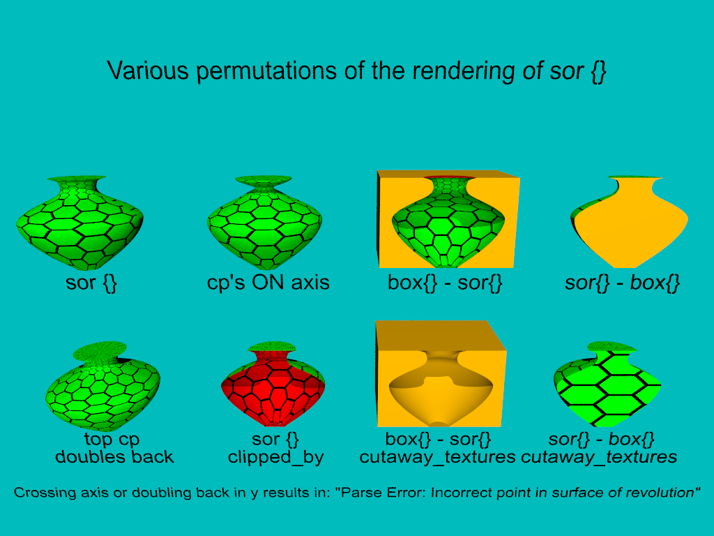
So, in the course of making some documentation renders, it became apparent that
there were a few things that were puzzling, needed to be sorted out, and some of
that was related to the behaviour of other keywords.
The following is a summary:
sor {} can have control points ON the axis, just not crossing it.
Else you get a "Parse Error: Incorrect point in surface of revolution"
I believe this is hard-coded behaviour in the source algorithm.
If I were to edit the source, it would allow the first and last control points
to cross the axis, since those points only exist to calculate the tangent
direction.
I do recall discussing this briefly in a thread with clipka and suggesting to
use abs {} somewhere in the algorithm, but I'd have to familiarize myself more
deeply with the specifics of what is going on numerically.
When using the sor {] object as the "cutter" in a difference {}, I unexpectedly
got some interior_texture {} showing in the result. Strangely enough, when i use
sor {open} the interior_texture {} is NOT visible, and I only see the surface
texture {}
When cutting away from the sor {}, I see the expected result, though I haven't
pursued this to see what more complicated geometry / CSG yields.
According to the sor {} tutorial in the wiki:
https://wiki.povray.org/content/Documentation:Tutorial_Section_3#Surface_of_Revolution_Object
"First and last point from the list are used to determine slope at beginning and
end of curve and can be defined for any height."
However, I find that to not be the case.
Swapping the first and last control points causes a
"Parse Error: Incorrect point in surface of revolution"
But if I only set the LAST control point y value to zero, technically making the
spline double-back in the y-direction, everything works fine.
and finally on to what sparked this whole investigation off:
I wanted to make a render comparing sor{} with sor {open}, but I had a devil of
a time slicing the vase in half and seeing the interior.
jr managed to achieve the desired result using clipped_by
As shown, when I use cutaway_textures, I DON'T see the expected
interior_texture, but the surface texture {}. And when I use sor {open}, I do
not see a hollow infinitely thin surface, I get a solid object sliced in half.
So, I would say that there are problems with the sor {} caps, possibly with the
normal vector.
As shown in the bottom left, when I slice the sor {open} in half with a box, I
get an apparently solid object. This is of course counterintuitive to what the
user expects, even though the documentation cautions that the open version might
yield unexpected results when used in CSG. I would probably classify this
result as sufficiently unexpected as to warrant its classification as a bug, or
for an extended warning with the clipped_by solution to be added to the
documentation.
Futhermore, if the documentation implies that a sor is solid - just look at the
CSG results of difference {} - then clipped_by ought to give me what I'm seeing
as difference {} only with the interior_texture {} properly displayed.
Other things I notice are that there is some noisy "cruft" at the base of the
clipped_by object. I also see some of that at the bottom of the difference{}s.
The texture is a tiling with a color_map, and is uv_mapped onto the surface(s).
As you can see on the right side of the object, the pattern does not line up
properly at the edges. In the model below that, "top cp doubles back", I
changed the scaling of the tiling to an even number, and it now lines up.
I recall reading about properly scaling patterns so that make them fit, and that
of course employed the use of pi or tau to calculate the proper scaling. This
might be a worthwhile keyword to implement for uv-mapping, perhaps some sort of
"scaling warp". Likely to be pattern and direction dependent.
All objects are rendered with sturm.
Enjoy & Discuss.
- BE
Post a reply to this message
Attachments:
Download 'sor permutations.png' (130 KB)
Preview of image 'sor permutations.png'

|
|
| |
| |
|
|
|
|
| |
|
|