 |
 |
|
 |
|
 |
|  |
|  |
|
 |
|
 |
|  |
|  |
|
 |
"Bald Eagle" <cre### [at] netscape net> wrote:
> "Kenneth" <kdw### [at] gmail net> wrote:
> "Kenneth" <kdw### [at] gmail com> wrote:
>
> > ... but there's possibly *some* kind of problem (maybe 'problem'
> > is not the right word) for how trace creates its normal in the first
> > place. But I haven't exactly narrowed the problem down to trace itself;
> > it may be in how the normal is being 'processed' by other POV-ray tools..
> >
>
> POV-Ray "measures" the normal of the surface that the ray intersects.
> I'm pretty sure that there's no problem there.
>
> Clearly understanding what those other macros actually do is probably
> where the problem lies.
>
Yeah, I think you're right on both counts. For some strange reason, I've always
had a half-baked belief that trace's normal (or *any* normal) has a preferred
'handedness' when it comes to applying an object along that normal... meaning,
the normal ITSELF might somehow be *rotating* the object to a new orientation,
depending on which direction the normal faces into the x/y/z universe. But
that's silly: a normal is *just a vector direction*. And I have to finally
dispel my mythical thinking. ;-) Thanks for waking up my tired ol' brain.
The object rotational problems I see when using the Point_At_Trans and
Reorient_Trans macros are specific to those tools, I agree. I've tried mightily
to 'correct' the resulting 'unexpected' object rotations (which DO result from
the normal's direction into space), but it's all quite mathematically
complicated.
Try tracing a simple sphere from random directions with thousands of greeble
objects applied, while using the found normals and those alignment macros to
place them, and you'll see what I mean.
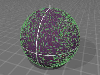
Here's an example using the Point_At_Trans macro, applying typical pre-made
objects. Note the delineated 'diamond' rotational patches. com> wrote:
>
> > ... but there's possibly *some* kind of problem (maybe 'problem'
> > is not the right word) for how trace creates its normal in the first
> > place. But I haven't exactly narrowed the problem down to trace itself;
> > it may be in how the normal is being 'processed' by other POV-ray tools..
> >
>
> POV-Ray "measures" the normal of the surface that the ray intersects.
> I'm pretty sure that there's no problem there.
>
> Clearly understanding what those other macros actually do is probably
> where the problem lies.
>
Yeah, I think you're right on both counts. For some strange reason, I've always
had a half-baked belief that trace's normal (or *any* normal) has a preferred
'handedness' when it comes to applying an object along that normal... meaning,
the normal ITSELF might somehow be *rotating* the object to a new orientation,
depending on which direction the normal faces into the x/y/z universe. But
that's silly: a normal is *just a vector direction*. And I have to finally
dispel my mythical thinking. ;-) Thanks for waking up my tired ol' brain.
The object rotational problems I see when using the Point_At_Trans and
Reorient_Trans macros are specific to those tools, I agree. I've tried mightily
to 'correct' the resulting 'unexpected' object rotations (which DO result from
the normal's direction into space), but it's all quite mathematically
complicated.
Try tracing a simple sphere from random directions with thousands of greeble
objects applied, while using the found normals and those alignment macros to
place them, and you'll see what I mean.
Here's an example using the Point_At_Trans macro, applying typical pre-made
objects. Note the delineated 'diamond' rotational patches.
Post a reply to this message
Attachments:
Download 'traced_sphere_using_point_at_trans.jpg' (118 KB)
Preview of image 'traced_sphere_using_point_at_trans.jpg'

|
 |
|  |
|  |
|
 |
|
 |
|  |
|  |
|
 |
"Kenneth" <kdw### [at] gmail com> wrote:
> The object rotational problems I see when using the Point_At_Trans and
> Reorient_Trans macros are specific to those tools, I agree. I've tried mightily
> to 'correct' the resulting 'unexpected' object rotations (which DO result from
> the normal's direction into space), but it's all quite mathematically
> complicated.
It's always complicated when we're using black-box macros and shooting in the
dark.
> Try tracing a simple sphere from random directions with thousands of greeble
> objects applied, while using the found normals and those alignment macros to
> place them, and you'll see what I mean.
Well, I tend to do things like that "by hand" using macros that I write deriving
everything from first-principles.
> Here's an example using the Point_At_Trans macro, applying typical pre-made
> objects. Note the delineated 'diamond' rotational patches.
They're not "diamonds" - they're triangles.
So let's peek into tranforms.inc:
// Similar to Reorient_Trans(), points y axis along Axis.
#macro Point_At_Trans (YAxis)
// this is just a simple vector normalization. No mystery.
#local Y = vnormalize (YAxis);
// this is a macro - I can't tell if it's a source-code thing, or a
math.inc thing. But here's where I think is what causes what you see. (* see
below)
#local X = VPerp_To_Vector (Y);
// vcross returns 0 when vectors are (anti-)parallel, and +/-1 when
perpendicular
#local Z = vcross (X, Y);
// As far as I can see, shear trans just applies a straightforward
transformation matrix, using x, y, and z. And all those three vectors are
perpendicular, which is merely what all of the above code does. And so the
whole object gets oriented to a "new y vector"
Shear_Trans (X, Y, Z)
#end
* So, let's take a look at VPerp_To_Vector()
It takes a single argument. Given a vector, find a vector perpendicular to it.
Which is ridiculous, given that I can spin a T-square around, and come up with
literally an infinite number of parallel vectors.
So let's take a look at what the macro specifically DOES.
Peeking into math.inc:
// Returns a vector perpendicular to V
// Author: Tor Olav Kristensen
#macro VPerp_To_Vector(v0)
#if (vlength(v0) = 0)
#local vN = <0, 0, 0>;
// Sanity check. If you give it a/the zero vector, send it right back.
#else
#local Dm = min(abs(v0.x), abs(v0.y), abs(v0.z));
// And here's where we get the three-fold symmetry. Find the smallest component
of the supplied vector. This drives the rest of the macro results, which
computes the vector cross-product between your "new y vector" (the surface
normal), and the cardinal axis that it is "farthest away from". What's the
center point of that 3-pronged choice tree? The center of the triangle(s) in
your render.
Take a cardinal axis and start generating results from this macro as you rotate
it. Eventually you will rotate it so far that a DIFFERENT cardinal axis will be
chosen by the macro to calculate the vector cross-product with. And there are
only 3 axes, so you get triangular wedges of each octant of your sphere.
#if (abs(v0.z) = Dm)
#local vN = vnormalize(vcross(v0, z));
#else
#if (abs(v0.y) = Dm)
#local vN = vnormalize(vcross(v0, y));
#else
#local vN = vnormalize(vcross(v0, x));
#end
#end
#end
vN // <--- returns one of three results
#end
So, now that we see where the problem is and why, we can formulate any number of
solutions.
The first and easiest is just write a new macro where you either use only one
dedicated axis as your second vector cross-product vector, or one where you can
choose which vector you want. Or generate a random vector.
Second, you could take a look at which cardinal vector was used, and further
rotate your greeble based on that, to "correct" its orientation.
Maybe there are other options as well.
Maybe the POV-Ray light_source will shine its benevolent rays upon us, and TOK
will chime in with something elegant and brilliant. :D com> wrote:
> The object rotational problems I see when using the Point_At_Trans and
> Reorient_Trans macros are specific to those tools, I agree. I've tried mightily
> to 'correct' the resulting 'unexpected' object rotations (which DO result from
> the normal's direction into space), but it's all quite mathematically
> complicated.
It's always complicated when we're using black-box macros and shooting in the
dark.
> Try tracing a simple sphere from random directions with thousands of greeble
> objects applied, while using the found normals and those alignment macros to
> place them, and you'll see what I mean.
Well, I tend to do things like that "by hand" using macros that I write deriving
everything from first-principles.
> Here's an example using the Point_At_Trans macro, applying typical pre-made
> objects. Note the delineated 'diamond' rotational patches.
They're not "diamonds" - they're triangles.
So let's peek into tranforms.inc:
// Similar to Reorient_Trans(), points y axis along Axis.
#macro Point_At_Trans (YAxis)
// this is just a simple vector normalization. No mystery.
#local Y = vnormalize (YAxis);
// this is a macro - I can't tell if it's a source-code thing, or a
math.inc thing. But here's where I think is what causes what you see. (* see
below)
#local X = VPerp_To_Vector (Y);
// vcross returns 0 when vectors are (anti-)parallel, and +/-1 when
perpendicular
#local Z = vcross (X, Y);
// As far as I can see, shear trans just applies a straightforward
transformation matrix, using x, y, and z. And all those three vectors are
perpendicular, which is merely what all of the above code does. And so the
whole object gets oriented to a "new y vector"
Shear_Trans (X, Y, Z)
#end
* So, let's take a look at VPerp_To_Vector()
It takes a single argument. Given a vector, find a vector perpendicular to it.
Which is ridiculous, given that I can spin a T-square around, and come up with
literally an infinite number of parallel vectors.
So let's take a look at what the macro specifically DOES.
Peeking into math.inc:
// Returns a vector perpendicular to V
// Author: Tor Olav Kristensen
#macro VPerp_To_Vector(v0)
#if (vlength(v0) = 0)
#local vN = <0, 0, 0>;
// Sanity check. If you give it a/the zero vector, send it right back.
#else
#local Dm = min(abs(v0.x), abs(v0.y), abs(v0.z));
// And here's where we get the three-fold symmetry. Find the smallest component
of the supplied vector. This drives the rest of the macro results, which
computes the vector cross-product between your "new y vector" (the surface
normal), and the cardinal axis that it is "farthest away from". What's the
center point of that 3-pronged choice tree? The center of the triangle(s) in
your render.
Take a cardinal axis and start generating results from this macro as you rotate
it. Eventually you will rotate it so far that a DIFFERENT cardinal axis will be
chosen by the macro to calculate the vector cross-product with. And there are
only 3 axes, so you get triangular wedges of each octant of your sphere.
#if (abs(v0.z) = Dm)
#local vN = vnormalize(vcross(v0, z));
#else
#if (abs(v0.y) = Dm)
#local vN = vnormalize(vcross(v0, y));
#else
#local vN = vnormalize(vcross(v0, x));
#end
#end
#end
vN // <--- returns one of three results
#end
So, now that we see where the problem is and why, we can formulate any number of
solutions.
The first and easiest is just write a new macro where you either use only one
dedicated axis as your second vector cross-product vector, or one where you can
choose which vector you want. Or generate a random vector.
Second, you could take a look at which cardinal vector was used, and further
rotate your greeble based on that, to "correct" its orientation.
Maybe there are other options as well.
Maybe the POV-Ray light_source will shine its benevolent rays upon us, and TOK
will chime in with something elegant and brilliant. :D
Post a reply to this message
|
 |
|  |
|  |
|
 |
|
 |
|  |
|  |
|
 |
So, following the logic from:
http://news.povray.org/povray.general/thread/%3Cweb.410eba6fcd20604ecbae57f30@news.povray.org%3E/?ttop=300207&toff=1950
just include transforms.inc, THEN redefine the "offending" macro:
#macro VPerp_To_Vector (v0)
#if (vlength(v0) = 0)
#local vN = <0, 0, 0>;
#else
#local x_point = vcross (x, v0);
#if (vlength (x_point) = 0)
#local x_point = vcross(y, v0); // if x was parallel to v0, try y instead
#end
#if (vlength (x_point) = 0)
#local x_point = vcross(z, v0); // if x was parallel to v0, try y instead
#end
#end
#local vN = x_point;
vN
#end
Then generate your random points, find your intersection point and normal
vector,
#declare Normal = <0, 0, 0>;
#local iPoint = TracePointA (Sphere, Loc, Normal);
object {Greeble Point_At_Trans (Normal) translate iPoint}
and you should be good.
Post a reply to this message
Attachments:
Download 'greeble_placement.png' (196 KB)
Preview of image 'greeble_placement.png'

|
 |
|  |
|  |
|
 |
|
 |
|  |
|  |
|
 |
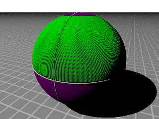
So I made some "greebles", chosen and pigmented at random, and placed with trace
() and VRand_On_Sphere()
Post a reply to this message
Attachments:
Download 'greeble_placement.png' (345 KB)
Preview of image 'greeble_placement.png'

|
 |
|  |
|  |
|
 |
|
 |
|  |
|  |
|
 |
"Bald Eagle" <cre### [at] netscape net> wrote:
> So, following the logic from:
(I think this is the link you meant; it got garbled in translation)...
http://news.povray.org/povray.general/thread/%3Cweb.410eba6fcd20604ecbae57f30@news.povray.org%3E/?ttop=300207&toff=1950
>
> just include transforms.inc, THEN redefine the "offending" macro:
> [snip]
> and you should be good.
Wow. That is... magical to me (to you, it is probably business as usual, ha.)
You have solved a persistent problem that I've been trying to figure out for at
least 15 years...but without your truly excellent knowledge of vcross et al.
Maybe others here find it equally as fascinating. Thanks a bunch for dissecting
those macros, and for really pinning down the essential elements of WHY they
produce the results they do.
This topic (and your solution) deserves a post of its own. Rather than comment
any further, I would like to take the pertinent comments and images here and and
re-post them under a new heading; give me a little time to do so. IMO, your
solution would be of great help to others who use trace. net> wrote:
> So, following the logic from:
(I think this is the link you meant; it got garbled in translation)...
http://news.povray.org/povray.general/thread/%3Cweb.410eba6fcd20604ecbae57f30@news.povray.org%3E/?ttop=300207&toff=1950
>
> just include transforms.inc, THEN redefine the "offending" macro:
> [snip]
> and you should be good.
Wow. That is... magical to me (to you, it is probably business as usual, ha.)
You have solved a persistent problem that I've been trying to figure out for at
least 15 years...but without your truly excellent knowledge of vcross et al.
Maybe others here find it equally as fascinating. Thanks a bunch for dissecting
those macros, and for really pinning down the essential elements of WHY they
produce the results they do.
This topic (and your solution) deserves a post of its own. Rather than comment
any further, I would like to take the pertinent comments and images here and and
re-post them under a new heading; give me a little time to do so. IMO, your
solution would be of great help to others who use trace.
Post a reply to this message
|
 |
|  |
|  |
|
 |
|
 |
|  |
|  |
|
 |
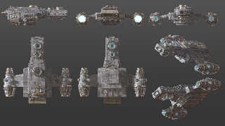
Here's an update on my spaceship model and what's probably close to final
texturing. I've played around with some outer space lighting (i.e., dark) in
various test scenes and what I have here works pretty well in the setups I've
tried so far.
Post a reply to this message
Attachments:
Download 'spaceshipmultiviewtextured.jpg' (548 KB)
Preview of image 'spaceshipmultiviewtextured.jpg'

|
 |
|  |
|  |
|
 |
|
 |
|  |
|  |
|
 |
"Robert McGregor" <rob### [at] mcgregorfineart com> wrote:
> Here's an update on my spaceship model and what's probably close to final
> texturing. I've played around with some outer space lighting (i.e., dark) in
> various test scenes and what I have here works pretty well in the setups I've
> tried so far.
Well - damn. You prettied that sucker up very nicely :)
Are the greebles a layered texture (looks kinda like cells as the base), or a
texture with a normal for the "outlines" of the rectangles...? com> wrote:
> Here's an update on my spaceship model and what's probably close to final
> texturing. I've played around with some outer space lighting (i.e., dark) in
> various test scenes and what I have here works pretty well in the setups I've
> tried so far.
Well - damn. You prettied that sucker up very nicely :)
Are the greebles a layered texture (looks kinda like cells as the base), or a
texture with a normal for the "outlines" of the rectangles...?
Post a reply to this message
|
 |
|  |
|  |
|
 |
|
 |
|  |
|  |
|
 |
"Bald Eagle" <cre### [at] netscape net> wrote:
> Well - damn. You prettied that sucker up very nicely :)
Thank you :)
> Are the greebles a layered texture (looks kinda like cells as the base), or a
> texture with a normal for the "outlines" of the rectangles...?
It's a couple of macros that build layered textures using a grayscale image map
pigment function as an image pattern to give variable reflection based on map
color. This serves as the bump map and underlying pigment layer too, but with
other grungy stuff averaged on top, something like:
#macro T_Ship1(vecScale, useUV)
function { fn_P_Hull(x,y,z).gray }
texture_map {
[0
#if (useUV) uv_mapping #end
pigment {
average
pigment_map {
[2 rgb 1]
[2 P_Metal01]
[2 P_Metal02]
[4 P_Hull]
}
}
normal { N_Hull }
finish { diffuse 0.65 }
scale vecScale
]
[1
#if (useUV) uv_mapping #end
pigment{
average
pigment_map{
[2 rgb 1]
[2 P_Metal01]
[2 P_Metal02]
[4 P_Hull]
}
}
normal { N_Hull }
finish {
diffuse 0.85
reflection { 0.1, 0.5 fresnel on }
conserve_energy
}
scale vecScale
]
}
#end
object { shipPart texture { T_Ship1(15, true) } interior { ior 2 } }
The main greebles image map is just a bunch of random rectangles of different
size, scales, and shades of gray from almost white through almost black. net> wrote:
> Well - damn. You prettied that sucker up very nicely :)
Thank you :)
> Are the greebles a layered texture (looks kinda like cells as the base), or a
> texture with a normal for the "outlines" of the rectangles...?
It's a couple of macros that build layered textures using a grayscale image map
pigment function as an image pattern to give variable reflection based on map
color. This serves as the bump map and underlying pigment layer too, but with
other grungy stuff averaged on top, something like:
#macro T_Ship1(vecScale, useUV)
function { fn_P_Hull(x,y,z).gray }
texture_map {
[0
#if (useUV) uv_mapping #end
pigment {
average
pigment_map {
[2 rgb 1]
[2 P_Metal01]
[2 P_Metal02]
[4 P_Hull]
}
}
normal { N_Hull }
finish { diffuse 0.65 }
scale vecScale
]
[1
#if (useUV) uv_mapping #end
pigment{
average
pigment_map{
[2 rgb 1]
[2 P_Metal01]
[2 P_Metal02]
[4 P_Hull]
}
}
normal { N_Hull }
finish {
diffuse 0.85
reflection { 0.1, 0.5 fresnel on }
conserve_energy
}
scale vecScale
]
}
#end
object { shipPart texture { T_Ship1(15, true) } interior { ior 2 } }
The main greebles image map is just a bunch of random rectangles of different
size, scales, and shades of gray from almost white through almost black.
Post a reply to this message
|
 |
|  |
|  |
|
 |
|
 |
|  |
|  |
|
 |
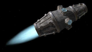
Here's a test of the engine "exhaust" media that I've been working on. I added
some clock-based turbulence and rotation so it will flicker somewhat from frame
to frame when animated, hopefully like flames. To smooth out the overall effect
for this image I averaged several frames into this composite.
Post a reply to this message
Attachments:
Download 'enginetest_1600x900px.jpg' (359 KB)
Preview of image 'enginetest_1600x900px.jpg'

|
 |
|  |
|  |
|
 |
|
 |
|  |
|  |
|
 |
"Robert McGregor" <rob### [at] mcgregorfineart com> wrote:
> Here's a test of the engine "exhaust" media that I've been working on. I added
> some clock-based turbulence and rotation so it will flicker somewhat from frame
> to frame when animated, hopefully like flames. To smooth out the overall effect
> for this image I averaged several frames into this composite.
That's looking like a Firefly-class transport ship! +1 :D com> wrote:
> Here's a test of the engine "exhaust" media that I've been working on. I added
> some clock-based turbulence and rotation so it will flicker somewhat from frame
> to frame when animated, hopefully like flames. To smooth out the overall effect
> for this image I averaged several frames into this composite.
That's looking like a Firefly-class transport ship! +1 :D
Post a reply to this message
|
 |
|  |
|  |
|
 |
|
 |
|  |
|
 |


![]()