|
|
|
|
|
|
| |
| |
|
|
|
|
| |
| |
|
|
Wasn't it Orchid XP v2 who wrote:
>Also of interest: slice the isosurface and stick a matching 2D plot on
>the cross-section! (I will do this later if I figure out pigment
>functions...)
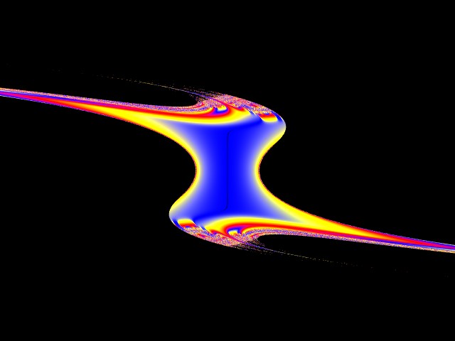
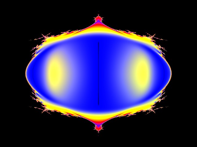
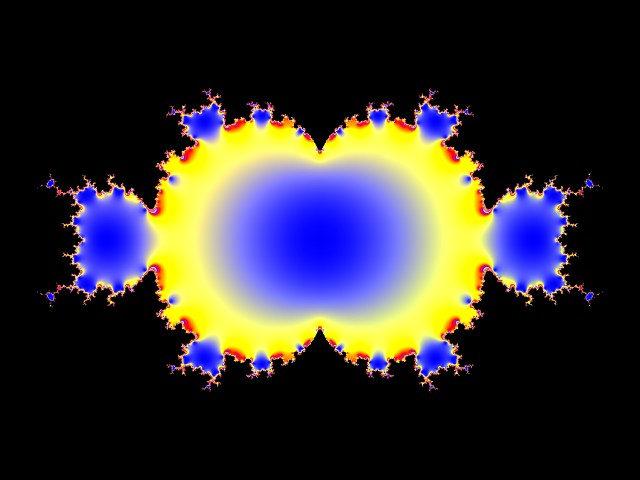
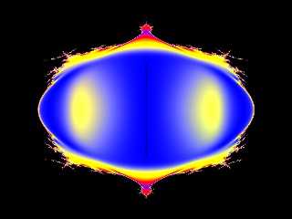
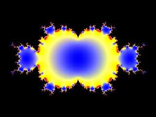
Here are cross sections through the three axes. I used 12 iterations here
(pigment functions are a lot faster than 3d isosurfaces).
Here's the source code for the Z axis slice:-
// Just useful.
#declare ReMul = function (Xr, Xi, Yr, Yi) {Xr * Yr - Xi * Yi};
#declare ImMul = function (Xr, Xi, Yr, Yi) {Xr * Yi + Xi * Yr};
#declare Re2 = function (Zr, Zi) { Zr*Zr - Zi*Zi};
#declare Im2 = function (Zr, Zi) {2*Zr*Zi};
#declare Re3 = function (Zr, Zi) { Zr*Zr*Zr - 3*Zr*Zi*Zi};
#declare Im3 = function (Zr, Zi) {3*Zr*Zr*Zi - Zi*Zi*Zi};
// Change if you like...
#declare End = function (Zr, Zi) {Zr*Zr + Zi*Zi};
// Build recursive definition...
#declare Fn = array[21];
#declare Fn[0] = function (Zr, Zi, Tr, Ti, Br, Bi) {End(Zr, Zi)};
#declare lp=1;
#while (lp<21)
#declare Fn[lp] = function (Zr, Zi, Tr, Ti, Br, Bi)
{
Fn[lp-1]
(
Re3(Zr, Zi) - ReMul(Zr, Zi, Tr, Ti) + Br,
Im3(Zr, Zi) - ImMul(Zr, Zi, Tr, Ti) + Bi,
Tr, Ti, Br, Bi
)
};
#declare lp = lp + 1;
#end
#undef lp
// Change this at will... (Must be < 20 tho.)
#declare Iterations = 12;
// Don't touch...
#declare InitP = function (Ar, Ai, Br, Bi) {Fn[Iterations](+Ar, +Ai,
3*Re2(Ar, Ai), 3*Im2(Ar, Ai), Br, Bi)};
#declare InitM = function (Ar, Ai, Br, Bi) {Fn[Iterations](-Ar, -Ai,
3*Re2(Ar, Ai), 3*Im2(Ar, Ai), Br, Bi)};
// Now draw something!!
camera
{
location <0, 0, -4.5>
look_at <0, 0, 0>
}
plane {z,0
pigment {
function {min(InitP(z, 0, x, y) - 4, 10)}
colour_map {
[0 rgb <0,0,0>]
[0.0001 rgb <0,0,1>]
[0.33 rgb <1,1,0>]
[0.67 rgb <1,0,0>]
[1.0 rgb <0,0,1>]
}
}
finish {ambient 1}
rotate z*90
scale 2
}
Post a reply to this message
Attachments:
Download '2DMandelY.jpg' (28 KB)
Download '2DMandelX.jpg' (37 KB)
Download '2DMandel.jpg' (42 KB)
Preview of image '2DMandelY.jpg'
Preview of image '2DMandelX.jpg'
Preview of image '2DMandel.jpg'
|
|
| |
| |
|
|
|
|
| |
| |
|
|
On Wed, 15 Jun 2005 11:48:59 +0100, "Mike Williams"
<nos### [at] econym demoncouk> wrote:
>Here are cross sections through the three axes. I used 12 iterations here
>(pigment functions are a lot faster than 3d isosurfaces).
>
>Here's the source code for the Z axis slice:-
It doesn't colour cycle :-)
Regards
Stephen demoncouk> wrote:
>Here are cross sections through the three axes. I used 12 iterations here
>(pigment functions are a lot faster than 3d isosurfaces).
>
>Here's the source code for the Z axis slice:-
It doesn't colour cycle :-)
Regards
Stephen
Post a reply to this message
|
|
| |
| |
|
|
|
|
| |
| |
|
|
>>Also of interest: slice the isosurface and stick a matching 2D plot on
>>the cross-section! (I will do this later if I figure out pigment
>>functions...)
>
>
> Here are cross sections through the three axes. I used 12 iterations here
> (pigment functions are a lot faster than 3d isosurfaces).
Neat!
The bottom image looks like one would expect. The other two look like I
maybe messed up my maths somewhere... they don't look right somehow.
The bottom image I'm guessing is A=(0, 0), B=(x, y). That looks correct.
If you try A=(x, y), B=(0, 0) it should look like this:
http://www.felicite-parmentier.freeserve.co.uk/large/cubic-mand.gif
However, it looks like the second image is trying to be that, but messed
up. Looks like I need to go recheck my math! (You'll notice that the
image that looks right doesn't use A at all - and there's an
optimisation involved with the A variable. Wanna bet I optimised it wrong?)
Anyways, usually when rendered 2D, the part of the isosurface that's
solid is coloured black, and the parts outside are multicoloured. ;-) Of
course, there's no *law* about that...
I'll go see if I can figure out if/where my code is wrong. :-S
Post a reply to this message
|
|
| |
| |
|
|
|
|
| |
| |
|
|
Wasn't it Orchid XP v2 who wrote:
>>>Also of interest: slice the isosurface and stick a matching 2D plot on
>>>the cross-section! (I will do this later if I figure out pigment
>>>functions...)
>>
>>
>> Here are cross sections through the three axes. I used 12 iterations here
>> (pigment functions are a lot faster than 3d isosurfaces).
>
>Neat!
>
>The bottom image looks like one would expect. The other two look like I
>maybe messed up my maths somewhere... they don't look right somehow.
>
>The bottom image I'm guessing is A=(0, 0), B=(x, y). That looks correct.
>If you try A=(x, y), B=(0, 0) it should look like this:
>
>http://www.felicite-parmentier.freeserve.co.uk/large/cubic-mand.gif
>
>However, it looks like the second image is trying to be that, but messed
>up. Looks like I need to go recheck my math! (You'll notice that the
>image that looks right doesn't use A at all - and there's an
>optimisation involved with the A variable. Wanna bet I optimised it wrong?)
>
>Anyways, usually when rendered 2D, the part of the isosurface that's
>solid is coloured black, and the parts outside are multicoloured. ;-) Of
>course, there's no *law* about that...
>
>I'll go see if I can figure out if/where my code is wrong. :-S
I suspect that it has something to do with the values of T1 and T2.
When A=(0,0), T1=0 and T2=0, and the whole thing behaves exactly like a
conventional 2D cubic Mandlebrot (z = z^3 + #pixel as they say in an
UltraFractal script).
--
Mike Williams
Gentleman of Leisure
Post a reply to this message
|
|
| |
| |
|
|
|
|
| |
| |
|
|
>>The bottom image looks like one would expect. The other two look like I
>>maybe messed up my maths somewhere... they don't look right somehow.
>>
>>I'll go see if I can figure out if/where my code is wrong. :-S
>
> I suspect that it has something to do with the values of T1 and T2.
Indeed - that's the optimisation.
The formula is z^3 - 3a^2z + b, as - as an optimisation - my code
calculates t = 3a^2. Then the formula is z^3 - tz + b.
Still... I'm staring at my code... and I'm not seeing anything wrong...
hmmmm... 0:-)
Post a reply to this message
|
|
| |
| |
|
|
|
|
| |
| |
|
|
Wasn't it Emerald Orchid who wrote:
>>>The bottom image looks like one would expect. The other two look like I
>>>maybe messed up my maths somewhere... they don't look right somehow.
>>>
>>>I'll go see if I can figure out if/where my code is wrong. :-S
>>
>> I suspect that it has something to do with the values of T1 and T2.
>
>Indeed - that's the optimisation.
>
>The formula is z^3 - 3a^2z + b, as - as an optimisation - my code
>calculates t = 3a^2. Then the formula is z^3 - tz + b.
>
>Still... I'm staring at my code... and I'm not seeing anything wrong...
>hmmmm... 0:-)
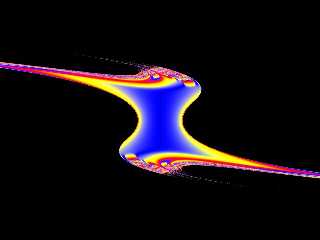
I just spotted that the formula for the image you want it to look like
appears in the title bar of the gif. Namely:
Z = Z^3 - 3.c^2.Z + 0
However, the function you're using for the 3D mandelbrot is
Z = Z^3 - 3.c^2.Z + #pixel
on the X plane cross section, the real part of the #pixel is 0
This code plots Z = Z^3 - 3.c^2.Z + 0 using something similar to your
original 3D function, but I can't see how to get something 3D that does
this on the X axis and plots Z = Z^3 + #pixel on the Z axis at the same
time.
// Just useful.
#declare ReMul = function (Xr, Xi, Yr, Yi) {Xr * Yr - Xi * Yi};
#declare ImMul = function (Xr, Xi, Yr, Yi) {Xr * Yi + Xi * Yr};
#declare Re2 = function (Zr, Zi) { Zr*Zr - Zi*Zi};
#declare Im2 = function (Zr, Zi) {2*Zr*Zi};
#declare Re3 = function (Zr, Zi) { Zr*Zr*Zr - 3*Zr*Zi*Zi};
#declare Im3 = function (Zr, Zi) {3*Zr*Zr*Zi - Zi*Zi*Zi};
// Change if you like...
#declare End = function (Zr, Zi) {Zr*Zr + Zi*Zi};
// Build recursive definition...
#declare Fn = array[21];
#declare Fn[0] = function (Zr, Zi, Tr, Ti, Br, Bi) {End(Zr, Zi)};
#declare lp=1;
#while (lp<21)
#declare Fn[lp] = function (Zr, Zi, Tr, Ti, Br, Bi)
{
Fn[lp-1]
(
Re3(Zr, Zi) - ReMul(Zr, Zi, Tr, Ti) + Br,
Im3(Zr, Zi) - ImMul(Zr, Zi, Tr, Ti) + Bi,
Tr, Ti, Br, Bi
)
};
#declare lp = lp + 1;
#end
#undef lp
// Change this at will... (Must be < 20 tho.)
#declare Iterations = 12;
// Don't touch...
#declare InitP = function (Ar, Ai, Br, Bi) {Fn[Iterations](+Ar, +Ai,
3*Re2(Ar, Ai), 3*Im2(Ar, Ai), Br, Bi)};
#declare InitM = function (Ar, Ai, Br, Bi) {Fn[Iterations](-Ar, -Ai,
3*Re2(Ar, Ai), 3*Im2(Ar, Ai), Br, Bi)};
// Now draw something!!
camera
{
location <0, 0, -4.5>
look_at <0, 0, 0>
}
light_source {<-2, +3, -5>, colour rgb <1.0, 0.0, 1.0>}
light_source {<+2, -3, -5>, colour rgb <0.0, 1.0, 0.0>}
plane {x,0
pigment {
function {min(InitP(z, y, x, 0) - 4, 10)} // changed this
colour_map {
[0 rgb <0,0,0>]
[0.0001 rgb <0,0,1>]
[0.33 rgb <1,1,0>]
[0.67 rgb <1,0,0>]
[1.0 rgb <0,0,1>]
}
}
finish {ambient 1}
scale 2
rotate <0,90,90>
}
--
Mike Williams
Gentleman of Leisure
Post a reply to this message
|
|
| |
| |
|
|
|
|
| |
|
|