|
|
|
|
|
|
| |
| |
|
|
From: William F Pokorny
Subject: Normal documentation images. Quilted.
Date: 11 Oct 2020 09:22:46
Message: <5f830726@news.povray.org>
|
|
|
| |
| |
|
|
Some days back, Bald Eagle, privately asked me about a comment in
POV-Ray's source code. One mentioning floor() and the FLOOR() macro. The
comment suggests the latter did some mirroring. After a wrong answer or
two, I now believe FLOOR() was always about performance regardless of
code comments - and so functionally not what the quilted coders expected.

With hexagon the two FLOOR() uses are buying performance. Plus, the
results in that case are identical to floor() due the inputs being
conditioned positive.

With quilted's FLOOR() use - in both implementations - it's harder to
determine what's happening. With it, I think someone was expecting
plus/minus axis mirroring - and not getting it.

I created quilted test cases and reviewed the shipped demo scenes. A
number of other issues popped out. One of which is the 'true normal'
results do not match what our documentation shows for quilted normals.

This led me to allnormals.pov which, IIRC, is used for the normal{}
pattern images in the documentation. The set up is shown below and it's
'wrong' as indicated for normal{ <true normal-pattern> } images(1)):

#declare Agate         = normal {pigment_pattern{agate
#WRONG   Average       = normal {pigment_pattern{average
#declare Boxed         = normal {pigment_pattern{boxed
#declare Bozo          = normal {pigment_pattern{bozo
#declare Brick         = normal {pigment_pattern{brick
#WRONG   Bumps         = normal {pigment_pattern{bumps
#declare Cells         = normal {pigment_pattern{cells
#declare Checker       = normal {pigment_pattern{checker
#declare Crackle       = normal {pigment_pattern{crackle
#declare Cylindrical   = normal {pigment_pattern{cylindrical
#WRONG   Dents         = normal {pigment_pattern{dents
#declare Mandel        = normal {pigment_pattern{mandel
#declare Julia         = normal {pigment_pattern{julia
#declare Facets        = normal {facets
#declare Function      = normal {pigment_pattern{function
#declare Gradient      = normal {pigment_pattern{gradient
#declare Granite       = normal {pigment_pattern{granite
#declare Hexagon       = normal {pigment_pattern{hexagon
#declare Image_pattern = normal {pigment_pattern{image_pattern
#declare Leopard       = normal {pigment_pattern{leopard
#declare Marble        = normal {pigment_pattern{marble
#declare Onion         = normal {pigment_pattern{onion
#declare Planar        = normal {pigment_pattern{planar
#WRONG   Quilted       = normal {pigment_pattern{quilted
#declare Radial        = normal {pigment_pattern{radial
#WRONG   Ripples       = normal {pigment_pattern{ripples
#declare Spherical     = normal {pigment_pattern{spherical
#declare Spiral1       = normal {pigment_pattern{spiral1
#declare Spiral2       = normal {pigment_pattern{spiral2
#declare Spotted       = normal {pigment_pattern{spotted
#WRONG   Waves         = normal {pigment_pattern{waves
#declare Wood          = normal {pigment_pattern{wood
#WRONG   Wrinkles      = normal {pigment_pattern{wrinkles

Why is allnormals.pov not showing the normal{} version of the pattern
when there is one? (Excepting facets as there's no 'value for map'
version of that pattern.)

The documentation today is confusing with respect to normal{} pattern use.

Where there is a normal specific version of the pattern, we have a
trifecta of possible schemes/results. A 'value for map' pattern result
such as used with a pigment map; A 'value for map' result where sampled
pattern values are used to perturb the surface's normal vector; Lastly,
a normal specific, 'perturbed normal vector' result.

(1) The html generated by allnormals.pov has the statement: "Most of the
patterns, used as a normal." It could, thinly, be argued to be off the
hook by taking pattern to mean the 'value for map' version of perturbed
normals, but...

----
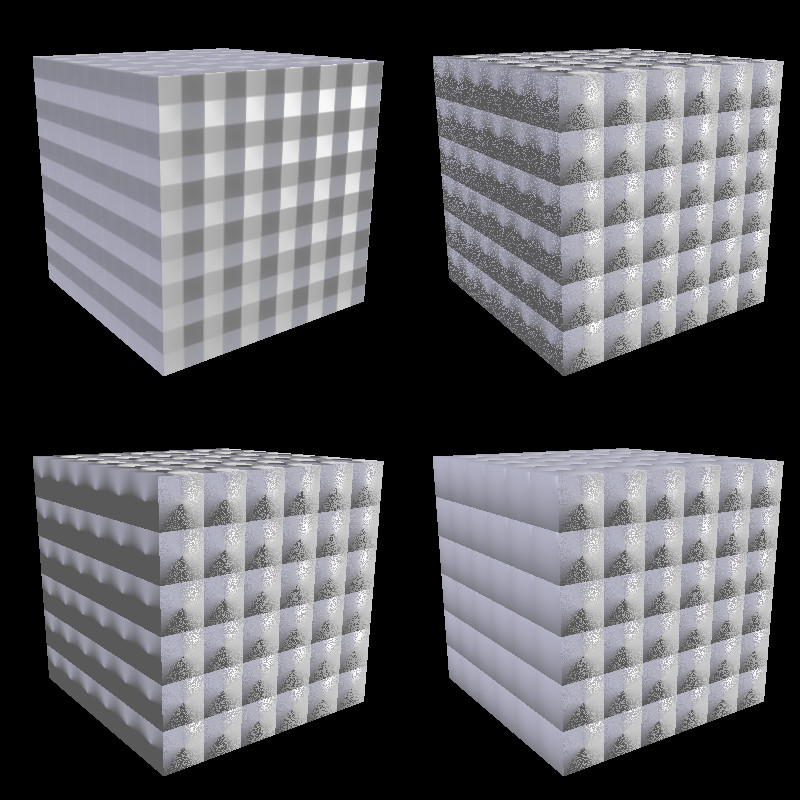
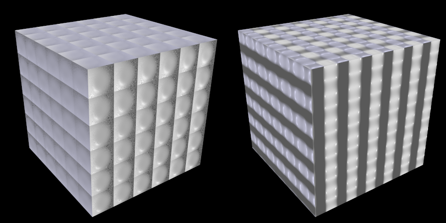
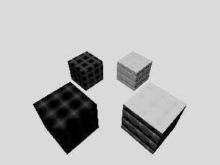
Attached is an image - generated with v3.8 master - showing additional
quilted specific issues.

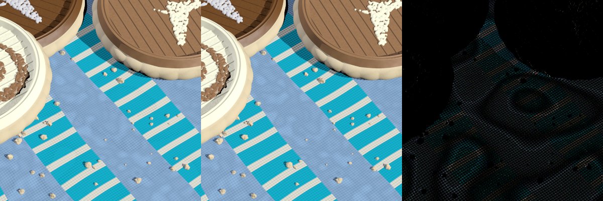
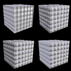
In the upper left is the 'value for map' pattern surface normal
perturbation. Internally, the map pattern's value is sampled four times
and those samples are used to perturb the shape's surface normal. The
normal block's accuracy setting comes into play here. Beyond that, I've
not worked through what the code is really doing.

In the upper right is today's (v3.7/v3.8) true normal { quilted ... }
result. It shows one of the longstanding issues with the quilted normal
perturbation implementation. Specifically, if the shape's surface
"lands" on any of the texture's axial "floors" during texture
evaluation, you get a noisy result.

The usual fix for that sort of problem is to apply a small positive or
negative epsilon - somewhere - in the system being calculated so such
landings are unlikely in practice. Checker does this internal to the
pattern code. It's that epsilon adjustment I made too small back in
March with povr changes. The quilted's true normal pattern leaves this
epsilon value fudging to users.

In the lower left I shrunk the pattern by a tiny epsilon to nudge the
system off the floor. The noise goes away on the negative x axis. The
the perturbed normal vector also partly inverts! This another
longstanding issue. One which happens over half of each unit interval
along each axis.

In the lower right I expanded the pattern by a tiny epsilon. The noise
is again gone on the -x surface. This time it looks 'quilted.'

Why is the -z face still seeing noise no matter the pattern scaling?

It's because the allnormals.pov template scene translates the shapes +z
by an amount that puts the cube's front face on the 0.0, z, normal
pattern floor during evaluation. To fix this face, one has to adjust
that surface so it lands less unfortunately. The 0.0 position is a
special case that pattern and shape sizing cannot fix.

By sizing a shape by epsilon we can get the perturbed normal polarity
right for only half the cube surfaces at once. Fixing all six requires
sizing, translation and particular placement in the quilted pattern.

Additionally, from other test cases, it looks to me like the quilted
normal has a negative axis bias (no expected FLOOR() mirroring?). The
depth/strength of the perturbed normals is not constant with axially
perpendicular surface position. Non-symmetrical shapes are more
complicated to position well in the pattern.

All said, I believe the normal perturbation quilted code can be tweaked
to eliminate most (all?) of the issues.

There are fewer gotchas in the quilted 'value for map' pattern though
one springs to mind.

The code has long set the quilted's default wave shaping frequency to
0.0(2). I 'suspect' this was to avoid (now old to povr) wave shaping
fudge factor artifacts. Anyway, the point being, the phase modifier
doesn't work by default due this default - and that's not documented.

Further, anyone 'can' set frequency to something other than 0.0 and
phase will suddenly be active again - as will the 0-1 fudge factor
fmod-ing the frequency 0 setting is 'probably' hoping to avoid.

(2) - Yep, there's more that could be said here. This 'Easter egg,' sdl
available mechanism is gone in povr.

I'll add, the 'value map' version of quilted isn't quilted in appearance.

---
For povr, my current plan is to make better the true normal perturbation
quilted code and delete the quilted 'value for map' pattern. Quilted
then to become like facets in normal behavior in having only a normal{}
version. We'll see.

Bill P.
Post a reply to this message
Attachments:
Download 'realnrmlstory.jpg' (147 KB)
Preview of image 'realnrmlstory.jpg'
|
|
| |
| |
|
|
|
|
| |
| |
|
|
William F Pokorny <ano### [at] anonymous org> wrote:
>
> In the upper right is today's (v3.7/v3.8) true normal { quilted ... }
> result. It shows one of the longstanding issues with the quilted normal
> perturbation implementation. Specifically, if the shape's surface
> "lands" on any of the texture's axial "floors" during texture
> evaluation, you get a noisy result.
>
> The usual fix for that sort of problem is to apply a small positive or
> negative epsilon - somewhere - in the system being calculated so such
> landings are unlikely in practice.
Thanks for looking into this. I have always suspected that the quilted pattern
(at least as a 'normal') has some unexpected quirks.
Back in April 2018, I actually posted an animation test about this, with some
notes; perhaps it would prove helpful...
http://news.povray.org/povray.binaries.animations/thread/%3Cweb.5ae6126fe8495210a47873e10%40news.povray.org%3E/
I too found that I needed to add a slight positioning 'fudge factor' to the
pattern in my SDL code (like your internal epsilon tweaking) to avoid the
'noise' that you described. I also think that the pattern has some kind of
'discontinuity'-- in other words, that it does not seem to be uniform in its
behavior throughout its unit(?)-cube spatial volume. The effect is hard to
describe; maybe my animation will make it clear. I had assumed that the pattern
'spread out' or expanded from a central point-- so that it would perturb all six
faces of a cube in an equal way; but the visual result looks...odd. org> wrote:
>
> In the upper right is today's (v3.7/v3.8) true normal { quilted ... }
> result. It shows one of the longstanding issues with the quilted normal
> perturbation implementation. Specifically, if the shape's surface
> "lands" on any of the texture's axial "floors" during texture
> evaluation, you get a noisy result.
>
> The usual fix for that sort of problem is to apply a small positive or
> negative epsilon - somewhere - in the system being calculated so such
> landings are unlikely in practice.
Thanks for looking into this. I have always suspected that the quilted pattern
(at least as a 'normal') has some unexpected quirks.
Back in April 2018, I actually posted an animation test about this, with some
notes; perhaps it would prove helpful...
http://news.povray.org/povray.binaries.animations/thread/%3Cweb.5ae6126fe8495210a47873e10%40news.povray.org%3E/
I too found that I needed to add a slight positioning 'fudge factor' to the
pattern in my SDL code (like your internal epsilon tweaking) to avoid the
'noise' that you described. I also think that the pattern has some kind of
'discontinuity'-- in other words, that it does not seem to be uniform in its
behavior throughout its unit(?)-cube spatial volume. The effect is hard to
describe; maybe my animation will make it clear. I had assumed that the pattern
'spread out' or expanded from a central point-- so that it would perturb all six
faces of a cube in an equal way; but the visual result looks...odd.
Post a reply to this message
|
|
| |
| |
|
|
|
|
| |
| |
|
|
On 10/11/20 4:03 PM, Kenneth wrote:
> William F Pokorny <ano### [at] anonymousorg> wrote:
>>
>> In the upper right is today's (v3.7/v3.8) true normal { quilted ... }
>> result. It shows one of the longstanding issues with the quilted normal
>> perturbation implementation. Specifically, if the shape's surface
>> "lands" on any of the texture's axial "floors" during texture
>> evaluation, you get a noisy result.
>>
>> The usual fix for that sort of problem is to apply a small positive or
>> negative epsilon - somewhere - in the system being calculated so such
>> landings are unlikely in practice.
>
> Thanks for looking into this. I have always suspected that the quilted pattern
> (at least as a 'normal') has some unexpected quirks.
>
> Back in April 2018, I actually posted an animation test about this, with some
> notes; perhaps it would prove helpful...
>
>
http://news.povray.org/povray.binaries.animations/thread/%3Cweb.5ae6126fe8495210a47873e10%40news.povray.org%3E/
>
> I too found that I needed to add a slight positioning 'fudge factor' to the
> pattern in my SDL code (like your internal epsilon tweaking) to avoid the
> 'noise' that you described. I also think that the pattern has some kind of
> 'discontinuity'-- in other words, that it does not seem to be uniform in its
> behavior throughout its unit(?)-cube spatial volume. The effect is hard to
> describe; maybe my animation will make it clear. I had assumed that the pattern
> 'spread out' or expanded from a central point-- so that it would perturb all six
> faces of a cube in an equal way; but the visual result looks...odd.
>
>

Hi. Thank you for the pointer. I missed your original post - or it got
lost in my old noggin...

Aside: The video played, but was blank for me, until the last few frames
on my raspbian last night. It's OK on this machine this morning. Who
knows :-).

No doubt you found some of quilted's complications. I "think" I
understand most of what's happening and why. We'll see.

I believe any updated code should 'perturb' with the original surface
normal in mind. I see a path to do this with flat surface stuff like
cubes, but I don't know how to do it for curved surfaces in normal.cpp.

The facets pattern has a curved surface method. I'll have to see if I
can digest what was done there.

A simpler approach would be to warp normals constructed flat to common
shapes. However, there's that block of un-finished normal warp / unwarp
related code. I see it, but I don't really understand what works and
doesn't with normals tangled in warps.

Truth is, I don't use normals that often. My todo list is effectively
infinite. No promises as to when I can make things better with povr
quilted normals. I'm about 95% sure I'll remove the value version of
quilted from povr and replace it with 'seedfi' pattern(s?).

Bill P.
Post a reply to this message
|
|
| |
| |
|
|
|
|
| |
| |
|
|
On 10/11/20 9:22 AM, William F Pokorny wrote:
> This led me to allnormals.pov which, IIRC, is used for the normal{}
> pattern images in the documentation. The set up is shown below and it's
> 'wrong' as indicated for normal{ <true normal-pattern> } images(1)):

well i don't know / recall... perhaps t / d stamp can provide some
guidance. the 1st link shows what is likely the initial load when wiki
was being setup, the 2nd shows Jerome made a change... maybe his memory
is better than mine!


http://wiki.povray.org/content/File:RefImgQuiltpt4.gif

http://wiki.povray.org/content/File:RefImgQuiltedNormal.png
Post a reply to this message
|
|
| |
| |
|
|
|
|
| |
| |
|
|
On 10/12/20 7:11 AM, Ash Holsenback wrote:
> On 10/11/20 9:22 AM, William F Pokorny wrote:
>> This led me to allnormals.pov which, IIRC, is used for the normal{}
>> pattern images in the documentation. The set up is shown below and
>> it's 'wrong' as indicated for normal{ <true normal-pattern> } images(1)):
>
> well i don't know / recall... perhaps t / d stamp can provide some
> guidance. the 1st link shows what is likely the initial load when wiki
> was being setup, the 2nd shows Jerome made a change... maybe his memory
> is better than mine!

lol... 11 and 6 years ago!!! holy crap... lately last week is ancient
history. senility must be setting in
Post a reply to this message
|
|
| |
| |
|
|
|
|
| |
| |
|
|
William F Pokorny <ano### [at] anonymousorg> wrote:

> No doubt you found some of quilted's complications. I "think" I
> understand most of what's happening and why. We'll see.
>
> I believe any updated code should 'perturb' with the original surface
> normal in mind. I see a path to do this with flat surface stuff like
> cubes, but I don't know how to do it for curved surfaces in normal.cpp.

Maybe you could write a scene trying to express the quilted pattern in SDL as a
function?
Sometimes it's a bit difficult to translate the somewhat cryptic C++ syntax into
something intelligible.
Then at least you could have a few people play with the function and have more
eyes and minds analyzing how it all works, and where it goes wrong.

Including a note or two about how to translate the C++ to SDL (if possible)
would help future efforts, and people could begin to play with more of the
source code and patterns.   I have found this approach to be personally
educational, developmentally useful  (how many "bugs" have we found?), and it
inspires me to invent new derivative functions and patterns.
Post a reply to this message
|
|
| |
| |
|
|
|
|
| |
| |
|
|
William F Pokorny <ano### [at] anonymousorg> wrote:

> I created quilted test cases and reviewed the shipped demo scenes. A
> number of other issues popped out. One of which is the 'true normal'
> results do not match what our documentation shows for quilted normals.

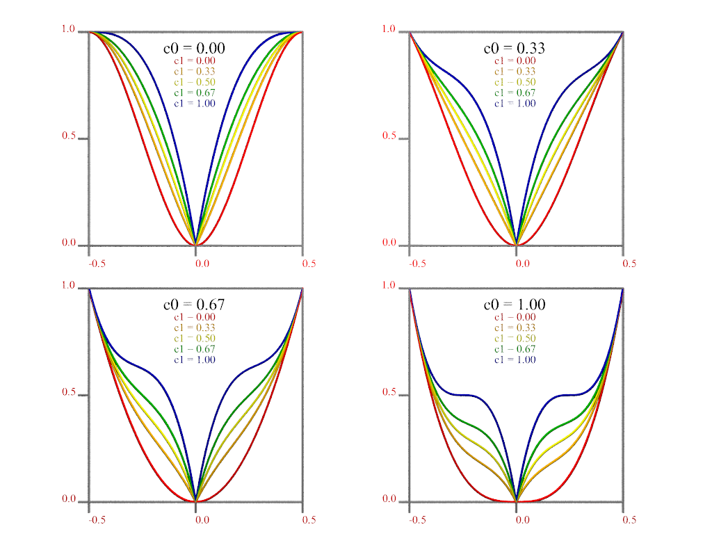
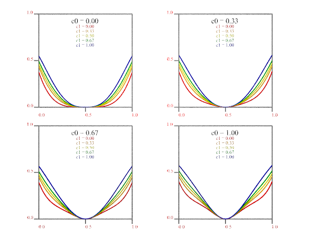
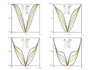
Perhaps I'm wrong or misreading something, but it doesn't appear that the
documentation properly describes the pattern.

http://wiki.povray.org/content/Reference:Quilted_Pattern

Just looking at the last image,
"A control value of 1 at both ends will give an "s" shaped curve, resulting in a
softer, more rounded edge."
yet the solid line is the s-shaped curve, and it says for that c1 = 0.

After skimming through the source code in patterns and normals, the basic
formula used to generate the curve seems an awful lot like a specialized form of
bicubic spline with c0 and c1 influencing the internal two control points...

but it's ... bizarrely different.
And I can't reproduce the curves and s-shape reliably.
And I don't know why they don't use a function based on 2*x, or use mod(), ...
Post a reply to this message
|
|
| |
| |
|
|
|
|
| |
| |
|
|
Pfft.
I rolled my own and came up with more or less the same curves, but the way the
parameters influence them is different (of course...).

Maybe I can adapt this into a pigment pattern and a normal.

Do we know who made, how, and where the files are for the illustrations at:
http://wiki.povray.org/content/Reference:Quilted_Pattern ?

That would be a huge help.
Post a reply to this message
Attachments:
Download 'newquiltedpattern.png' (205 KB)
Preview of image 'newquiltedpattern.png'
|
|
| |
| |
|
|
From: William F Pokorny
Subject: Re: Normal documentation images. Quilted.
Date: 13 Oct 2020 03:57:11
Message: <5f855dd7@news.povray.org>
|
|
|
| |
| |
|
|
On 10/12/20 2:35 PM, Bald Eagle wrote:
> William F Pokorny <ano### [at] anonymousorg> wrote:
...
>
> Maybe you could write a scene trying to express the quilted pattern in SDL as a
> function?
>
> Including a note or two about how to translate the C++ to SDL (if possible)
> would help future efforts, and people could begin to play with more of the
> source code and patterns.
>

Hmm. More automatic c++ -> sdl idea interesting. Some things wouldn't be
doable at all, but certain stuff would be more or less - I guess. Busy
with real life today and tomorrow won't leave me a lot of time, but I'll
stick the idea in my head and start to let it bang around in there.

Bill P.
Post a reply to this message
|
|
| |
| |
|
|
|
|
| |
| |
|
|
On 10/12/20 7:44 PM, Bald Eagle wrote:
> William F Pokorny <ano### [at] anonymousorg> wrote:
>
>> I created quilted test cases and reviewed the shipped demo scenes. A
>> number of other issues popped out. One of which is the 'true normal'
>> results do not match what our documentation shows for quilted normals.
>
> Perhaps I'm wrong or misreading something, but it doesn't appear that the
> documentation properly describes the pattern.
>
> http://wiki.povray.org/content/Reference:Quilted_Pattern
>
> Just looking at the last image,
> "A control value of 1 at both ends will give an "s" shaped curve, resulting in a
> softer, more rounded edge."
> yet the solid line is the s-shaped curve, and it says for that c1 = 0.
>
> After skimming through the source code in patterns and normals, the basic
> formula used to generate the curve seems an awful lot like a specialized form of
> bicubic spline with c0 and c1 influencing the internal two control points...
>
> but it's ... bizarrely different.
> And I can't reproduce the curves and s-shape reliably.
> And I don't know why they don't use a function based on 2*x, or use mod(), ...
>

Yes, I'm not quite sure what's going on there either.

Though I specified defaults of 1 and 1 it looked to me more like 1 and 0
or 0 and 1 depending on how the normals flip on the half unit
intervals... I didn't dive into it. ;-)

One of the complications is the curves as shown have one value inputs.
The result we 'see' is a combination of three applications to three
input values. Ahhh, as I expect you know! :-)

Bill P.
Post a reply to this message
|
|
| |
| |
|
|
|
|
| |
| |
|
|
On 10/12/20 10:47 PM, Bald Eagle wrote:
> Pfft.
> I rolled my own and came up with more or less the same curves, but the way the
> parameters influence them is different (of course...).
>
> Maybe I can adapt this into a pigment pattern and a normal.
>
> Do we know who made, how, and where the files are for the illustrations at:
> http://wiki.povray.org/content/Reference:Quilted_Pattern ?

well as far as who and how... don't know. the where is on the wiki...
just click on the image to bring up revision info. given my confusion
about your question i'm guessing my response is a swing and a miss
Post a reply to this message
|
|
| |
| |
|
|
|
|
| |
| |
|
|
Ash Holsenback <no### [at] spamcom> wrote:
> On 10/12/20 10:47 PM, Bald Eagle wrote:
> > Pfft.
> > I rolled my own and came up with more or less the same curves, but the way the
> > parameters influence them is different (of course...).
> >
> > Maybe I can adapt this into a pigment pattern and a normal.
> >
> > Do we know who made, how, and where the files are for the illustrations at:
> > http://wiki.povray.org/content/Reference:Quilted_Pattern ?
>
> well as far as who and how... don't know. the where is on the wiki...
> just click on the image to bring up revision info. given my confusion
> about your question i'm guessing my response is a swing and a miss

Jim,


From the source code,
Who:

* FUNCTION
*
*   quilted_pattern

* AUTHOR
*
*   Dan Farmer & Chris Young

As for how - those function graphs didn't make themselves, so I'm wondering what
source information was used and how those graphs were generated for the
documentation.
Their existence implies some (non-POV-Ray?) file(s) that were used to graph the
function, and those might shed some additional light the issue.


-BW
Post a reply to this message
|
|
| |
| |
|
|
|
|
| |
| |
|
|
"Bald Eagle" <cre### [at] netscapenet> wrote:
> Pfft.
> I rolled my own and came up with more or less the same curves, but the way the
> parameters influence them is different (of course...).
>
> Maybe I can adapt this into a pigment pattern and a normal.

Played around a bit more.
It seems that the quilted pattern uses a radial/spherical distance as the
driving parameter for the function, whereas I thought using a min max formula
for a box would give a "distance formula" that tracked the square/cubic shape.

It also seems that the quilted normal is an inverted function from the pigment
pattern, as I need to use 1-Fn(x,y,z) to get the same effect (convex face, with
concave edges)

Stock quilted in foreground (control0 0 control1 0), my function in the back
(c0=1 c1=0)

SO many things here have touched on what I learned and developed in past
projects.
rounded box isosurface
bilinear interpolation pattern
Bezier bicubic spline
space-tesselating patterns and isosurfaces
crackle/Delaunay/Voronoi wips

No ideas at this point about performance or numerical stability with regard to
the offsets, etc.
Post a reply to this message
Attachments:
Download 'newquiltedpatternandnormal.png' (93 KB)
Preview of image 'newquiltedpatternandnormal.png'
|
|
| |
| |
|
|
|
|
| |
| |
|
|
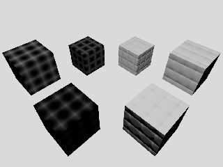
Added a spherical/Cartesian length function version.
(Midway, right/left)

Looks pretty similar to the stock quilted.

Still throwing darts in the dim light....
Post a reply to this message
Attachments:
Download 'newquiltedpatternandnormal.png' (138 KB)
Preview of image 'newquiltedpatternandnormal.png'
|
|
| |
| |
|
|
|
|
| |
| |
|
|
On 10/13/20 1:55 PM, Bald Eagle wrote:
> As for how - those function graphs didn't make themselves, so I'm wondering what
> source information was used and how those graphs were generated for the
> documentation.
> Their existence implies some (non-POV-Ray?) file(s) that were used to graph the
> function, and those might shed some additional light the issue.

indeed... that is likely. all i got when i did the initial load was a
tarball that i still have access to... i looked and that's what we have
for the graphs. i was curious because i thought it /might/ have been
among some of the latex i converted. if you feel inclined to produce a
set of new images, post them here and i'll replace on the wiki
Post a reply to this message
|
|
| |
| |
|
|
|
|
| |
| |
|
|
On 10/13/20 4:55 PM, Bald Eagle wrote:
> Added a spherical/Cartesian length function version.
> (Midway, right/left)
>
> Looks pretty similar to the stock quilted.
>
> Still throwing darts in the dim light....
>

I'd guess there isn't much use in translating the non-working normal.cpp
quilted code so below is an my initial attempt at a fix for surfaces
perpendicular to the x, y and z axis. This updated code passes most of
my test cases but of course has varying results with respect to curved
surfaces - as does the original.  Whether this is what we want for a
best quilted fix - I don't know! I don't think we really know what the
original coders expected or perhaps even got to one degree or another in
older versions of code

One puzzle for me is I looked at no_bump_scale in the upper right render
(C).  I expected it to have some effect on all three surfaces, but it's
only changing the -x one! Not dug into code. Anyone have an idea what's
going on? This touches on me not being a big user of normals. Not sure
I've ever used no_bump_scale myself.

DBL just means double - an sdl float. The normal is the incoming normal.
  fabs is abs in sdl. The () ? ... : ... stuff is select. floor and ceil
are floor and ceil. The quilt_cubic you, Bill, understand better than me
at this point.

This the sort of thing you're looking for?

----------
DBL nx = normal.x(), ny = normal.y(), nz = normal.z();
DBL ax = fabs(nx),   ay = fabs(ny),   az = fabs(nz);

DBL x = EPoint.x(), y = EPoint.y(), z = EPoint.z();
DBL flx = floor(x), fly = floor(y), flz = floor(z);
DBL sx = (x-flx < 0.5) ? -1 : 1,
     sy = (y-fly < 0.5) ? -1 : 1,
     sz = (z-flz < 0.5) ? -1 : 1;
DBL xm = flx+(ceil(flx+4.4e-8)-flx)/2.0;
DBL ym = fly+(ceil(fly+4.4e-8)-fly)/2.0;
DBL zm = flz+(ceil(flz+4.4e-8)-flz)/2.0;

DBL c0 = pattern->Control0, c1 = pattern->Control1;
DBL na = Tnormal->Amount;

if ((ax >= ay) && (ax >= az))
{
     DBL vy = quilt_cubic(fabs(y-ym),c0,c1)*sy;
     DBL vz = quilt_cubic(fabs(z-zm),c0,c1)*sz;
     nz = (nz < 0.0) ? -1 : 1;
     ny = ny + (na * vy);
     nz = nz + (na * vz);
}
else if ((ay >= ax) && (ay >= az))
{
     DBL vx = quilt_cubic(fabs(x-xm),c0,c1)*sx;
     DBL vz = quilt_cubic(fabs(z-zm),c0,c1)*sz;
     nx = nx + (na * vx);
     ny = (ny < 0.0) ? -1 : 1;
     nz = nz + (na * vz);
}
else
{
     DBL vx = quilt_cubic(fabs(x-xm),c0,c1)*sx;
     DBL vy = quilt_cubic(fabs(y-ym),c0,c1)*sy;
     nx = nx + (na * vx);
     ny = ny + (na * vy);
     nz = (nz < 0.0) ? -1 : 1;
}
normal = Vector3d(nx,ny,nz);
normal.normalize();  // <-- this normal vector what gets updated.

---------
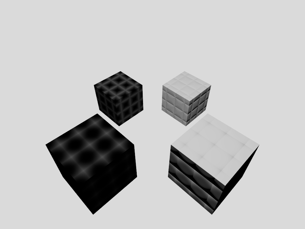
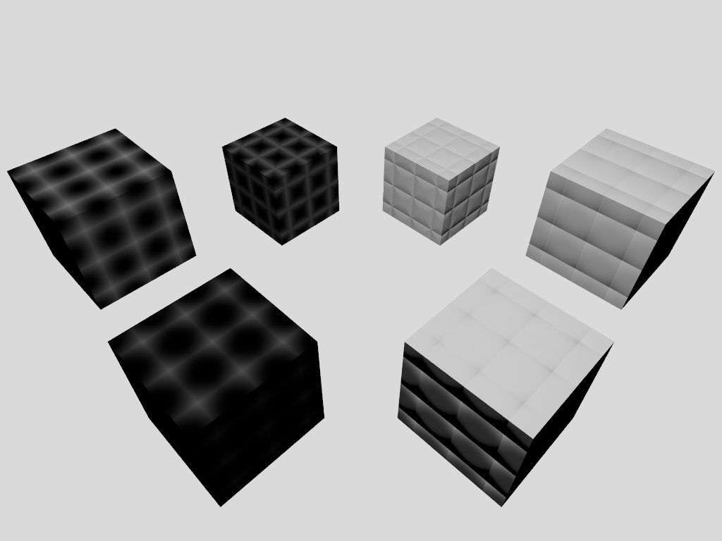
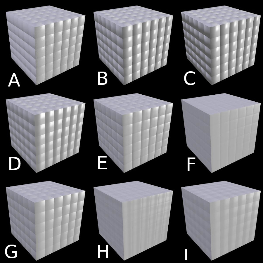
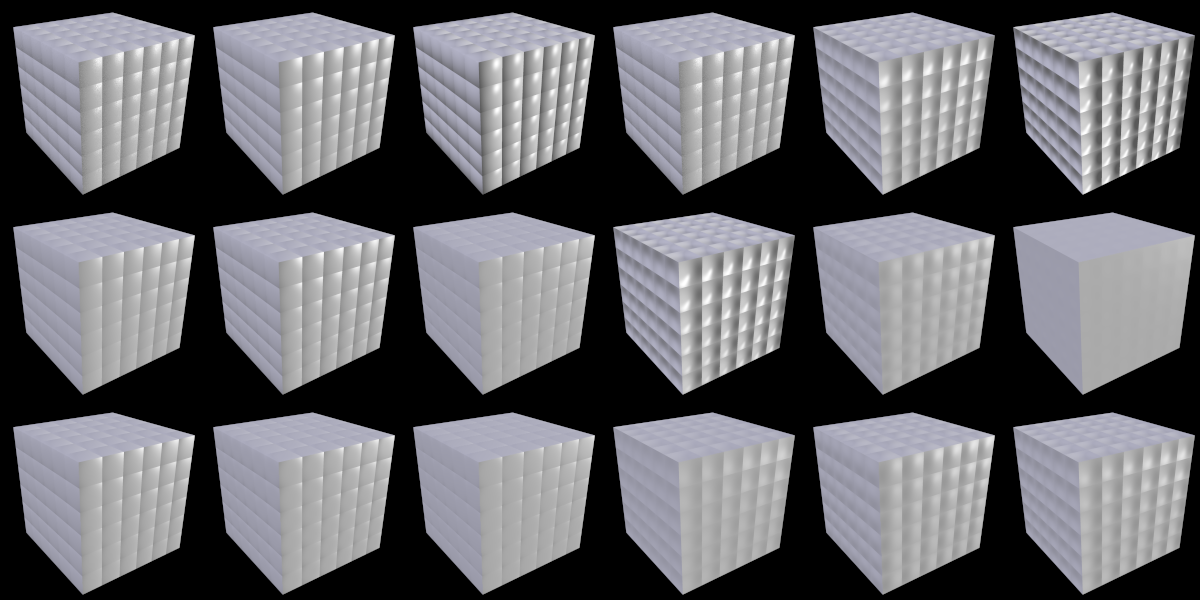
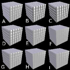
All images in attached image using AA. Why noisy v3.8 results of(A)
looks less noisy at the expense of being quite slow.

A) v3.8 at master.
normal {quilted 0.5 control0 +1.0 control1 +1.0 scale 0.5}

B) povr with a fix.
normal {quilted 0.5 control0 +1.0 control1 +1.0 scale 0.5}

C) normal {quilted 0.5 control0 +1.0 control1 +1.0
no_bump_scale scale 0.5}

D) normal {quilted 0.5 control0 +0.0 control1 +1.0 scale 0.5}
E) normal {quilted 0.5 control0 +1.0 control1 +0.0 scale 0.5}
F) normal {quilted 0.5 control0 +0.0 control1 +0.0 scale 0.5}

G) normal {quilted 0.5 control0 +0.3 control1 +0.3 scale 0.5}
H) normal {quilted 0.5 control0 -0.3 control1 +0.3 scale 0.5}
I) normal {quilted 0.5 control0 +0.3 control1 -0.3 scale 0.5}

Bill P.
Post a reply to this message
Attachments:
Download 'aquiltednormalfix.jpg' (137 KB)
Preview of image 'aquiltednormalfix.jpg'
|
|
| |
| |
|
|
|
|
| |
| |
|
|
William F Pokorny <ano### [at] anonymousorg> wrote:

> I'd guess there isn't much use in translating the non-working normal.cpp
> quilted code so

Translating the non-working code would help reproduce the nonworkability.
Then we could see where and why it doesn't work.

> below is an my initial attempt at a fix for surfaces
> perpendicular to the x, y and z axis.

But what did you fix?

> This updated code passes most of
> my test cases but of course has varying results with respect to curved
> surfaces - as does the original.  Whether this is what we want for a
> best quilted fix - I don't know! I don't think we really know what the
> original coders expected or perhaps even got to one degree or another in
> older versions of code

I'm not sure what you mean about curved surfaces - no examples have been
provided.

> One puzzle for me is I looked at no_bump_scale in the upper right render
> (C).  I expected it to have some effect on all three surfaces, but it's
> only changing the -x one! Not dug into code. Anyone have an idea what's
> going on? This touches on me not being a big user of normals. Not sure
> I've ever used no_bump_scale myself.

You haven't supplied any of your scene code, so I can't tell if you have any
scaling or offsets.  The wiki says that no_bump_scale just cancels out any
scaling of the normal depth when the texture or normal itself is scaled.

> DBL just means double - an sdl float. The normal is the incoming normal.
>   fabs is abs in sdl. The () ? ... : ... stuff is select. floor and ceil
> are floor and ceil. The quilt_cubic you, Bill, understand better than me
> at this point.

I'll address that and the code supplied below right here.
What I was looking for was as close to a 1:1 translation from the original
source code written in c++ to how it would be done with functions in SDL if it
were written that way from scratch.

Not sure where you are pulling the code below from, but what I had found was:


const DBL INV_SQRT_3_4 = 1.154700538;


DBL quilt_cubic(DBL t, DBL p1, DBL p2)
{
 DBL it=(1-t);
 DBL itsqrd=it*it;
 // DBL itcubed=it*itsqrd;
 DBL tsqrd=t*t;
 DBL tcubed=t*tsqrd;
 DBL val;
 // Originally coded as...
 // val= (DBL)(itcubed*n1+(tcubed)*n2+3*t*(itsqrd)*p1+3*(tsqrd)*(it)*p2);
 //re-written by CEY to optimise because n1=0 n2=1 always.
 val = (tcubed + 3.0*t*itsqrd*p1 + 3.0*tsqrd*it*p2) * INV_SQRT_3_4;
 return(val);
}


And so my first attempt at translating that was:

#declare INV_SQRT_3_4 = 1.154700538;
#declare Floor = function (T) {select (T, floor (1-T), floor (T))}
#declare IT = function (T) {1-T}
#declare ITsqr = function (T) {pow(IT (T), 2)}
#declare Tsqr = function (T) {pow(T, 2)}
#declare Tcub = function (T) {pow(T, 3)}
#declare Val0 = function (T, _P1, _P2) {
(
pow(T, 3) +
(3 * T * pow(1-T, 2) * _P1) +
(3 * pow(T,2) * (T - pow(T, 2)) * _P2)
)
* INV_SQRT_3_4

}

So:
I would say that if we could get that working as a pigment {function{}}
statement and as a normal{function{}}, then we should be able to then graph it
out the way I did mine to emulate the graphs in the documentation.
They _should_ match (aside from any misleading typos in the docs)

As for the underlying problems with the raytraced result of the pattern, I can
only speculate:
1. it's a function gradient problem since the function may be discontinuous,
have cusps, or whatever else resulting from the use of floor(), etc - since it's
a function designed to be constrained to a unit cube.
I'll have to look at what the isosurface looks like, etc.

2.  There's some interface problem between the output of the function and the
rest of what happens to that information after it gets evaluated and sent down
the ray / surface rendering pipeline.

As for the normal-specific function, I'd just need a very basic and specific
explanation of exactly how a given surface normal gets perturbed, in general (by
any user-written scalar function{}), and specifically by this function.
Just so it's crystal clear to me -  because what direction does a +y normal get
tilted to? It has 360 degrees of directions to get perturbed in.

I'd also need the following three statements in c++ syntax decrypted, so I could
try translating those into SDL.

    const QuiltedPattern *pattern =
dynamic_cast<QuiltedPattern*>(Tnormal->pattern.get());

    POV_PATTERN_ASSERT(pattern);

and

    normal += (DBL)Tnormal->Amount * value;


> This the sort of thing you're looking for?
>
> ----------
> DBL nx = normal.x(), ny = normal.y(), nz = normal.z();
> DBL ax = fabs(nx),   ay = fabs(ny),   az = fabs(nz);
>
> DBL x = EPoint.x(), y = EPoint.y(), z = EPoint.z();
> DBL flx = floor(x), fly = floor(y), flz = floor(z);
> DBL sx = (x-flx < 0.5) ? -1 : 1,
>      sy = (y-fly < 0.5) ? -1 : 1,
>      sz = (z-flz < 0.5) ? -1 : 1;
> DBL xm = flx+(ceil(flx+4.4e-8)-flx)/2.0;
> DBL ym = fly+(ceil(fly+4.4e-8)-fly)/2.0;
> DBL zm = flz+(ceil(flz+4.4e-8)-flz)/2.0;
>
> DBL c0 = pattern->Control0, c1 = pattern->Control1;
> DBL na = Tnormal->Amount;
>
> if ((ax >= ay) && (ax >= az))
> {
>      DBL vy = quilt_cubic(fabs(y-ym),c0,c1)*sy;
>      DBL vz = quilt_cubic(fabs(z-zm),c0,c1)*sz;
>      nz = (nz < 0.0) ? -1 : 1;
>      ny = ny + (na * vy);
>      nz = nz + (na * vz);
> }
> else if ((ay >= ax) && (ay >= az))
> {
>      DBL vx = quilt_cubic(fabs(x-xm),c0,c1)*sx;
>      DBL vz = quilt_cubic(fabs(z-zm),c0,c1)*sz;
>      nx = nx + (na * vx);
>      ny = (ny < 0.0) ? -1 : 1;
>      nz = nz + (na * vz);
> }
> else
> {
>      DBL vx = quilt_cubic(fabs(x-xm),c0,c1)*sx;
>      DBL vy = quilt_cubic(fabs(y-ym),c0,c1)*sy;
>      nx = nx + (na * vx);
>      ny = ny + (na * vy);
>      nz = (nz < 0.0) ? -1 : 1;
> }
> normal = Vector3d(nx,ny,nz);
> normal.normalize();  // <-- this normal vector what gets updated.


> C) normal {quilted 0.5 control0 +1.0 control1 +1.0
> no_bump_scale scale 0.5}

So, as I currently understand it, if the default bump_size is 1.0, then
no_bump_scale decouples the bump_size from the scale 0.5 statement, so that the
area of the normal gets scaled, but the bump_size stays the same at 1.0 instead
of getting shrunk to 0.5 .
Post a reply to this message
|
|
| |
| |
|
|
|
|
| |
| |
|
|
And the other thing that's throwing me off is what exactly are the function
inputs and outputs.

I was trying to graph the built-in quilted pattern before I headed out, and got
some curved inverted "V" shapes instead of anything resembling the documentation
shapes.

#declare CN = array [5] {0, 0.33, 0.5, 0.67, 1}
#local c0 = CN[0];
#for (c1, 0, 4)
#ifdef (Q) #undef Q #end
#declare Q = function {pigment {quilted control0 c0 control1 CN[c1]}}
.....

Then it struck me that the function probably isn't using linear x at the surface
of the cube where I see the pattern - it's using the vector length of <x,y,z>,
and spitting out --- a scalar.

So if I get the native pattern function worked out and graph it, I'll be sure to
LABEL THE AXES this time 'round.

'till then, hi ho, hi ho....
Post a reply to this message
|
|
| |
| |
|
|
|
|
| |
| |
|
|
On 10/14/20 4:07 PM, Bald Eagle wrote:
> William F Pokorny <ano### [at] anonymousorg> wrote:
>
>> I'd guess there isn't much use in translating the non-working normal.cpp
>> quilted code so
>
> Translating the non-working code would help reproduce the nonworkability.
> Then we could see where and why it doesn't work.

No doubt it might help you and perhaps others play with that code, but
suppose I believe I've already sorted through the issues with the
normal.cpp code as it was. I don't recall anything extra needed for
translation to SDL over what I posted and I know you know where the code
is based upon your questions below. :-)

>
>> below is an my initial attempt at a fix for surfaces
>> perpendicular to the x, y and z axis.
>
> But what did you fix?

All the bugs about which I previously posted - and a couple lessor about
which I did not write. ;-)

We are only handling cube and flat surfaces without distortion. There
thinking about it more the documentation - it is pretty clear the about
the application being via unit cubes.

My fix amounts to being axis-projective within each unit cube - taking
care with the polarity of the original normals and the '2D' offsets with
respect to the unit square's two center axes. Maybe we forget trying to
make 'quilted' work for other than via projection or on flat surfaces
surfaces.

Beyond that, you and I have questions as to whether the control point
graphs and descriptions are correct with respect to the pattern(1). An
update to these so they are better looking and generated with generated
POV-Ray code is a good idea no matter. Christoph often made arguments
for this and the v3.8 documentation has taken steps in this direction.

Plus, I now have cases with the no_bump_scale where I don't understand
what is happening. Your interpretation matches mine - which makes me
think there is another bug somewhere in the normals handling, but this
one probably outside quilted itself.

And I rambled a little about there being unfinished warp related normal
code. With this I expect some warps beyond transforms are not working
correctly, but I've never explored in this direction. These issues are
outside the quilted code itself in any case.

(1) - With the initial povr fix in place it looks to me as if the center
of the square face relates to control point 0 and control point 1 the
edges. One and one values is a rounded at both ends and two and two
flat. Negative values inverts the curvature so you can get for example
tile looking faces where the corners are slightly raised relative to the
centers - which I think is kinda cool.

Argh, here I am writing chapters of books again...

What to do when questions are simple; folks want simple answers, but the
situations are, with even a single feature, brutally complicated. :-(

>
>> This updated code passes most of
>> my test cases but of course has varying results with respect to curved
>> surfaces - as does the original.  Whether this is what we want for a
>> best quilted fix - I don't know! I don't think we really know what the
>> original coders expected or perhaps even got to one degree or another in
>> older versions of code
>
> I'm not sure what you mean about curved surfaces - no examples have been
> provided.
>
A sphere say. For example, and though there is turbulence, you can see
the issue with the shipped quilt1 scene using the current quilted normal
implementation. The curved surface is catching parts of the cube rather
than adjusting with the surface curvature. As said above. I think we
just let this go as is for quilted. Not to say we cannot work on and
implement something better.

>> One puzzle for me is I looked at no_bump_scale in the upper right render
>> (C).  I expected it to have some effect on all three surfaces, but it's
>> only changing the -x one! Not dug into code. Anyone have an idea what's
>> going on? This touches on me not being a big user of normals. Not sure
>> I've ever used no_bump_scale myself.
>
> You haven't supplied any of your scene code, so I can't tell if you have any
> scaling or offsets.  The wiki says that no_bump_scale just cancels out any
> scaling of the normal depth when the texture or normal itself is scaled.
>
Yeah, sorry, I meant to say in my post I just hacked the allnormals.pov
replacing the:

#declare Quilted = normal {...}

declare with the normal{} blocks indicated. FWIW. I also changed the T
texture to read:

#declare T=texture {
     pigment {rgb 1}
     normal { Quilted }  // <--- This
     finish {phong 0.5 phong_size 20}
}

So I wouldn't have to play with animation flags.

>
> And so my first attempt at translating that was:
>
> #declare INV_SQRT_3_4 = 1.154700538;
...
> #declare IT = function (T) {1-T}
> #declare ITsqr = function (T) {pow(IT (T), 2)}
> #declare Tsqr = function (T) {pow(T, 2)}
> #declare Tcub = function (T) {pow(T, 3)}
> #declare Val0 = function (T, _P1, _P2) {
> (
> pow(T, 3) +
> (3 * T * pow(1-T, 2) * _P1) +
> (3 * pow(T,2) * (T - pow(T, 2)) * _P2)
> )
> * INV_SQRT_3_4
>
> }
>

To my eye that looks good. I'll give it a try an maybe code up and
in-built using the original c++ coding and compare to be paranoid. I see
wanting to see this as a pigment (easier in povr due negative values).
Not sure what you are after with the normal{} test...

>
> 2.  There's some interface problem between the output of the function and the
> rest of what happens to that information after it gets evaluated and sent down
> the ray / surface rendering pipeline.

Yes. One apparent in the initial "DBL it=(1-t);" the function is
expecting inputs in the range of 0 to 1 because it's inverting on that
range, but we are not providing it exactly that range(2). In fact in the
normal version the value strengths passed are varying as we move a
surface along the axis in the cube.

(2) - And neither am I in my initial re-code. This maybe needs
adjustment...

It has 360 degrees of directions to get perturbed in.

And that's a problem. It needs to be perturb only in the half sphere of
the original surface normal. Something I think my code addresses.

>
> I'd also need the following three statements in c++ syntax decrypted, so I could
> try translating those into SDL.
>
>      const QuiltedPattern *pattern =
> dynamic_cast<QuiltedPattern*>(Tnormal->pattern.get());
>
>      POV_PATTERN_ASSERT(pattern);
>
> and
>
>      normal += (DBL)Tnormal->Amount * value;
>

The first two amoung to getting the correct object pattern pointer type
to get access to the two control values. This is one place where my povr
code had already diverged. In my code this is coded:

POV_PATTERN_ASSERT(dynamic_cast<QuiltedPattern*>(Tnormal->pattern.get())
!= nullptr);

const QuiltedPattern *pattern =
static_cast<QuiltedPattern*>(Tnormal->pattern.get());

so we only take the hit of the dynamic_cast run time checking if certain
debug settings are on during a compile. The POV_PATTERN_ASSERT does
nothing in a regular compile. (Aside: one thing I noticed in the future
debian work is they currently have such a debug enabled version of
povray as possible install version.)

Ah, dang. And your question about "normal += (DBL)Tnormal->Amount *
value;" makes obvious I forgot to do that step in my re-code! Thanks. I
was getting a normal scaling of 1.0 despite coding 0.5 due this. :-)

Oh, that statement is adding an adjustment vector - one scaled by the
normal patterns sizing value (and/or bump_size in at least some
patterns) - to the original surface normal. The is the "perturb the
normal" step.

...
>
> So, as I currently understand it, if the default bump_size is 1.0, then
> no_bump_scale decouples the bump_size from the scale 0.5 statement, so that the
> area of the normal gets scaled, but the bump_size stays the same at 1.0 instead
> of getting shrunk to 0.5 .
>
Thanks. Guess I need to dig into the cause for the asymmetry in
application seen here.

Bill P.
Post a reply to this message
|
|
| |
| |
|
|
|
|
| |
| |
|
|
William F Pokorny <ano### [at] anonymousorg> wrote:

> Beyond that, you and I have questions as to whether the control point
> graphs and descriptions are correct with respect to the pattern(1). An
> update to these so they are better looking and generated with generated
> POV-Ray code is a good idea no matter. Christoph often made arguments
> for this and the v3.8 documentation has taken steps in this direction.

Yes, I think that such a thing would help answer most of the usual questions
about implementation, syntax, limitations, artefacts and other issues, etc.

Something using #switch to control the scene would allow easy generation of the
official documentation image, but with supplemental code showing variations and
slick tricks that one can do with the pattern.


> A sphere say. For example, and though there is turbulence, you can see
> the issue with the shipped quilt1 scene using the current quilted normal
> implementation. The curved surface is catching parts of the cube rather
> than adjusting with the surface curvature. As said above. I think we
> just let this go as is for quilted. Not to say we cannot work on and
> implement something better.

I have a "quilted.pov" scene - but yes, I understand (it's what I thought).
Same as if you use checkered.
Don't you just use uv_mapping to fix that?

> To my eye that looks good. I'll give it a try an maybe code up and
> in-built using the original c++ coding and compare to be paranoid. I see
> wanting to see this as a pigment (easier in povr due negative values).
> Not sure what you are after with the normal{} test...

You said the normal had different properties / handling than the pattern.  So
I'm treating them as two separate things.

> It has 360 degrees of directions to get perturbed in.
>
> And that's a problem. It needs to be perturb only in the half sphere of
> the original surface normal. Something I think my code addresses.

I mean that I don't understand exactly how a normal gets perturbed if I plug
some scalar function into a normal {} statement.
The top of a cube has a normal of +y.
If I perturb that normal, it gets tilted.
But in what direction?   I STILL have a full 360 degrees of a circle to choose
from - the tilt needs to be directional, but there is no basis vector
information associated with the scalar of the function.
Does the +y get tilted in the +x direction?  The +z direction?
Is it dependent on the light source or camera vector?


> Thanks. Guess I need to dig into the cause for the asymmetry in
> application seen here.

I must admit that I can't really see from your examples what the problem is -
but if you see it and it's real....
Post a reply to this message
|
|
| |
| |
|
|
|
|
| |
| |
|
|
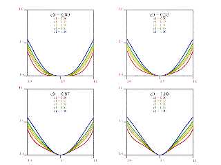
So here's what I'm getting out of

function {pigment {quilted control0 c0 control1 CN[c1]}}

and varying all components of the input vector from 0 to 1 at the same time.
#for (X, 0, 1, 0.01)
#local QX = Q (X, X, X);

plots of QX.x QX.y and QX.z are all the same, and the transmit and filter
components are always 0

So I have no idea where the documentation graphs come from.

I _must_ be doing _something_ wrong....
Post a reply to this message
Attachments:
Download 'quilteddocumentation_38.png' (78 KB)
Preview of image 'quilteddocumentation_38.png'
|
|
| |
| |
|
|
|
|
| |
| |
|
|
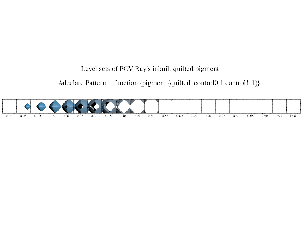
So I wanted to check on the size and position of the pattern, given the graphs
in the docs go from -0.5 to 0.5.
The base pattern exists in a cube from <0, 0, 0> to <1, 1, 1>.

Which means it's centered at <0.5, 0.5, 0.5>, and the graph must be showing a
sort of signed axial distance.
But the function NEVER attains a value of 1.

Just to "see it all", I rendered 20 isosurfaces of 'quilted' with thresholds
from 0 to 1.

It just doesn't jive with the graphs showing a function returning values of from
0 to 1 inclusive.  Nor with the changing shape of the curves.
(And I did loop through and evaluate all of the c0 and c1 values and just plot
them all on top of one another.  Nothing reached 1, nothing stood out as an
S-shaped curve.)

It _does_ agree with the graphs I made showing it topping out at ~0.55.

Lucy... you got some 'splainin' to do....
Post a reply to this message
Attachments:
Download 'quilteddimensions.png' (46 KB)
Preview of image 'quilteddimensions.png'
|
|
| |
| |
|
|
|
|
| |
| |
|
|
On 10/15/20 3:13 PM, Bald Eagle wrote:
> William F Pokorny <ano### [at] anonymousorg> wrote:
>
...
>

I'll attempt to respond to your recent questions with this post while
rambling too about what I've recently come to understand.

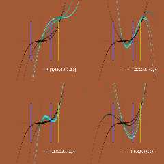
First, I think we missed a mistake in the translation of quilt_cubic. I
believe the correct SDL is:

#declare INV_SQRT_3_4 = 1.154700538; // 1.0/sqrt(3.0/4.0) used in povr
#declare IT = function (T) {1-T}
#declare ITsqr = function (T) {pow(IT (T), 2)}
#declare Tsqr = function (T) {pow(T, 2)}
#declare Tcub = function (T) {pow(T, 3)}
#declare Val0 = function (T, _P1, _P2) {
(
pow(T, 3) +
(3 * T * pow(1-T, 2) * _P1) +
(3 * pow(T,2) * (1-T) * _P2)
)
* INV_SQRT_3_4
}

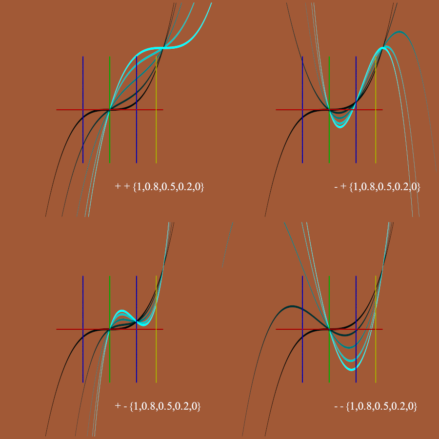
I've attached an image of 4 renders using iosurfaces of the function to
plot.  In each plotting results using x at T and using different set
control magnitudes. In each of the four flip the polarity of the control
points as indicated.

Here speaking about the true normal vector perturbation method - ie
normal {quilted..} - what I'm interested in for povr.  The old quilted
sent values to quilt_cubic in the range of 0 to 0.867. This is the
yellow vertical line in the plots.  My initial re-code is using values
in the range of 0 to 0.5 because it seemed to work well - as do then,
negative control values. Meaning in the current re-code, -1 to 1
control1 and control2 values are OK. Larger magnitudes can be used too,
but results less and less real world like - especially in the negative
direction. (Negative control values 'function' in the current v3.8
quilted too)

At it's best, the old true normal quilted looks a little more
quilted/pillow-y than my current re-code, but the re-code offers much
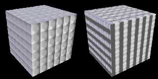
more stable results. Plus, you can now get other effects with wacko
control values. I've attached a second image with a v38 render (noisy)
and a povr render with the control values set to +9.6 and -9.6.

---
On the issue I was seeing with no_bump_scale. I saw what I saw because
of a typo in my original re-code. A typo which caused the +-x axis to
work as usual!  Once I stopped trying to internally normalize all 3
dimensions, things work as before for no_bump_scale.

The no_bump_scale turns off the normalization of the incoming surface
normal. Because we are perturbing incoming normals with the true normal
patterns, using the option affects the strength of the perturbation for
all scales not 1 in magnitude. The 'bump_size' value does too - as does
any non-symmetric scaling. The normal perturbation path can be
complicated.

When normals are used in ray direction and color calculations, they are
always normalized to a length of 1.0. In other words, the magnitude of
the normal doesn't matter at this point. Everything we do perturbing
normals has to do with setting the resultant normal direction(a).

(a) - Excepting setting the normal strength to 0 which nulls the normal
effects - though as I write this, I'm unsure what happens with ior
calculations when the normal is zeroed...

Partly by the feature name, I suspect no_bump_scale was first aimed at
bump maps where the depth of the normal at each vertex in patch based
surfaces gets interpolated with the normals on the other corners of the
patch. Some tooling does this in any case.

I'm unsure what happens with triangles and normal interpolation in
POV-Ray with respect to normal magnitudes? Anyone know? When I've played
myself with meshes and setting normals, I've always normalized them.

------- Your questions.
 > Don't you just use uv_mapping to fix that?

Yes, that is a way to get what you want for shapes with uv mapping. In
POV-Ray there are often many ways to approach some result. ;-)

 > How the normal pattern perturbation works?

My current understanding...

For true normal patterns, essentially, an adder vector is calculated
then weighted by the normal strength / bump_size value (0.5 default)
before it gets added to the incoming surface normal. That incoming
normal may or may not have been normalized depending upon the
no_bump_scale setting.

For "value for map" based normals the values are perturbed and this
affects the pyramid of samples around the surface point and so the
resultant normal direction. I think the no_bump_scale must do nothing
then? - but I've not tested this thought. It is with this form the
normal accuracy default or user setting is used.

 > How to explain the -0.5 to 0.5 bottom axis of the plots in the
documentation?

Not sure. Perhaps the values intended to represent the +-magnitudes of
the possible x, y and z offsets from the center of each cube into the
function. So a graph not really a function graph, but something meant to
help users understand quilted? I now lean toward a c0,c1 grid of results
(-1,+1) as a guide over plots of an internal function used in part to
get some final effect.

Bill P.
Post a reply to this message
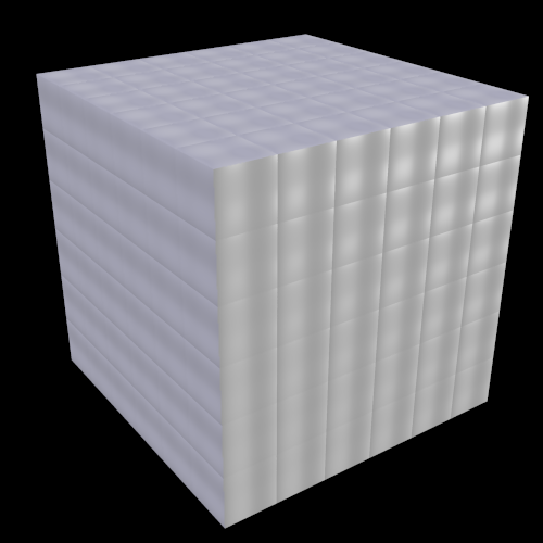
Attachments:
Download 'cubic_quilt_story.png' (123 KB)
Download 'v38_vs_povr_pn9pt6.png' (224 KB)
Preview of image 'cubic_quilt_story.png'
Preview of image 'v38_vs_povr_pn9pt6.png'
|
|
| |
| |
|
|
|
|
| |
| |
|
|
William F Pokorny <ano### [at] anonymousorg> wrote:

>
> I'd guess there isn't much use in translating the non-working normal.cpp
> quilted code so below is an my initial attempt at a fix for surfaces
> perpendicular to the x, y and z axis. This updated code passes most of
> my test cases...Whether this is what we want for a
> best quilted fix - I don't know!

The majority of these look quite good, in my opinion, except for odd-looking -H-
(I think one of its control points is negative.) Its inverted(?) pillow look is
kind of hard to discern, though. It would be interesting to see it with a higher
bump value.
Post a reply to this message
|
|
| |
| |
|
|
|
|
| |
| |
|
|
On 10/17/20 10:49 PM, Kenneth wrote:
> William F Pokorny <ano### [at] anonymousorg> wrote:
>>
>> I'd guess there isn't much use in translating the non-working normal.cpp
>> quilted code so below is an my initial attempt at a fix for surfaces
>> perpendicular to the x, y and z axis. This updated code passes most of
>> my test cases...Whether this is what we want for a
>> best quilted fix - I don't know!
>
> The majority of these look quite good, in my opinion, except for odd-looking -H-
> (I think one of its control points is negative.) Its inverted(?) pillow look is
> kind of hard to discern, though. It would be interesting to see it with a higher
> bump value.
>

I've attached an hhh.png image with a bump_size of 1 instead of the
default 0.5. The corners are raised relative to the middle parts. The
apparent offset in each cube is due two lights of different colors and
shading due light position.

---
I keep thrashing around on what to do fix wise with the true quilted
normal pattern...

One of the weird things with the existing implementation is the x,y,z
coordinates in the unit cube are all, always used in a distance from
unit cube center calculation. This meant the quilt_cubic function was
getting an over all range of values from 0 to 0.867.

However, at any given face position in the unit cube the range of values
fed to quilt_cubic was in fact a sub range of the 0 to 0.867 range. At
the unit face it was 0.5 to 0.867 (values delta of 0.367). At face
positions moving inward toward 0.0 the delta range moved and increased
in size (to 0.707 on the floor).

We could go a different way for a fix. One which implements the
previous, unit cube centered, face results by default, but which now
offers an offset keyword. The offset would let users slide a 0.367 delta
value range around as fed to the quilt_cubic function. Sort of a left /
right slider for the posted quilt_cubic curves. (Back to the function's
curves having meaning...)

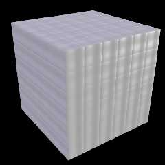
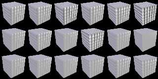
Attached is a second image quiltedOptionTwo.png. The left set of 9 is
the same A to I set. Here it's what users would see at the unit faces
with the existing implementation (ignoring the noise issue). The offset
is 0.5 for these. In the right set of 9, I've used an offset of -1.0.
Many of the faces invert (inside of the pillow) and the results are more
pillow like.

Is this a better way to go for a fix?

This offset keyword would allow users having existing scenes at face
positions not on the full unit cube to achieve a previous result (in
conjunction with bump magnitude) - at least where it wasn't previously
some corrupt, partly inverted result.

Aside: The thrashing here gets back to an early question of Bald
Eagle's. Why not calculate 0-1 face input values for a Bezier curve
where the user specifies both end points in addition to the control
points. It looks to me like this was closer to the form of the original
internal equation; later simplified.

Today suppose, that form of 'quilted_cubic' would better be an inbuilt
function. Users could do what ever they wanted with it. Maybe I'll play
with that too. Could be done with a spline based function, but a limited
inbuilt should be quite a bit faster.

Bill P.
Post a reply to this message
Attachments:
Download 'hhh.png' (87 KB)
Download 'quiltedoptiontwo.png' (343 KB)
Preview of image 'hhh.png'
Preview of image 'quiltedoptiontwo.png'
|
|
| |
| |
|
|
|
|
| |
| |
|
|
William F Pokorny <ano### [at] anonymousorg> wrote:

> I keep thrashing around on what to do fix wise with the true quilted
> normal pattern...
>
> One of the weird things with the existing implementation is the x,y,z
> coordinates in the unit cube are all, always used in a distance from
> unit cube center calculation. This meant the quilt_cubic function was
> getting an over all range of values from 0 to 0.867.

Yes.  None of the vector components ever exceeded +/-0.5, and so
sqrt( pow(x,2) + pow(y,2) + pow(z,2) ) =
sqrt (0.25 + 0.25 + 0.25) =
sqrt (0.75) =
0.866025404

However, you're omitting the fact that the end result of the calculations was
them multiplied by 1/(sqrt(3/4) = 1.154700538
and 0.866025404 * 1.154700538 = 1.0

> However, at any given face position in the unit cube the range of values
> fed to quilt_cubic was in fact a sub range of the 0 to 0.867 range. At
> the unit face it was 0.5 to 0.867 (values delta of 0.367). At face
> positions moving inward toward 0.0 the delta range moved and increased
> in size (to 0.707 on the floor).

Because at N = 0, one of the vector components was always 0, and so the equation
would then be
sqrt (0.25 + 0.25 + 0) =
sqrt (0.5) =
0.707106781

This is the reason why in my initial coding, I instead used a function
incorporating min(max( QX2(x), max(QY2(y), QZ2(z)) ), 0)
(the equation for an isosurface cube)

The idea of course being that such a method should give a constant 1.0 along the
entire surface of any given face.

> We could go a different way for a fix. One which implements the
> previous, unit cube centered, face results by default, but which now
> offers an offset keyword. The offset would let users slide a 0.367 delta
> value range around as fed to the quilt_cubic function. Sort of a left /
> right slider for the posted quilt_cubic curves. (Back to the function's
> curves having meaning...)

Not sure where that comes from:
(0.367....  0.160?   0.867-0.707?
0.866025404−0.707106781 = 0.158918623)


> This offset keyword would allow users having existing scenes at face
> positions not on the full unit cube to achieve a previous result (in
> conjunction with bump magnitude) - at least where it wasn't previously
> some corrupt, partly inverted result.

Since I got lost and I don't understand, this would be something different that
simply translating the pigment pattern by some amount would _not_ fix?

> Aside: The thrashing here gets back to an early question of Bald
> Eagle's. Why not calculate 0-1 face input values for a Bezier curve
> where the user specifies both end points in addition to the control
> points. It looks to me like this was closer to the form of the original
> internal equation; later simplified.

I'm still confused about a number of points, the most basic and direct is the
graphing of the internal quilted function results vs the documentation graphs.

> Today suppose, that form of 'quilted_cubic' would better be an inbuilt
> function. Users could do what ever they wanted with it. Maybe I'll play
> with that too. Could be done with a spline based function, but a limited
> inbuilt should be quite a bit faster.

Have not been able to invest the uninterrupted and focused time to see where the
interpretation of the quilted function went wrong, or any of that.

But with regard to using a bicubic spline, that is how I got my function to
exhibit the "inflection point" that the documentation graphs show (It's just a
flat tangent=0 point).  Actually having a function that allowed a true
inflection point would be interesting - then a tile could have a groove around
the edge, like some cutting boards do.
Post a reply to this message
|
|
| |
| |
|
|
|
|
| |
| |
|
|
"Bald Eagle" <cre### [at] netscapenet> wrote:

> > William F Pokorny <ano### [at] anonymousorg> wrote:
> > This meant the quilt_cubic function was
> > getting an over all range of values from 0 to 0.867.

Yeah, you/I should play around with PREmultiplying that by 1.15....

The implementation seems to me to be a bit unneccesarily Byzantine, and I tried
to keep the original function - but simplify it by multiplying through, and
that's how I got my interpretation of the quilted function wrong.

Your fix is indeed correct.

The part that has (still) got me mystified now is calculating the INPUT to the
quilt_cubic function, as the value function I was using with floor and FLOOR
didn't seem to make any sense.   It should be a mirrored function across 0, no?

We discussed this and I think for this application
#declare FLOOR = function (T) {floor (abs(T))}
is the kind of thing that is intended.

So to keep it simple I just do
#declare ValueX = function (X) {abs(X)-floor(abs(X))-0.5}

Then when I run through the calculations stepwise, I get something smooth and
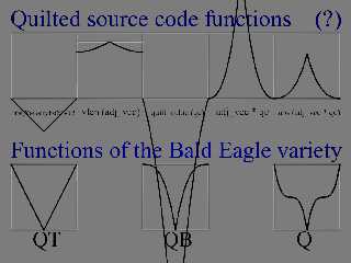
symmetric. (But holy cow - that quilt_cubic function...  :O )

Here are the graphs I got when I plotted the original quilted sub-functions in a
daisy-chained stepwise manner (range -0.5 to 0.5) compared with how I originally
did mine (range 0-1).

I _think_ it looks right, given the full black and never fully white values in
the original pattern, but I'm confused about the difference between my SDL
calculations and the full color function {quilted ....} plots I did.
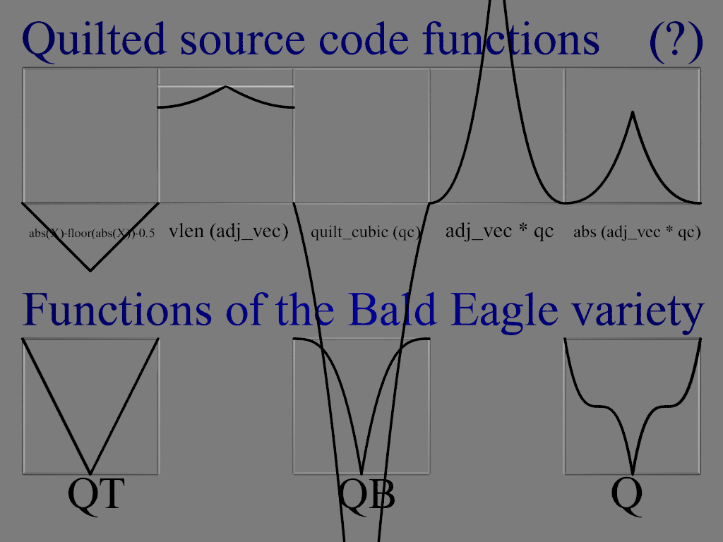
Which means I might still not be evaluating this correctly.

Given that the function {quilted ....} just gives a sort of flattened U, I'm
wondering if there might not be a simpler way to achieve THAT shape, since I
think whatever the (unlabeled) graphs were trying to convey were misleading.

The only other thing I can think of is to use a correcting function - perhaps
that can be enabled with a flag, that way new scenes could use the new or the
old way,
or implemented separately: something like pigment {function {quilted} * function
{quilt_correct}} could be done, so that extant scenes wouldn't have to be
modified at all, but new scenes could add the additional correction in.

The idea is that since there is a variation between the center of an edge and a
corner, a compensating function could be applied to make the whole edge
(reasonably) constant.

It's ugly, but "backward compatibility" always is.

My vote is to come up with a nice clean simple easy-to-understand and document
function has has none of the current problems, looks good on a single unit cube
at a large size, jettison the old code, issue a deprecation warning or "this
version of quilted is a new experimental feature, replacing the original...."
type message, and go from there.
(how many people have actually used quilted in past scenes?)
Post a reply to this message
Attachments:
Download 'quilted.png' (110 KB)
Preview of image 'quilted.png'
|
|
| |
| |
|
|
|
|
| |
| |
|
|
On 10/18/20 9:34 AM, Bald Eagle wrote:
> William F Pokorny <ano### [at] anonymousorg> wrote:
>
>> I keep thrashing around on what to do fix wise with the true quilted
>> normal pattern...
>>
>> One of the weird things with the existing implementation is the x,y,z
>> coordinates in the unit cube are all, always used in a distance from
>> unit cube center calculation. This meant the quilt_cubic function was
>> getting an over all range of values from 0 to 0.867.
>
> Yes.  None of the vector components ever exceeded +/-0.5, and so
> sqrt( pow(x,2) + pow(y,2) + pow(z,2) ) =
> sqrt (0.25 + 0.25 + 0.25) =
> sqrt (0.75) =
> 0.866025404
>
> However, you're omitting the fact that the end result of the calculations was
> them multiplied by 1/(sqrt(3/4) = 1.154700538
> and 0.866025404 * 1.154700538 = 1.0
>

Yes. I wasn't clear I was talking about the input range to the
quilt_cubic there. FWIW - the output range actually peaks out at about
1.03 and this one cause of the normal flipping which currently sometimes
happens.

>> However, at any given face position in the unit cube the range of values
>> fed to quilt_cubic was in fact a sub range of the 0 to 0.867 range. At
>> the unit face it was 0.5 to 0.867 (values delta of 0.367). At face
>> positions moving inward toward 0.0 the delta range moved and increased
>> in size (to 0.707 on the floor).
>

Dang, dang, dang... That parenthetical should have read: (to 0.707 at
the mid point between the floor and ceiling).

> Because at N = 0, one of the vector components was always 0, and so the equation
> would then be
> sqrt (0.25 + 0.25 + 0) =
> sqrt (0.5) =
> 0.707106781
>
> This is the reason why in my initial coding, I instead used a function
> incorporating min(max( QX2(x), max(QY2(y), QZ2(z)) ), 0)
> (the equation for an isosurface cube)
>
> The idea of course being that such a method should give a constant 1.0 along the
> entire surface of any given face.
>

Yes, this idea similar to the approach I took with my 2D axis projection
option. I decoupled the other two axises too in running quilt_cubic
twice for each projection. This is the option that looks less quilted
but which is more flexible with respect to effects.

>> We could go a different way for a fix. One which implements the
>> previous, unit cube centered, face results by default, but which now
>> offers an offset keyword. The offset would let users slide a 0.367 delta
>> value range around as fed to the quilt_cubic function. Sort of a left /
>> right slider for the posted quilt_cubic curves. (Back to the function's
>> curves having meaning...)
>
> Not sure where that comes from:
> (0.367....  0.160?   0.867-0.707?
> 0.866025404−0.707106781 = 0.158918623)
>

The minimum value at any full (+-0.5) face is 0.5. Given the max in the
corners is 0.867 the range is 0.367. (And why did I use 0.867 - it
really is 0.866...)

>
>> This offset keyword would allow users having existing scenes at face
>> positions not on the full unit cube to achieve a previous result (in
>> conjunction with bump magnitude) - at least where it wasn't previously
>> some corrupt, partly inverted result.
>
> Since I got lost and I don't understand, this would be something different that
> simply translating the pigment pattern by some amount would _not_ fix?
Yes.

Likely my miss-step on the parenthetical comment didn't help you - or
anyone understand. Remember too. I'm talking 'only' about the true
normal implementation.

Well lying a little, I might occasionally make mention of the "value for
map" form  , but with povr I plan to drop the value based version of the
pattern for normal maps, pigment maps whatever. I've not spent a lot of
time with that method though some time with possible replacements.

>
>> Aside: The thrashing here gets back to an early question of Bald
>> Eagle's. Why not calculate 0-1 face input values for a Bezier curve
>> where the user specifies both end points in addition to the control
>> points. It looks to me like this was closer to the form of the original
>> internal equation; later simplified.
>
> I'm still confused about a number of points, the most basic and direct is the
> graphing of the internal quilted function results vs the documentation graphs.
>

I don't know what was up with those graphs either. They do not really
line up directly with what's actually going on that I can see.

Let me grab a cup of coffee and review the value for map version again.

I'll still delete the quilted value pattern for povr, but thinking now
maybe I will create an f_quilted() or F_quilted() inbuilt with a forced
x,y oz z axis specification. Or maybe an F_quilted() similar to F_dents().

Anyway. What's there for the 'value for map' quilted is really a
quilt_cubic() shaped spherical pattern. One where the user doesn't
really know the input values for quilt_cubic() or the response curves
given the control values...

>> Today suppose, that form of 'quilted_cubic' would better be an inbuilt
>> function. Users could do what ever they wanted with it. Maybe I'll play
>> with that too. Could be done with a spline based function, but a limited
>> inbuilt should be quite a bit faster.
>
> Have not been able to invest the uninterrupted and focused time to see where the
> interpretation of the quilted function went wrong, or any of that.
>
> But with regard to using a bicubic spline, that is how I got my function to
> exhibit the "inflection point" that the documentation graphs show (It's just a
> flat tangent=0 point).  Actually having a function that allowed a true
> inflection point would be interesting - then a tile could have a groove around
> the edge, like some cutting boards do.
>

Yes, something with more control might be good too, but when I start to
think of complex patterns, I start to think those best left to user
functions.

----------
Let me read your second post from yesterday on this topic.

 > Yeah, you/I should play around with PREmultiplying that by 1.15....

Yes, normalizing the input to a 0-0.5 or 0-1 range in some fashion an
option.

However, I've played with this a little with this idea for the true
normal version. To my eye the results don't look as good or varied as
partial ranges. In fact I wonder if the sub range positioning might have
been left as it is because the quilt_cubic output functions differ more
over the range 0.5-0.866 for any given set of input control points.

 > We discussed this and I think for this application
 > #declare FLOOR = function (T) {floor (abs(T))}
 > is the kind of thing that is intended.
 >
 > So to keep it simple I just do
 > #declare ValueX = function (X) {abs(X)-floor(abs(X))-0.5}

Agree and this would I believe be one approach to eliminating the
negative axis value bias problem of the original. But passing the major
normal axis through or forcing the selection of the major axis and using
just the other two coordinates works too and this what my approaches
currently do.

 > Given that the function {quilted ....} just gives a sort of
 > flattened U, I'm wondering if there might not be a simpler way
 > to achieve THAT shape, since I think whatever the (unlabeled)
 > graphs were trying to convey were misleading.

Yes, likely. In povr we have another quilted option in the inbuilt
f_agate() if you remember but one where the "stitch" is always V shaped
(as are most of today's actual quilted results if we're honest).

----
Lastly, some extremely subtle and obscure pondering/rambling. The wave
shaping code for patterns of the 'value for map variety' was added at
some point in time. Further negative values flip "by code comments at
least" was added at some point in time.

The value quilted is also special in the <=v3.8 code in having a default
frequency setting of 0.0. You will still see the value and floor flip:

if(value < 0.0)
     value -= floor(value);

in the wave shaping code.

For one this means you cannot plot unmodified pattern code output with:

#declare Q = function {pigment {quilted control0 c0 control1 CN[c1]}}

or

#declare Q = function {pattern {...}

or

#declare Q = function {pigment_pattern {...}


though for quilted the result is closer than most due the default
freq==0. The pigment_pattern version is also more complicated because
many patterns have default color maps and that versions uses a
conversion to grey scale to come up with the function 'value.' Always
use an explicit 0-1 color map with mainstream POV-Ray if you want 0-1
values.

The povr branch has eliminated all non block pattern default color maps
- so coding function { pigment_pattern { whatever-not_block-type}} is
safe - you get 0-1 as the default color map.

Povr also has an explicit raw_wave keyword which lets you see and plot
the full pattern return values(1) directly.

(1) - Some pattern code - and the function {} pattern path had it's own
varied clamping which has also been removed in povr where it made sense
to remove it. With tiling patterns the tiling clamping is still there
for example.

SO! Point is, avoid making conclusions about internal code behavior with
<=v3.8 pattern / pigment plotting code - unless you REALLY understand it
and keep it all in mind. It's a tangle.

The pondering part. I wonder if changes over time in this tangle of
pattern treatments led to those c0, c1 plots somehow. Perhaps at some
point they did reflect the pattern value version.

I can look over your QT, QB -> Q version as part of the quilted mix if
you want to send them along. The original version of the quilt_cubic had
N0, N1 parameters which basically let one specify the Y values at x=0
and x=1.0. I've extended that in an inbuilt playpen function to allow me
to set the x values to other than 0 or 1. After which it starts to look
more like a bezier segment result where only the y control values can be
set and the x control postions are fixed. See attached image. Off to see
if I can find my old bezier segment code.

Bill P.
Post a reply to this message
Attachments:
Download 'playpen.png' (153 KB)
Preview of image 'playpen.png'
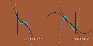
|
|
| |
| |
|
|
|
|
| |
| |
|
|
On 10/18/20 6:10 AM, William F Pokorny wrote:
> On 10/17/20 10:49 PM, Kenneth wrote:
....
>
> We could go a different way for a fix. One which implements the
> previous, unit cube centered, face results by default, but which now
> offers an offset keyword. The offset would let users slide a 0.367 delta
> value range around as fed to the quilt_cubic function. Sort of a left /
> right slider for the posted quilt_cubic curves. (Back to the function's
> curves having meaning...)
>
> Attached is a second image quiltedOptionTwo.png. The left set of 9 is
> the same A to I set. Here it's what users would see at the unit faces
> with the existing implementation (ignoring the noise issue). The offset
> is 0.5 for these. In the right set of 9, I've used an offset of -1.0.
> Many of the faces invert (inside of the pillow) and the results are more
> pillow like.
>
> Is this a better way to go for a fix?
>

I going to use this option as a fix for the true normal version of
quilted in povr - without the offset keyword for now.

Plan is to enable more complicated alternatives as functions. Maybe the
earlier more flexible but less quilted / pillow like alternative as
another true normal pattern at some point.

Attached is an image showing part of the current biscuit.pov scene which
is one commonly run; It's the 'make check' test scene. On the left the
current v3.8 result. In the middle the with the fix. On the right the
difference.

Because the evaluation point drifts around due turbulence, the v3.8
quilted is showing both the issue of varying strengths in the quilting
and partial inversions (sudden changes in intensity along a curve).

Aside: One other subtle issue I should mention with the current and
longstanding code and only partly addressed with the update. Larger,
(especially negative) bump sizes can cause inversions to face the away
from the primary incoming normal for the ray (black areas). This can
always happen, but is more likely with no_bump_scale(1). Yes, it's
possible to add code to prevent this(2), but the current fix is already
adding +6%, give or take, to the run time of biscuit.pov. Plus, this
exposure is more general than quilted.

(1) - Probably a the reason for 0.5 the default bump size. Staying <<1
is more stable.

(2) - My thinking is ideally normal perturbations don't completely
invert the normal. Meaning the major inside/outside surface ray ->
normal relation stays the same (doesn't suddenly act as shadowed).

Bill P.
Post a reply to this message
Attachments:
Download 'qlt_biscuit_v38_to_biscuit.jpg' (116 KB)
Preview of image 'qlt_biscuit_v38_to_biscuit.jpg'
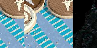
|
|
| |
| |
|
|
|
|
| |
| |
|
|
FYI:

I was just digging around in the source code for the older versions, looking for
some information on normal calculations, and there is a comment that the quilted
normal was written by Dan farmer in 1994.

- BE
Post a reply to this message
|
|
| |
| |
|
|
|
|
| |
| |
|
|
Just so people know, there is no limit to how people will take advantage of your
curiosity and labor.

"Freya" (Joachim) Holmer has a very popular youtube video.
No one can possibly guess where the inspiration for that one came from.

Rodolphe Vaillant

This is not the "March 18" version, but one that was recently updated without
attribution between this past Friday 2025-11-21 and today.

https://rodolphe-vaillant.fr/entry/87/normal-to-an-implicit-surface

Curious update with no email.   We'll see how this one plays out.

"Keep your friends close, keep your enemies closer."
"There is no honor amongst thieves."
Post a reply to this message
|
|
| |
| |
|
|
|
|
| |
| |
|
|
hi,

"Bald Eagle" <cre### [at] netscapenet> wrote:
> Just so people know, there is no limit to how people will take advantage of your
> curiosity and labor.
> ...
> "There is no honor amongst thieves."

imitation is the sincerest form of flattery (that mediocrity can pay to
greatness) ?

(Google says I'm quoting Oscar Wilde)


regards, jr.
Post a reply to this message
|
|
| |
| |
|
|
|
|
| |
| |
|
|
"jr" <cre### [at] gmailcom> wrote:

> imitation is the sincerest form of flattery (that mediocrity can pay to
> greatness) ?


"(you) can resist everything except temptation"  ;)  :P
Post a reply to this message
|
|
| |
| |
|
|
|
|
| |
|
|