|
|
|
|
|
|
| |
| |
|
|
|
|
| |
| |
|
|
Hi(gh)!

After having been inspired by Vahur Krouverk's ancient grass script to
once more take up the Khyberspace project after a six-year lull, I soon
had to realize that Kabul, even Kabul in the 1970s, is much better
documented on the Internet than Herat. So I dug out my ASTER-based
GeoTIFF tiles, more precisely, the PNG conversions I made from them back
then and started to render Kabul basin vistas once more.

Back in 2013 and still with POV-Ray 3.6, I had to lower the elevation
data tiles' original resolution (3600 by 3600) to 2600 by 2600 measuring
points per square degree to get the mesh generated at all...
I supposed that the internal treatment of mesh2 data (ASCII rather than
binary) in POV-Ray 3.6 was responsible for this, so I almost started to
rewrite the relevant sections in the source code...

Obviously, this has been fixed with 3.7, for now rendering works
flawlessly even with the original data resolution! Or is it just because
of my recent RAM upgrade from 16 to 24 GiB?

And, yes, pre-generating the terrain mesh speeds up things dramatically:
from about 1 hour 40 minutes (when calculating the mesh2 together with
the rendering proper) to a mere 12 minutes!

I also think it's time to change the general concept of Khyberspace: as
cartographic data for Afghanistan in the early 1970s are pretty coarse,
I now prefer to start with present-day Afghanistan (minus the war),
blending past, present and even future ("Afghatopia") together, creating
something entirely new!

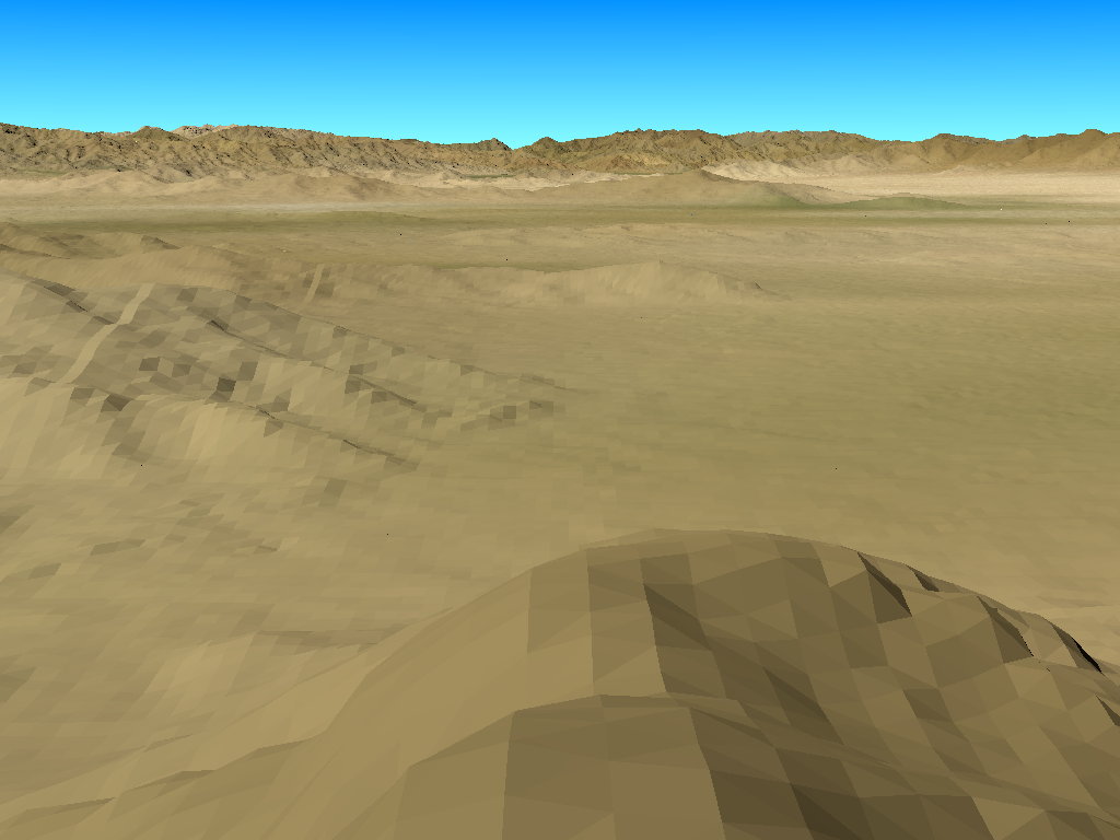
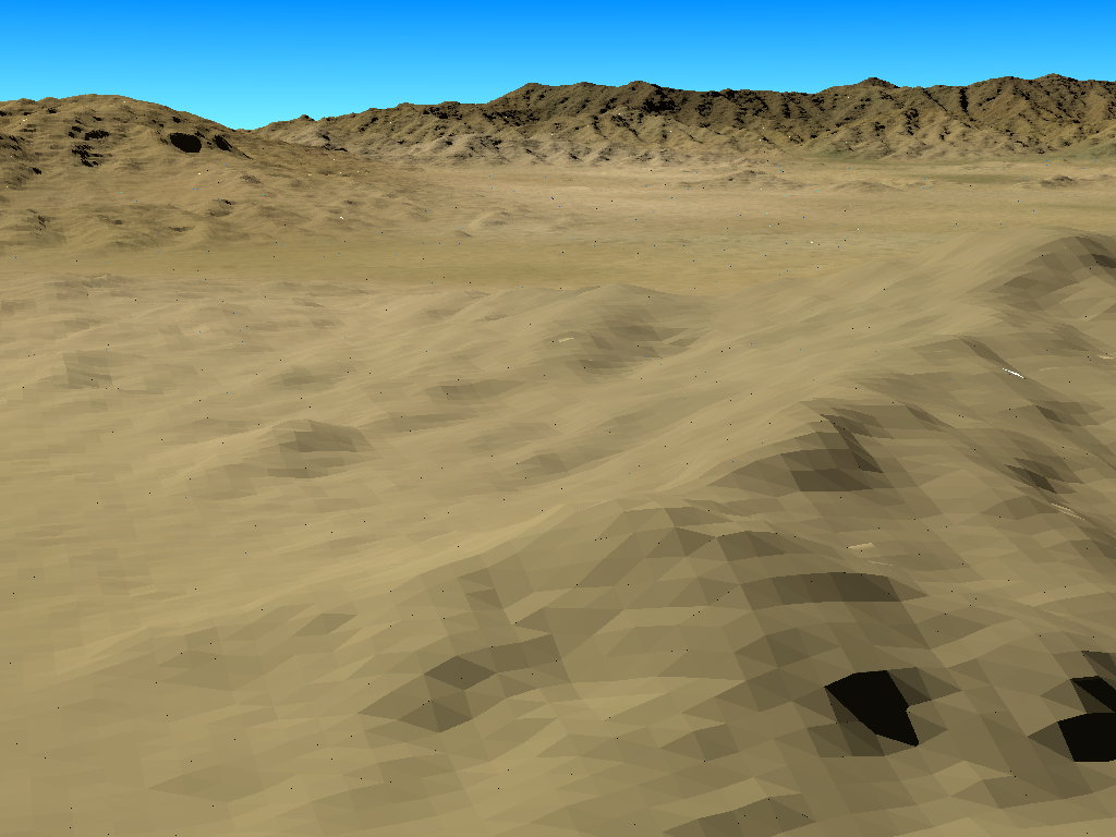
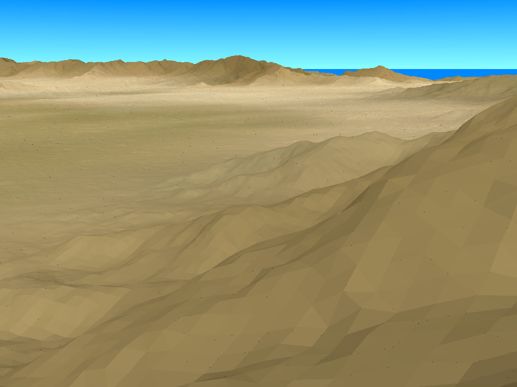
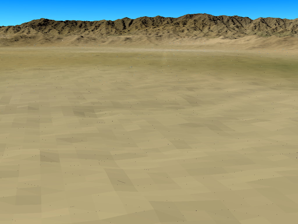
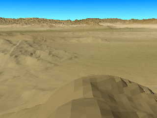
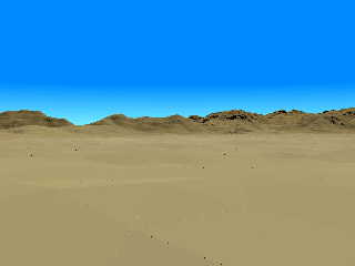
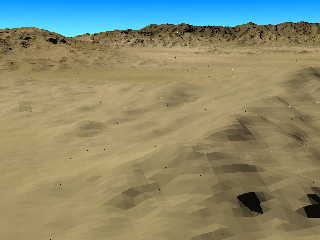
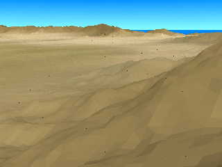
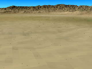
So I started once more rendering some vistas in and around Kabul, three
of them attached here... but this time, I wonder that my old recipe
against dot artifacts which I looked up in a posting from July 2013
(defining the mesh2 vertices close to the origin and moving the whole
mesh2 afterwards) does work with 3.7 only when I do the generating of
the mesh2 within the rendering proper (the time-consuming way as
described here further up), not anymore with a pre-generated mesh2! How
can I fix this?

The first of the attached images has been calculated this way, the other
ones with a pre-generated mesh2 and thus contain those weird dots...

See you in Khyberspace!

Yadgar
Post a reply to this message
Attachments:
Download '2019-11-23 view over kabul and shomali plain from south, take 2 - full mesh2 resolution.jpg' (80 KB)
Download '2019-11-23 view from kabul international airport towards bibi mahru hill and koh-e asmai, take 2 - full mesh2 resolution' (41 KB)
Download '2019-11-23 paghman range from east-southeast, take 2 - full mesh2 resolution.jpg' (108 KB)
Download '2019-11-23 koh-e safi from southwest, take 2 - full mesh2 resolution.jpg' (66 KB)
Download '2019-11-23 approaching kabul international airport from east, take 2 - full mesh2 resolution.jpg' (88 KB)
Preview of image '2019-11-23 view over kabul and shomali plain from south, take 2 - full mesh2 resolution.jpg'
Preview of image '2019-11-23 view from kabul international airport towards bibi mahru hill and koh-e asmai, take 2 - full mesh2 resolution'
Preview of image '2019-11-23 paghman range from east-southeast, take 2 - full mesh2 resolution.jpg'
Preview of image '2019-11-23 koh-e safi from southwest, take 2 - full mesh2 resolution.jpg'
Preview of image '2019-11-23 approaching kabul international airport from east, take 2 - full mesh2 resolution.jpg'
|
|
| |
| |
|
|
|
|
| |
| |
|
|
I suppose you have the digital elevation model, I wouldn't know by looking.
https://pubs.er.usgs.gov/publication/ds130
dem2pov.exe exists, but you probably knew that.

render on
Post a reply to this message
|
|
| |
| |
|
|
|
|
| |
| |
|
|
just some shade trees and an oasis, maybe a waterfall or two, one might have
something .... :)
Post a reply to this message
|
|
| |
| |
|
|
|
|
| |
| |
|
|
Op 23/11/2019 om 22:18 schreef Jörg "Yadgar" Bleimann:
> Hi(gh)!
>
[snip]

> So I started once more rendering some vistas in and around Kabul, three
> of them attached here... but this time, I wonder that my old recipe
> against dot artifacts which I looked up in a posting from July 2013
> (defining the mesh2 vertices close to the origin and moving the whole
> mesh2 afterwards) does work with 3.7 only when I do the generating of
> the mesh2 within the rendering proper (the time-consuming way as
> described here further up), not anymore with a pre-generated mesh2! How
> can I fix this?
>
> The first of the attached images has been calculated this way, the other
> ones with a pre-generated mesh2 and thus contain those weird dots...
>

I shouldn't be too concerned about the dots presently. As Melody also
suggests, once you add objects to the scene, especially in the
foreground, the dots will become invisible or at least inconspicuous.
The foreground texture(s) also will help. All that will be needed
additionally to help hide the triangles of course.

--
Thomas
Post a reply to this message
|
|
| |
| |
|
|
|
|
| |
| |
|
|
Thomas de Groot <tho### [at] degroot org> wrote:
> I shouldn't be too concerned about the dots presently. As Melody also
> suggests, once you add objects to the scene, especially in the
> foreground, the dots will become invisible or at least inconspicuous.
> The foreground texture(s) also will help. All that will be needed
> additionally to help hide the triangles of course.
>
> --
> Thomas
calculate normals of each point, respective to all adjacent faces and use smooth
triangles, lines go bye bye. iterate verts and compare to each triangle face.
#macro normal_vector(A,B,C)
#local result = vcross(C-B,A-B);
result
// 1
// |
// 2__ 3 vz points at you (neg) unless reverse y like pov, then
//
// 2__ 3
// |
// 1
#end
#macro FastNorms77(sw)
// set norms based on ALL adjacent faces-lots of verts means lots of time
#local i=0;
#while (i<NumVertices)
#local nrm = <0,0,0>;
#local j = 0;
#while (j<NumFaces)
#if ((i = Face_Arr[j].x)|(i = Face_Arr[j].y)|(i = Face_Arr[j].z))
#local norm =
normal_vector(V_vec_Arr[Face_Arr[j].x],V_vec_Arr[Face_Arr[j].y],V_vec_Arr[Face_Arr[j].z]);
#local nrm = vnormalize(nrm+vnormalize(norm));
#end
#local j=j+1;
#end // Faces
#declare N_vec_Arr[i] = nrm;
#local i=i+1;
#if (sw) // Progress on/off
#if (mod(100*i/NumVertices,20)<0.1)
#debug concat("Checking Normals >
",str(int(100*i/NumVertices),5,1),"%\n")
#end
#end
#end // Verts
#end org> wrote:
> I shouldn't be too concerned about the dots presently. As Melody also
> suggests, once you add objects to the scene, especially in the
> foreground, the dots will become invisible or at least inconspicuous.
> The foreground texture(s) also will help. All that will be needed
> additionally to help hide the triangles of course.
>
> --
> Thomas
calculate normals of each point, respective to all adjacent faces and use smooth
triangles, lines go bye bye. iterate verts and compare to each triangle face.
#macro normal_vector(A,B,C)
#local result = vcross(C-B,A-B);
result
// 1
// |
// 2__ 3 vz points at you (neg) unless reverse y like pov, then
//
// 2__ 3
// |
// 1
#end
#macro FastNorms77(sw)
// set norms based on ALL adjacent faces-lots of verts means lots of time
#local i=0;
#while (i<NumVertices)
#local nrm = <0,0,0>;
#local j = 0;
#while (j<NumFaces)
#if ((i = Face_Arr[j].x)|(i = Face_Arr[j].y)|(i = Face_Arr[j].z))
#local norm =
normal_vector(V_vec_Arr[Face_Arr[j].x],V_vec_Arr[Face_Arr[j].y],V_vec_Arr[Face_Arr[j].z]);
#local nrm = vnormalize(nrm+vnormalize(norm));
#end
#local j=j+1;
#end // Faces
#declare N_vec_Arr[i] = nrm;
#local i=i+1;
#if (sw) // Progress on/off
#if (mod(100*i/NumVertices,20)<0.1)
#debug concat("Checking Normals >
",str(int(100*i/NumVertices),5,1),"%\n")
#end
#end
#end // Verts
#end
Post a reply to this message
|
|
| |
| |
|
|
|
|
| |
| |
|
|
Op 24/11/2019 om 11:21 schreef Melody:
> Thomas de Groot <tho### [at] degrootorg> wrote:
>
>> I shouldn't be too concerned about the dots presently. As Melody also
>> suggests, once you add objects to the scene, especially in the
>> foreground, the dots will become invisible or at least inconspicuous.
>> The foreground texture(s) also will help. All that will be needed
>> additionally to help hide the triangles of course.
>>
>> --
>> Thomas
>
> calculate normals of each point, respective to all adjacent faces and use smooth
> triangles, lines go bye bye. iterate verts and compare to each triangle face.
>
>
> #macro normal_vector(A,B,C)
>   #local result = vcross(C-B,A-B);
>   result
>   // 1
>   // |
>   // 2__ 3 vz points at you (neg) unless reverse y like pov, then
>   //
>   // 2__ 3
>   // |
>   // 1
> #end
>
> #macro FastNorms77(sw)
>    // set norms based on ALL adjacent faces-lots of verts means lots of time
>    #local i=0;
>    #while (i<NumVertices)
>      #local nrm = <0,0,0>;
>      #local j = 0;
>      #while (j<NumFaces)
>        #if ((i = Face_Arr[j].x)|(i = Face_Arr[j].y)|(i = Face_Arr[j].z))
>          #local norm =
>
normal_vector(V_vec_Arr[Face_Arr[j].x],V_vec_Arr[Face_Arr[j].y],V_vec_Arr[Face_Arr[j].z]);
>          #local nrm = vnormalize(nrm+vnormalize(norm));
>        #end
>        #local j=j+1;
>      #end // Faces
>      #declare N_vec_Arr[i] = nrm;
>      #local i=i+1;
>      #if (sw)  // Progress on/off
>          #if (mod(100*i/NumVertices,20)<0.1)
>            #debug concat("Checking Normals  >
> ",str(int(100*i/NumVertices),5,1),"%\n")
>         #end
>      #end
>    #end // Verts
> #end
>
>
>
>
I think smooth triangles are already in use in this scene and lines
appear because of the height_field size close to the camera. However,
your macros are worth to be tried out here, I guess, to see if it
improves the image.

--
Thomas
Post a reply to this message
|
|
| |
| |
|
|
|
|
| |
| |
|
|
the scene looks like a billion points,
so I would say isolate local points for mesh of smooth triangles.

I might have more ideas when I have time to look that this Grand Canyon DEM
used here. smooth smooth.

but height_field I recall seeing triangles, but there's a smoothing command?
I dont really remember exactly.
Post a reply to this message
Attachments:
Download 'rebel_snowspeeder.jpg' (103 KB)
Preview of image 'rebel_snowspeeder.jpg'

|
|
| |
| |
|
|
|
|
| |
| |
|
|
Hi(gh)!

On 24.11.19 12:47, Thomas de Groot wrote:

> I think smooth triangles are already in use in this scene

No, they are not... I will try Melody's macros, though its gonna be tough!

See you in Khyberspace!

Yadgar
Post a reply to this message
|
|
| |
| |
|
|
|
|
| |
| |
|
|
Hi(gh)!

On 24.11.19 14:23, Jörg "Yadgar" Bleimann wrote:

> No, they are not... I will try Melody's macros, though its gonna be tough!

Perhaps too tough for me... I don't have the faintest clue how to
integrate the output of these functions (i. e. N_vec_Arr[])! Where shall
I invoke the macro - inside the mesh2 object?

See you in Khyberspace!

Yadgar
Post a reply to this message
|
|
| |
| |
|
|
|
|
| |
| |
|
|
Hi(gh)!

On 24.11.19 11:21, Melody wrote:
>
> calculate normals of each point, respective to all adjacent faces and use smooth
> triangles, lines go bye bye. iterate verts and compare to each triangle face.
>
>
> #macro normal_vector(A,B,C)
>   #local result = vcross(C-B,A-B);
>   result
>   // 1
>   // |
>   // 2__ 3 vz points at you (neg) unless reverse y like pov, then
>   //
>   // 2__ 3
>   // |
>   // 1
> #end
>
> #macro FastNorms77(sw)
>    // set norms based on ALL adjacent faces-lots of verts means lots of time
>    #local i=0;
>    #while (i<NumVertices)
>      #local nrm = <0,0,0>;
>      #local j = 0;
>      #while (j<NumFaces)
>        #if ((i = Face_Arr[j].x)|(i = Face_Arr[j].y)|(i = Face_Arr[j].z))
>          #local norm =
>
normal_vector(V_vec_Arr[Face_Arr[j].x],V_vec_Arr[Face_Arr[j].y],V_vec_Arr[Face_Arr[j].z]);
>          #local nrm = vnormalize(nrm+vnormalize(norm));
>        #end
>        #local j=j+1;
>      #end // Faces
>      #declare N_vec_Arr[i] = nrm;
>      #local i=i+1;
>      #if (sw)  // Progress on/off
>          #if (mod(100*i/NumVertices,20)<0.1)
>            #debug concat("Checking Normals  >
> ",str(int(100*i/NumVertices),5,1),"%\n")
>         #end
>      #end
>    #end // Verts
> #end
>
>
>
>

Where did you define Face_Arr and V_vec_Arr?

See you in Khyberspace!

Yadgar
Post a reply to this message
|
|
| |
| |
|
|
|
|
| |
| |
|
|
> Perhaps too tough for me... I don't have the faintest clue how to
> integrate the output of these functions (i. e. N_vec_Arr[])! Where shall
> I invoke the macro - inside the mesh2 object?

Once you got verts and faces set, just call FastNorms77(1)
It simply defines your Normals. Then you are ready to define a mesh.

OK,so.
you might know NumVertices. if not, you guess at first, or you could make
function to count them.

here we are guessing, later we count and reset NumVertices.
basically stacks*slices, or some known dimensions.
over estimate if guessing, don't under estimate.

initially:
   #declare NumVertices = stacks*slices;

   #declare V_vec_Arr=array[NumVertices]
   #declare N_vec_Arr=array[NumVertices]
   #declare UV_vec_Arr=array[NumVertices]
   #declare NumEdges = 0;
   #declare Edge_Arr=array[NumVertices]
   #declare NumFaces = 0;
   #declare Face_Arr=array[NumVertices*2]
   cr() echof(NumVertices) echo(" Allocated")
(see echo.inc - cr() =carriage return, #debug float, #debug "string")
then you can see your allocated estimate, to see if later it looks too big, etc.

NumFaces might average twice the NumVertices.

legend
V = Vertices
N = Normals
UV = UV (for mapping)

NEXT
Define Vertices
V_vec_Arr[i] = <,,>; // (some 3d point)

NEXT
NumFaces are counted and set, when faces are defined.
<1,2,3> integers in the range of NumVertices

hope this helps,
Melody
Post a reply to this message
|
|
| |
| |
|
|
|
|
| |
| |
|
|
write the file and save, could be a plan, or
V N V N V N
#macro SmoothTriangles(c)
     #local i=0;
     mesh {
        #while (i<NumFaces)
             smooth_triangle {
               V_vec_Arr[Face_Arr[i].x]
               N_vec_Arr[Face_Arr[i].x]
               V_vec_Arr[Face_Arr[i].y]
               N_vec_Arr[Face_Arr[i].y]
               V_vec_Arr[Face_Arr[i].z]
               N_vec_Arr[Face_Arr[i].z]
             }
           #local i=i+1;
        #end
     }
#end

got everything defined? mesh2 is map able.
#macro _Surface()
   mesh2 {
      #local i = 0;
      vertex_vectors {
         NumVertices
         #while (i<NumVertices)
            V_vec_Arr[i]
            #local i = i+1;
         #end
      }
      #local i = 0;
      normal_vectors {
         NumVertices
         #while (i<NumVertices)
            N_vec_Arr[i]
            #local i = i+1;
         #end
      }
      #local i = 0;
      uv_vectors {
         NumVertices
         #while (i<NumVertices)
            UV_vec_Arr[i]
            #local i = i+1;
         #end
      }
      #local i = 0;
        echo("\nNum _Surface() Faces ") echoi(NumFaces)
      face_indices {
         NumFaces
         #local i = 0;
         #while (i<NumFaces)
            Face_Arr[i]
            #local i = i+1;
         #end
      }
}
#end
Post a reply to this message
|
|
| |
| |
|
|
|
|
| |
| |
|
|
now I remember, rebel_snowspeeder
was defined by an image map of the Grand Canyon. all u do i this:
height_field { tga "gce.tga" smooth
  scale <1000, 100, 1000>*10
  translate <-500, -100,0>*10

  texture {
    pigment { color white }
    finish { ambient 0.6 reflection 0 diffuse 0.4 }
  }
}

DEM2POV v1.2a

Converts USGS Digital Elevation Model data files to tga height-field for
POV raytracer. converted W. D. Kirby, 30 mar 96. hacked from dem2xyz.c
18 apr 95. converts 3 arc second to lat/long, sol katz, mar. 94. added
sampling and cutting to size, sol katz, apr 94. changed the calculation
of start position in sampling code, sol katz, jan 95.

here's an png
Post a reply to this message
Attachments:
Download 'gce.png' (1317 KB)
Preview of image 'gce.png'

|
|
| |
| |
|
|
|
|
| |
| |
|
|
=?UTF-8?Q?J=c3=b6rg_=22Yadgar=22_Bleimann?= <yaz### [at] gmxde> wrote:
> Where shall I invoke the macro - inside the mesh2 object?

for some reason the assumption was a mesh, then Thomas mentioned height_field.
so I did some digging.

Digital elevation was not confirmed; we got on meshes.
With the mesh code, you can make anything u have points for,
or for anything you can logic calculating.
Post a reply to this message
|
|
| |
| |
|
|
|
|
| |
| |
|
|
https://www2.jpl.nasa.gov/srtm/cbanddataproducts.html
"If you want to download SRTM data, those data are available at the US
Geological Survey's EROS Data Center for download. "
supposed to be here,
http://srtm.usgs.gov/index.html

I cant get in.
srtm.usgs.gov’s server IP address could not be found.


http://www.webgis.com/terr_us1deg.html
has dem files - 2 tests fail for same reason, this sucks
dem2pov.exe
CALCULATED column Count 1 != HEADER 350
       will use SMALLER column Count
number of rows 1, number of columns 1

1x1 is nothing

post dem file downloads, if anyone knows.
Post a reply to this message
|
|
| |
| |
|
|
|
|
| |
| |
|
|
for a dem file that works, (cant find any on the net.)
use the vertical scale input of 20 for this image.
1 = shades of only green.

number of rows 1201, number of columns 1201
Enter 0 for all,  1 for samples,  2 for subset : 0
Height-field type (0) Actual heights (1) Normalized : 0
Enter a vertical scaling factor : 20
Enter elevation bias: 0
Enter default elevation (final output units) : 1 (I dont know this one)

The last interactive input defines a default elevation in the output
units to be used for those pixel points where DEM data are not
available. This is useful for eliminating sharp changes at the
height-field edges where sparse data situations may occur.

even still ... lol wth?
Post a reply to this message
Attachments:
Download 'gce.jpg' (654 KB)
Preview of image 'gce.jpg'

|
|
| |
| |
|
|
|
|
| |
| |
|
|
Le 2019-11-24 à 07:09, Melody a écrit :
> the scene looks like a billion points,
> so I would say isolate local points for mesh of smooth triangles.
>
> I might have more ideas when I have time to look that this Grand Canyon DEM
> used here. smooth smooth.
>
> but height_field I recall seeing triangles, but there's a smoothing command?
> I dont really remember exactly.
>

hight_field{DefinitionOfHightField   smooth   AnyTransformAndTecture}
Post a reply to this message
|
|
| |
| |
|
|
|
|
| |
| |
|
|
Hi(gh)!

On 25.11.19 18:29, Alain Martel wrote:

> hight_field{DefinitionOfHightField   smooth   AnyTransformAndTecture}

It's not a heightfield, but a spherical (i. e. following Earth's
curvature) mesh2 derived from a PNG, which in turn has been generated
from an ASCII data matrix!

See you in Khyberspace!

Yadgar
Post a reply to this message
|
|
| |
| |
|
|
|
|
| |
|
|