|
|
|
|
|
|
| |
| |
|
|
|
|
| |
| |
|
|
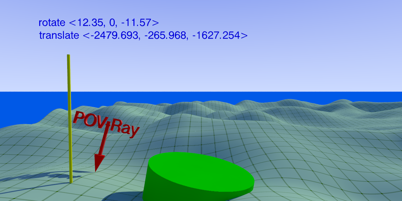
See my latest post in p.t.general. The yellow rod is situated about -200
pov units from the trace arrow.

--
Thomas
Post a reply to this message
Attachments:
Download 'islaytest.png' (368 KB)
Preview of image 'islaytest.png'
|
|
| |
| |
|
|
|
|
| |
| |
|
|
Thomas de Groot <tho### [at] degroot org> wrote:
> See my latest post in p.t.general. The yellow rod is situated about -200
> pov units from the trace arrow.
>
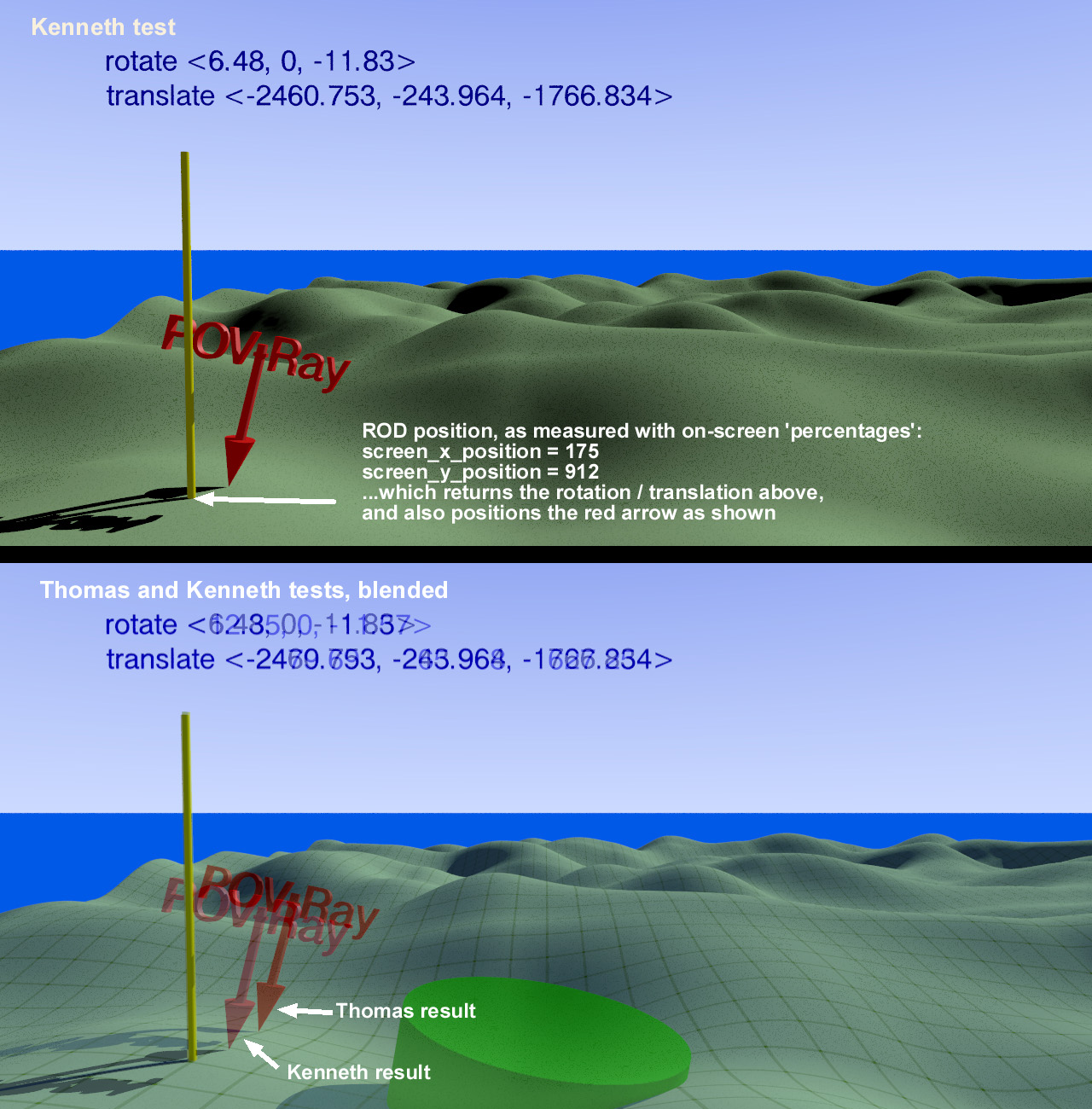
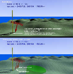
I got side-tracked by a surprising and different problem, concerning your test
image. I rendered the same view (as close as I could get-- using CamAng of 80),
and found that you and I are indeed getting different results(!) I have no idea
what the reason might be. My 2nd 'blended' image shows that we are at least
rendering the same view, and with the yellow rod in the same place. Why our red
arrows don't match is a mystery! Very strange. (Unless we are somehow using
different methodologies?? I doubt that, though.)
For the yellow rod in the position it's currently in, did you get the same
screen_x_position and screen_y_position values that I did (or nearly so)?
This is a mystery that we definitely need to solve ;-) org> wrote:
> See my latest post in p.t.general. The yellow rod is situated about -200
> pov units from the trace arrow.
>
I got side-tracked by a surprising and different problem, concerning your test
image. I rendered the same view (as close as I could get-- using CamAng of 80),
and found that you and I are indeed getting different results(!) I have no idea
what the reason might be. My 2nd 'blended' image shows that we are at least
rendering the same view, and with the yellow rod in the same place. Why our red
arrows don't match is a mystery! Very strange. (Unless we are somehow using
different methodologies?? I doubt that, though.)
For the yellow rod in the position it's currently in, did you get the same
screen_x_position and screen_y_position values that I did (or nearly so)?
This is a mystery that we definitely need to solve ;-)
Post a reply to this message
Attachments:
Download 'islaytest_1_kw.jpg' (388 KB)
Preview of image 'islaytest_1_kw.jpg'
|
|
| |
| |
|
|
|
|
| |
| |
|
|
On 28-9-2018 11:51, Kenneth wrote:
> Thomas de Groot <tho### [at] degrootorg> wrote:
>> See my latest post in p.t.general. The yellow rod is situated about -200
>> pov units from the trace arrow.
>>
>
> I got side-tracked by a surprising and different problem, concerning your test
> image. I rendered the same view (as close as I could get-- using CamAng of 80),
> and found that you and I are indeed getting different results(!) I have no idea
> what the reason might be. My 2nd 'blended' image shows that we are at least
> rendering the same view, and with the yellow rod in the same place. Why our red
> arrows don't match is a mystery! Very strange. (Unless we are somehow using
> different methodologies?? I doubt that, though.)
>
> For the yellow rod in the position it's currently in, did you get the same
> screen_x_position and screen_y_position values that I did (or nearly so)?
>
> This is a mystery that we definitely need to solve ;-)
>
>

My bad, as I misplaced the rod by one square :-/

The yellow rod is placed at: <202, 884> (screen percent) ==> <-2479.693,
-265.968, -1757.000> (forget the Y which is not relevant here)

At <202, 884> percent, I get an arrow position of: <-2479.693, -265.968,
-1627.254>

I have a hunch that you will get about the same. Forget about the 200
pov units. It is less and not so 'rounded' as I thought (about 130 instead).

--
Thomas
Post a reply to this message
|
|
| |
| |
|
|
|
|
| |
| |
|
|
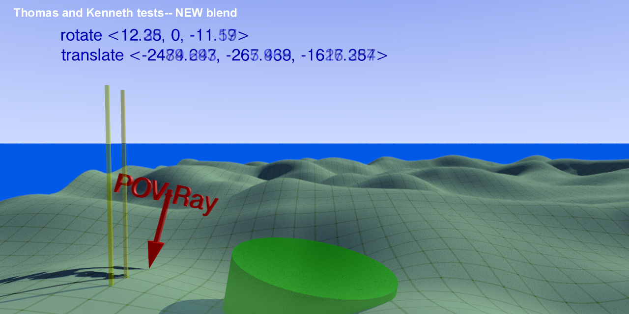
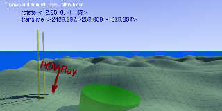
Thomas de Groot <tho### [at] degrootorg> wrote:

>
> My bad, as I misplaced the rod by one square :-/
>

Ha! Tt is always a relief when a so-called 'problem' has a simple solution :-P

At some point, I hope to find a good solution to the arrow-offset problem
itself.
Post a reply to this message
Attachments:
Download 'islaytest_2_kw.jpg' (199 KB)
Preview of image 'islaytest_2_kw.jpg'
|
|
| |
| |
|
|
|
|
| |
| |
|
|
On 28-9-2018 21:28, Kenneth wrote:
> Thomas de Groot <tho### [at] degrootorg> wrote:
>
>>
>> My bad, as I misplaced the rod by one square :-/
>>
>
> Ha! Tt is always a relief when a so-called 'problem' has a simple solution :-P

Yes indeed.

>
> At some point, I hope to find a good solution to the arrow-offset problem
> itself.
>

I am twisting my brains in every direction to understand this. Beyond my
abilities I am afraid.

--
Thomas
Post a reply to this message
|
|
| |
| |
|
|
|
|
| |
| |
|
|
On 29-9-2018 8:31, Thomas de Groot wrote:
> On 28-9-2018 21:28, Kenneth wrote:
>> Thomas de Groot <tho### [at] degrootorg> wrote:
>>
>>>
>>> My bad, as I misplaced the rod by one square :-/
>>>
>>
>> Ha! Tt is always a relief when a so-called 'problem' has a simple
>> solution :-P
>
> Yes indeed.
>
>>
>> At some point, I hope to find a good solution to the arrow-offset problem
>> itself.
>>
>
> I am twisting my brains in every direction to understand this. Beyond my
> abilities I am afraid.
>

...looking more closely at the macro code, I wonder if something is
missing to the dir_xy parameter, or to the dir_y parameter more
probably, as this last one controls the eventual z-location...

--
Thomas
Post a reply to this message
|
|
| |
| |
|
|
|
|
| |
| |
|
|
Thomas de Groot <tho### [at] degrootorg> wrote:
>
> ...looking more closely at the macro code, I wonder if something is
> missing to the dir_xy parameter, or to the dir_y parameter more
> probably, as this last one controls the eventual z-location...
>

I agree.

There is a small multiplier value in both equations -- .01 -- that *seems* to
relate to screen percentages (just my guess). I.e., 1-percent. Changing those
even slightly (to .011 for example) shifts the resulting arrow location.
Currently, the values are constants, but I wonder if they need to dynamically
change as the camera angle changes?

I have to admit that some of Norbert's math trickery is beyond me. At the same
time, his code is an instructive lesson in how to use POV-Ray's built-in math
constructs and keywords, and what effects they have. Hopefully, I will learn
some new things-- given enough time!
Post a reply to this message
|
|
| |
| |
|
|
|
|
| |
| |
|
|
I have actually had a little bit of time to look at this code in more detail and
shift it over to my camera view frustum scene --- whereupon it doesn't see the
SURFACE unless the plane is included, and then that's the only thing it sees...

But I do agree, after back-tracking through the code, that dir_xy, which is used
in the trace () call has a high probability of being the culprit.

Having said that, the whole manner in which this macro works with vaxis_rotate
is a bit hard to follow, and it may be easier to start from first principles.


I think that if you look at the screen.inc code, you'll see that all you're
doing is using normalized coordinates in screen space.
If you just extend that vector, you "reach out" into the scene past z=1.
(assuming a default camera)
This ought to be a matter of the same simple trig, with no hard-to-follow (and
verify by hand) rotating vectors around axes.
So more than half the work is already done.
{Just erase all the stuff about object dimensions and offsets, etc. since we're
only working with a single point.}

I propose a new format for the scene - have three independent code blocks,
chosen with a switch/case/break/end block.

0.  The current Norbert Kern / Kenneth Walker code
1.  a method which is a simple extension of screen.inc object placement
2.  a method which uses a matrix

In this way they can be wrapped in a loop and executed sequentially in the same
scene run, to compare the results of the different methods of calculation.

I'm suggesting this because working it out by method 1 ought to help unravel
what's going on with method 0, and method 2 will just be points for style   :)

I have to do a bunch of IRL stuff today - but hopefully I will be able to return
to this in the near future and have some code snippets of my own to offer.
Post a reply to this message
|
|
| |
| |
|
|
|
|
| |
| |
|
|
On 30-9-2018 15:33, Bald Eagle wrote:
> I have actually had a little bit of time to look at this code in more detail and
> shift it over to my camera view frustum scene --- whereupon it doesn't see the
> SURFACE unless the plane is included, and then that's the only thing it sees...

???

>
> But I do agree, after back-tracking through the code, that dir_xy, which is used
> in the trace () call has a high probability of being the culprit.
>
> Having said that, the whole manner in which this macro works with vaxis_rotate
> is a bit hard to follow, and it may be easier to start from first principles.
>

I must admit that I have major difficulties with vnormalize and vcross.
Somehow I achieve to understand vaxis_rotate more intuitively :-/ but
the whole code is bursting my brains.

>
> I think that if you look at the screen.inc code, you'll see that all you're
> doing is using normalized coordinates in screen space.
> If you just extend that vector, you "reach out" into the scene past z=1.
> (assuming a default camera)
> This ought to be a matter of the same simple trig, with no hard-to-follow (and
> verify by hand) rotating vectors around axes.
> So more than half the work is already done.
> {Just erase all the stuff about object dimensions and offsets, etc. since we're
> only working with a single point.}

This is a highly interesting suggestion! I don't know if I can manage it
but I am confident that Kenneth can. However, I am going to get my hands
dirty nonetheless.

>
> I propose a new format for the scene - have three independent code blocks,
> chosen with a switch/case/break/end block.
>
> 0.  The current Norbert Kern / Kenneth Walker code
> 1.  a method which is a simple extension of screen.inc object placement
> 2.  a method which uses a matrix
>
> In this way they can be wrapped in a loop and executed sequentially in the same
> scene run, to compare the results of the different methods of calculation.
>

Excellent suggestion.

> I'm suggesting this because working it out by method 1 ought to help unravel
> what's going on with method 0, and method 2 will just be points for style   :)
>
> I have to do a bunch of IRL stuff today - but hopefully I will be able to return
> to this in the near future and have some code snippets of my own to offer.
>

Thanks again!

--
Thomas
Post a reply to this message
|
|
| |
| |
|
|
|
|
| |
| |
|
|
Am 01.10.2018 um 08:52 schrieb Thomas de Groot:

> I must admit that I have major difficulties with vnormalize and vcross.

What's difficult aout `vnormalize`? It simply trims (or stretches) a
vector to a length of 1 while keeping the direction. No magic there.

What `vcross` does is a bit more complex, I give you that; but normally
it is simply used to compute a vector perpendicular to two others (with
proper handedness; e.g. vcross(x,y) returs z), and is trimmed to unit
size using vnormalize (unless the two input vectors are known to be
perpendicular and of unit length).
Post a reply to this message
|
|
| |
| |
|
|
|
|
| |
| |
|
|
On 1-10-2018 14:24, clipka wrote:
> Am 01.10.2018 um 08:52 schrieb Thomas de Groot:
>
>> I must admit that I have major difficulties with vnormalize and vcross.
>
> What's difficult aout `vnormalize`? It simply trims (or stretches) a
> vector to a length of 1 while keeping the direction. No magic there.
>
> What `vcross` does is a bit more complex, I give you that; but normally
> it is simply used to compute a vector perpendicular to two others (with
> proper handedness; e.g. vcross(x,y) returs z), and is trimmed to unit
> size using vnormalize (unless the two input vectors are known to be
> perpendicular and of unit length).
>

Yes indeed, and the Lohmüllers' site is graphically explicit, but I have
difficulty to understand the "why" of such use in most cases.

--
Thomas
Post a reply to this message
|
|
| |
| |
|
|
|
|
| |
| |
|
|
Thomas de Groot <tho### [at] degrootorg> wrote:

>
> I must admit that I have major difficulties with vnormalize and vcross.
> Somehow I achieve to understand vaxis_rotate more intuitively :-/ but
> the whole code is bursting my brains.
>
[snip]
> ...but I am confident that Kenneth can.

Uh, don't be so sure  :-P

I'm in the same boat as you-- it's vcross and vaxis_rotate that give me the
chills. *Someday*, with enough concentrated thinking, I'll have one of those
'Eureka' moments. Surely!! (?)

But I just discovered something in Norbert's core math code that is of interest
(in a small way): Until now, I've been thinking that the arrow-offset problem is
*somehow* related to his initial cam_z equation-- specifically the
tan(radians(cam_ang*0.5)  part-- because of the use of  tan  itself. (As an
angle approaches 90, tan(90) approaches infinity, which seems problematic. But
then again, his tan equation is working on only HALF the given angle-- so
tan(90) would never happen anyway.) BTW, it's not clear to me why he specified
radians rather than degrees, as a camera angle is specified in degrees(?), or
something similar.

HOWEVER... I've been experimenting with the cam_z equation itself-- and found
that no matter what I do to it, it has no effect on the arrow position, or on
anything else in the scene(!). I even commented-out the equation, and
substituted some wildly-different integer values just for kicks... again with no
effect. I EVENTUALLY realized that cam_z is actually used only once, in cam_dir.
And cam_dir isn't used at all!

I have no excuse for not seeing this until now. :-(

So, cam_z and cam_dir can be erased from the code, to make it a bit simpler to
examine.
Post a reply to this message
|
|
| |
| |
|
|
|
|
| |
| |
|
|
On 2-10-2018 9:40, Kenneth wrote:
> Thomas de Groot <tho### [at] degrootorg> wrote:
>
>>
>> I must admit that I have major difficulties with vnormalize and vcross.
>> Somehow I achieve to understand vaxis_rotate more intuitively :-/ but
>> the whole code is bursting my brains.
>>
> [snip]
>> ...but I am confident that Kenneth can.
>
> Uh, don't be so sure  :-P
>
> I'm in the same boat as you-- it's vcross and vaxis_rotate that give me the
> chills. *Someday*, with enough concentrated thinking, I'll have one of those
> 'Eureka' moments. Surely!! (?)

Yeah... I have not too much problems with vaxis_rotate as I can
understand and visualise the purpose of that in the macro. However, I
scratch my head about the others.

>
> But I just discovered something in Norbert's core math code that is of interest
> (in a small way): Until now, I've been thinking that the arrow-offset problem is
> *somehow* related to his initial cam_z equation-- specifically the
> tan(radians(cam_ang*0.5)  part-- because of the use of  tan  itself. (As an
> angle approaches 90, tan(90) approaches infinity, which seems problematic. But
> then again, his tan equation is working on only HALF the given angle-- so
> tan(90) would never happen anyway.) BTW, it's not clear to me why he specified
> radians rather than degrees, as a camera angle is specified in degrees(?), or
> something similar.
>
> HOWEVER... I've been experimenting with the cam_z equation itself-- and found
> that no matter what I do to it, it has no effect on the arrow position, or on
> anything else in the scene(!). I even commented-out the equation, and
> substituted some wildly-different integer values just for kicks... again with no
> effect. I EVENTUALLY realized that cam_z is actually used only once, in cam_dir.
> And cam_dir isn't used at all!
>
> I have no excuse for not seeing this until now. :-(
>
> So, cam_z and cam_dir can be erased from the code, to make it a bit simpler to
> examine.
>

I have been wondering also about those parameters. I had assumed that
cam_dir was supposed to be the value for the direction parameter in the
camera block. Putting cam_dir there does not do anything vital, so maybe
it is some obsolete leftover from earlier versions? Puzzling, to say the
least.

I agree with you about the radians. There seems to be no need for them
but if cam_z is not used, I don't worry :-)

--
Thomas
Post a reply to this message
|
|
| |
| |
|
|
|
|
| |
| |
|
|
> BTW, it's not clear to me why he specified
> > radians rather than degrees, as a camera angle is specified in degrees(?), or
> > something similar.
> >

> I agree with you about the radians. There seems to be no need for them
> but if cam_z is not used, I don't worry :-)

The angle IS in degrees, but tan () acts on radians.
That's why it needs to get converted to radians first, before performing the
tan() function.
Post a reply to this message
|
|
| |
| |
|
|
|
|
| |
| |
|
|
Am 02.10.2018 um 09:40 schrieb Kenneth:

> HOWEVER... I've been experimenting with the cam_z equation itself-- and found
> that no matter what I do to it, it has no effect on the arrow position, or on
> anything else in the scene(!). I even commented-out the equation, and
> substituted some wildly-different integer values just for kicks... again with no
> effect. I EVENTUALLY realized that cam_z is actually used only once, in cam_dir.
> And cam_dir isn't used at all!
>
> I have no excuse for not seeing this until now. :-(
>
> So, cam_z and cam_dir can be erased from the code, to make it a bit simpler to
> examine.

Or, maybe that's actually the problem?

A macro that tries to probe where a particular pixel's ray hits the
scene must know - and process - /something/ about the camera opening angle.
Post a reply to this message
|
|
| |
| |
|
|
|
|
| |
| |
|
|
clipka <ano### [at] anonymousorg> wrote:

> Or, maybe that's actually the problem?

He's just not seeing it embedded in
transform{TEXT_OBJECT_TRANSFORM}
Post a reply to this message
|
|
| |
| |
|
|
|
|
| |
| |
|
|
"Bald Eagle" <cre### [at] netscapenet> wrote:
> clipka <ano### [at] anonymousorg> wrote:
>
> > Or, maybe that's actually the problem?
>
> He's just not seeing it embedded in
> transform{TEXT_OBJECT_TRANSFORM}


So, I've just been dabbling with this in the odd 5-10 minute blocks of free time
that I have, and trying to see what I did with modeling the camera's view
frustum.

Let's suppose we're using the default camera, with the camera at the origin, the
"canvas"/image plane at z=1, right x, up y, sky, y, direction z, look_at z

If you're going to select pixels, then you want to translate those values so
that you get the +/- 0.5 range for x and y, with the center being <0,0>

Just divide the pixel value by the width and subtract 0.5 to give a range of
-0.5 to 0.5

Do the same for y and height, and flip the sign

Then to project that point "out" into the 3D scene, you just multiply all those
values by the z value (returned by trace() )
Because similar triangles.


This is not the hard part - the hard part is doing this when the basis vectors
are different - when the camera and look_at values, etc aren't axis-aligned.


So for envisioning what to do:
1. Take the scene's camera values and rotate everything so that it's in the
"default" frame.   (more to do if there's shear, etc.)
2. Do the simple math.
3. Rotate everything back by doing exactly the opposite of what you did in step
1.


And this is where I think the transform matrix approach will really shine.

I just need enough uninterrupted round-tuits to get oriented and forge far
enough ahead.

[highly] Suggested reading:
http://www.scratchapixel.com/lessons/3d-basic-rendering/computing-pixel-coordinates-of-3d-point/mathematics-computing-2
d-coordinates-of-3d-points
Post a reply to this message
|
|
| |
| |
|
|
|
|
| |
| |
|
|
"Bald Eagle" <cre### [at] netscapenet> wrote:

[Kenneth wrote:}
> > > So, cam_z and cam_dir can be erased from the code, to make it a bit
> > > simpler to examine.

[Clipka wrote:]
> > Or, maybe that's actually the problem?
> >
> > A macro that tries to probe where a particular pixel's ray hits the
> > scene must know - and process - /something/ about the camera opening angle.
>
> He's just not seeing it embedded in
> transform{TEXT_OBJECT_TRANSFORM}

Do you mean that Clipka's observation is already 'included' in that TEXT OBJECT
matrix in some way? Although I surely don't grasp that, it's quite interesting.
And the matrix is used ONLY for the text objects, not for the arrow placement
(unless all the ingredients in the matrix are also used in another form for the
arrow?) Sorry if I'm not making clear sense; the whole concept is quite fuzzy to
me at the moment.

BTW, apologies for not yet commenting on your code analysis; I'm slowly
digesting it all ;-)
Post a reply to this message
|
|
| |
| |
|
|
|
|
| |
| |
|
|
"Bald Eagle" <cre### [at] netscapenet> wrote:
> > BTW, it's not clear to me why he specified radians rather than degrees, as
> > a camera angle is specified in degrees(?), or something similar.
> > >
>
>
> The angle IS in degrees, but tan () acts on radians.
> That's why it needs to get converted to radians first, before performing the
> tan() function.

Oh, of course; thanks. The 'radians' keyword (or alternately 'degrees') is a
CONVERTER.

I forgot :-[
Post a reply to this message
|
|
| |
| |
|
|
|
|
| |
| |
|
|
"Kenneth" <kdw### [at] gmailcom> wrote:

> Do you mean that Clipka's observation is already 'included' in that TEXT OBJECT
> matrix in some way? Although I surely don't grasp that, it's quite interesting.

That was my initial thought, based on the briefest of glances.

> And the matrix is used ONLY for the text objects, not for the arrow placement
> (unless all the ingredients in the matrix are also used in another form for the
> arrow?) Sorry if I'm not making clear sense; the whole concept is quite fuzzy to
> me at the moment.

After scrutinizing the code more closely, the unions and indentations had me
confused, and perhaps you're right about that.

> BTW, apologies for not yet commenting on your code analysis; I'm slowly
> digesting it all ;-)

Take your time - and check your email.  ;)
Post a reply to this message
|
|
| |
| |
|
|
|
|
| |
| |
|
|
On 2-10-2018 21:08, Kenneth wrote:
> "Bald Eagle" <cre### [at] netscapenet> wrote:
>>> BTW, it's not clear to me why he specified radians rather than degrees, as
>>> a camera angle is specified in degrees(?), or something similar.
>>>>
>>
>>
>> The angle IS in degrees, but tan () acts on radians.
>> That's why it needs to get converted to radians first, before performing the
>> tan() function.
>
> Oh, of course; thanks. The 'radians' keyword (or alternately 'degrees') is a
> CONVERTER.
>
> I forgot :-[
>

I have never known ;-)

--
Thomas
Post a reply to this message
|
|
| |
| |
|
|
|
|
| |
| |
|
|
On 2-10-2018 21:10, Bald Eagle wrote:
> "Kenneth" <kdw### [at] gmailcom> wrote:
>
>> Do you mean that Clipka's observation is already 'included' in that TEXT OBJECT
>> matrix in some way? Although I surely don't grasp that, it's quite interesting.
>
> That was my initial thought, based on the briefest of glances.
>
>> And the matrix is used ONLY for the text objects, not for the arrow placement
>> (unless all the ingredients in the matrix are also used in another form for the
>> arrow?) Sorry if I'm not making clear sense; the whole concept is quite fuzzy to
>> me at the moment.
>
> After scrutinizing the code more closely, the unions and indentations had me
> confused, and perhaps you're right about that.
>
>> BTW, apologies for not yet commenting on your code analysis; I'm slowly
>> digesting it all ;-)
>
> Take your time - and check your email.  ;)
>

This all is way beyond my skills I humbly admit. Just a little addendum
though if I may: the matrix is not part of the original position finder
by Norbert. It was conceived (and rightly so!) by Kenneth, as an
improvement to the original.

--
Thomas
Post a reply to this message
|
|
| |
| |
|
|
|
|
| |
| |
|
|
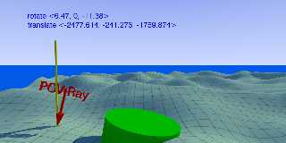
So, I manage to get the arrow on the rod by tweaking:

#local dir_y  = vaxis_rotate (lookat-cam_loc, vcross (cam_d, cam_up),
(0.483-screen_y_position*0.01)*cam_ang/image_width*image_height);
#local dir_xy = vaxis_rotate (dir_y, cam_up,
(0.535-screen_x_position*0.01)*cam_mirror*cam_ang);

replacing the 0.5 value by respectively 0.483 in dir_y and 0.535 in dir_xy.

Of course, this is entirely by just dumb trial and error, and I highly
doubt if it is significant. I wonder now if it holds for other scenes...
tests to do...

--
Thomas
Post a reply to this message
Attachments:
Download 'islaytest.png' (360 KB)
Preview of image 'islaytest.png'
|
|
| |
| |
|
|
|
|
| |
| |
|
|
Thomas de Groot <tho### [at] degrootorg> wrote:
> So, I manage to get the arrow on the rod by tweaking:
>
> #local dir_y  = vaxis_rotate (lookat-cam_loc, vcross (cam_d, cam_up),
> (0.483-screen_y_position*0.01)*cam_ang/image_width*image_height);
> #local dir_xy = vaxis_rotate (dir_y, cam_up,
> (0.535-screen_x_position*0.01)*cam_mirror*cam_ang);
>
> replacing the 0.5 value by respectively 0.483 in dir_y and 0.535 in dir_xy.
>
> Of course, this is entirely by just dumb trial and error, and I highly
> doubt if it is significant. I wonder now if it holds for other scenes...
> tests to do...
>

Yeah, I've found that tweaking *something* (one of several different things
actually) can put the arrow where it's supposed to be. But I suspect that your
values would need to change, when using a different camera angle? My own 'tweak
tests' have shown that the code as-is has the ideal overall values in its
arrow-placement equations-- but only at the most extreme telephoto/zoom camera
angle. As that angle value climbs toward 90 (more and more wide-angle), the
arrow position just gets progressively worse... and my own value-compensation
tweaks have to get larger, to correct it. Very frustrating so far.

BTW, what CamAng did you use for this test? 80?

On a brighter note:
I've discovered a simple fix for ALL of the traced 'normal' problems that I've
been dealing with!

To wit: After spending WAY too much time trying to come up with workarounds, I
replaced Norbert's
rotate <rx,0,rz>
with
Point_At_Trans(Norm) // a macro
from "functions.inc"

That's it!

Well, not quite: Even though the ARROW'S 'normal' orientation now looks great
all the time, the found rotation (in the #debugged output and on-screen) is no
longer correct-- because rotate <rx,0,rz> no longer agrees with whatever
Point_At_Trans is doing behind-the-scenes.

I haven't yet found a way to get at Point_At_Tran's hidden inner values, to USE
for the rotation.  Looking at its code (and at the other macros that it requires
in order to work), there's... a MATRIX.  :-(  I refuse to be beaten, though! Out
of desperation, I'm now *trying* to work out a way to turn a normal directly
into a set of rotations-- at least in two axes--that I can use to bypass
Point_At_Trans AND rotate <rx,0,rz> altogether.
Post a reply to this message
|
|
| |
| |
|
|
|
|
| |
| |
|
|
I think if you look at:

http://www.povray.org/documentation/view/3.7.1/246/

you'll see several things.

1. The +/- 0.5 range for x and y

2. camera angle is determined by changing the length of the direction vector.

3. I think this relates to the error you see, and it's decrease with smaller
camera angles.

Here's my crappy reasoning-by-analogy in the absence of the code in front of me,
and on short notice:

When you swivel a line through pivot point, a small change at the end results in
a large change in the other end when the pivot point is close ( small direction
vector / wide angle)

When you pull the camera way back, you have to make very large changes in the
position to have the same effect - or put the other way - any changes at the
other end are very small (your errors) for the same amount of change.

Think about that in terms of any trace() results and calculations based on those
- they're like angles, and like levers they can magnify (by integers or
fractions) the results.


I don't think you're/we're going to get very far fiddling with code or working
backwards from the existing macro.

Write some code to model a default camera scene, and then play with point
locations and their projection onto the z=1 plane.

Then you can work from there.

What you do (and understand) in a forward, stepwise manner, you can follow
stepwise, backwards to see what calculations you need to to go from screen
coordinates to 3D vector coordinates.
Post a reply to this message
|
|
| |
| |
|
|
|
|
| |
| |
|
|
_See_ what I mean here:

http://news.povray.org/povray.binaries.images/message/%3Cweb.587ce70b1652a4dcc437ac910%40news.povray.org%3E/#%3Cweb.587
ce70b1652a4dcc437ac910%40news.povray.org%3E
Post a reply to this message
|
|
| |
| |
|
|
|
|
| |
| |
|
|
OK, so here's a rudimentary object position / surface normal finding scene I
wrote from scratch, which shows the back-and-forth conversion of screen position
coordinates and 3D scene object coordinates.

Wrote 2 "shotgun" macros to pepper the target object with trace() calls to see
about the "underside" issue.

Play around with it, let me know questions, comments, improvements as always.


########################################################################

#version version;

#global_settings {assumed_gamma 1.0}

#include "colors.inc"

light_source {
 <0.5, 0.5, -1>
 color White
 fade_distance 20
 fade_power 2
}


#declare Default_location = <0, 0, 0>;  // 2.3.1.1.1 Location and Look_At
#declare Default_direction = <0, 0, 1>;  // 2.3.1.1.4 The Direction Vector
#declare Default_right = <1.33, 0, 0>;  // 2.3.1.1.6 Aspect Ratio
#declare Default_up = <0, 1, 0>;   // 2.3.1.1.6 Aspect Ratio
#declare Default_sky = <0, 1, 0>;   // 2.3.1.1.2 The Sky Vector

// When you specify the angle, POV-Ray adjusts the length of the direction
vector accordingly.
// The formula used is direction_length = 0.5 * right_length / tan(angle / 2)
// where right_length is the length of the right vector.
// You should therefore specify the direction and right vectors before the angle
keyword.
#declare Default_angle = 0;
// direction_length = 0.5 * right_length / tan(angle / 2)

// The look_at modifier should almost always be the last item in the camera
statement.
// If other camera items are placed after the look_at vector then the camera may
not continue to look at the specified point.
#declare Default_look_at = <0, 0, 1>;  // 2.3.1.1.1 Location and Look_At

#declare Aspect = image_width/image_height;
#declare A = <Aspect, 1, 1>;

camera {
 location Default_location
 direction Default_direction
 //right Default_right
 right x*image_width/image_height
 up  Default_up
 look_at Default_look_at
}


#declare TopRight = <0.5, 0.5, 1>;
#declare Far = 12;  // the far plane of a defined view frustum
// The diagonal distance from the Image Plane to a Far view frustum corner is
greater than the straight distance
//
#declare DiagonalLength = vlength (<(Far/2)*Aspect, (Far/2), Far> - TopRight);

// Frame the canvas
#declare Corner = array [4] {<-0.5, 0.5, 1>, <0.5, 0.5, 1>, <0.5, -0.5, 1>,
<-0.5, -0.5, 1>}
#declare Frustum = union {
#for (N, 0, 3)
 sphere {Corner [N] * A 0.01 pigment {Gray10}}
 sphere {Corner [N] * A * DiagonalLength 0.01 * DiagonalLength * 1.1 pigment
{Green}}
 // Here you can see that I just multply the sphere center's vector by a scalar:
the DiagonalLength
 // To give the rear sphere the same _apparent_ size (MOA), the radius is
multiplied by the distance
 // (Twice as far away needs to be twice as big to appear the same size)
 // Since you wouldn't be able to see one sphere behind the other, the radius is
increased by a factor of 1.1
#end
}

object {Frustum}


#macro Get3DPosition (Xpos, Ypos, Target, Mark)

 #declare Xpos = (Xpos - 0.5) * Aspect;
 #declare Ypos = -1*(Ypos - 0.5);
 #declare NormalVector = <0, 0, 0>;
 #declare From = <0, 0, 0>;
 #declare TraceThrough = <Xpos, Ypos, 1> - From;

 #declare PositionIn3D = trace (Target, From, TraceThrough, NormalVector);

 #if (vlength (NormalVector) != 0)
  cylinder {PositionIn3D, PositionIn3D+NormalVector, 0.01 pigment {Green}}
 #end

 // Indicate trace point
 #if (Mark)
  sphere {<Xpos, Ypos, 1> 0.005 pigment {Green}}
 #end // end if Mark
#end // end macro

#macro Convert2ScreenPos (Pos3D)
 #declare ScreenPosX = (Pos3D.x / Pos3D.z)/Aspect+0.5;
 #declare ScreenPosY = -1*((Pos3D.y / Pos3D.z)-0.5);
 #declare ScreenPos = <ScreenPosX, ScreenPosY>;
 ScreenPos
#end


// define an object
#declare Radius = 0.25;
#declare Object = sphere {<3, 5, 12> Radius pigment {Red}}

object {Object}

Get3DPosition (0.696, 0.094, Object, yes)


// Find the center of the object
#declare Min = min_extent (Object);
#declare Max = max_extent (Object);
#declare Center = Min + (Max-Min)/2;

#macro CircularShotgun (Target)
 #for (Angle, 0, 2*pi, 2*pi/12)
  #for (Rad, 0.9, 0.1, -0.1)
   #declare Offset = Angle + (2*pi/12 * Rad);
   #declare SP = Convert2ScreenPos (Center+<Rad*Radius*cos(Offset),
Rad*Radius*sin(Offset), 0>);
   #declare SPX = SP.x;
   #declare SPY = SP.y;

   Get3DPosition (SPX, SPY, Target, yes)
  #end
 #end
#end // end macro CircularShotgun

#macro BBShotgun (Target)
 #declare MinT = min_extent (Target);
 #declare MaxT = max_extent (Target);
 #declare Xrange = (MaxT.x - MinT.x);
 #declare Yrange = (MaxT.y - MinT.y);
 #debug concat(str (MinT.x, 0, 5), "\n")
 #debug concat(str (MaxT.x, 0, 5), "\n")
 #debug concat(str (Xrange, 0, 5), "\n")

 #for (Xvals, MinT.x, MaxT.x, Xrange/10)
  #for (Yvals, MinT.y, MaxT.y, Yrange/10)
   #debug concat(str (Xvals, 0, 5), "\n")
   #declare SP = Convert2ScreenPos (<Xvals, Yvals, Center.z>);
   #declare SPX = SP.x;
   #declare SPY = SP.y;

   Get3DPosition (SPX, SPY, Target, no)
  #end
 #end
#end // end macro BBShotgun

//CircularShotgun (Object)

BBShotgun (Object)

// end file
Post a reply to this message
|
|
| |
| |
|
|
|
|
| |
| |
|
|
"Bald Eagle" <cre### [at] netscapenet> wrote:
> I think if you look at:
>
> http://www.povray.org/documentation/view/3.7.1/246/
>
> you'll see several things...

Oh my GOD, that drawing is all WRONG!! If the 'position' is inside my eyeball,
and my eyeball shoots a ray toward my computer screen, it's at an ANGLE, and
then when the ray enters the screen and goes inside my computer, it's still at
an ANGLE, and, oh my GOD, nothing works right, and, and...

:-P

My feeble attempt at humor for today. "You know you've been raytracing too long
when..."
>
>
> I don't think you're/we're going to get very far fiddling with code or working
> backwards from the existing macro.

Funny factoid: As I continue working with the code and making little incremental
advances (while removing bits and pieces that are no longer needed), I see that
I'm already inching closer and closer to re-making the code from scratch. But
currently in a *slow* hit-and-miss fashion  :-/  I shall ponder on your sage
advice and conceptual suggestions ;-)

Another tidbit: Up until now, I've spent the VAST majority of time trying to
work out that stubborn 'normal' business from trace(...)-- but the real point of
the code is finding a POSITION (the returned translation.) The normal-based
rotations are more like pretty window-dressing-- albeit very nice window
dressing. I need to concentrate on the POSITIONING accuracy for awhile.
Post a reply to this message
|
|
| |
| |
|
|
|
|
| |
| |
|
|
On 3-10-2018 15:17, Kenneth wrote:
> Thomas de Groot <tho### [at] degrootorg> wrote:
>> So, I manage to get the arrow on the rod by tweaking:
>>
>> #local dir_y  = vaxis_rotate (lookat-cam_loc, vcross (cam_d, cam_up),
>> (0.483-screen_y_position*0.01)*cam_ang/image_width*image_height);
>> #local dir_xy = vaxis_rotate (dir_y, cam_up,
>> (0.535-screen_x_position*0.01)*cam_mirror*cam_ang);
>>
>> replacing the 0.5 value by respectively 0.483 in dir_y and 0.535 in dir_xy.
>>
>> Of course, this is entirely by just dumb trial and error, and I highly
>> doubt if it is significant. I wonder now if it holds for other scenes...
>> tests to do...
>>
>
> Yeah, I've found that tweaking *something* (one of several different things
> actually) can put the arrow where it's supposed to be. But I suspect that your
> values would need to change, when using a different camera angle? My own 'tweak
> tests' have shown that the code as-is has the ideal overall values in its
> arrow-placement equations-- but only at the most extreme telephoto/zoom camera
> angle. As that angle value climbs toward 90 (more and more wide-angle), the
> arrow position just gets progressively worse... and my own value-compensation
> tweaks have to get larger, to correct it. Very frustrating so far.
>
> BTW, what CamAng did you use for this test? 80?

Yes, 80. You know, I was just beating the bush and whistling a merry
tune, waiting for anything (a miracle?) to happen ;-) Totally crap of
course.

>
> On a brighter note:
> I've discovered a simple fix for ALL of the traced 'normal' problems that I've
> been dealing with!
>
> To wit: After spending WAY too much time trying to come up with workarounds, I
> replaced Norbert's
> rotate <rx,0,rz>
> with
> Point_At_Trans(Norm) // a macro
> from "functions.inc"
>
> That's it!

Indeed. I forgot about that one. See below for further thoughts.

>
> Well, not quite: Even though the ARROW'S 'normal' orientation now looks great
> all the time, the found rotation (in the #debugged output and on-screen) is no
> longer correct-- because rotate <rx,0,rz> no longer agrees with whatever
> Point_At_Trans is doing behind-the-scenes.

One may wonder what we really need. I personally believe we do not need
the rotation values resulting from the rx and rz calculations at all. We
use this macro (1) primarily to get an accurate 3D position on a given
surface; (2) possibly, we also need an orientation to the surface, thus
we need the normal. With Point_At_Trans(Norm) we can then orient our
object accurately on the surface.

>
> I haven't yet found a way to get at Point_At_Tran's hidden inner values, to USE
> for the rotation.  Looking at its code (and at the other macros that it requires
> in order to work), there's... a MATRIX.  :-(  I refuse to be beaten, though! Out
> of desperation, I'm now *trying* to work out a way to turn a normal directly
> into a set of rotations-- at least in two axes--that I can use to bypass
> Point_At_Trans AND rotate <rx,0,rz> altogether.

I think: forget about this. No need for this.

--
Thomas
Post a reply to this message
|
|
| |
| |
|
|
|
|
| |
| |
|
|
On 3-10-2018 16:12, Bald Eagle wrote:
> I think if you look at:
>
> http://www.povray.org/documentation/view/3.7.1/246/
>
> you'll see several things.
>
> 1. The +/- 0.5 range for x and y

Yes, of course. I new it was fundamental (but always push at the
fundamentals ;-) ). Had to be reminded.

>
> 2. camera angle is determined by changing the length of the direction vector.

Indeed. It is the way in which Gilles Tran's visibility test macro is
made operational in a given scene.

>
> 3. I think this relates to the error you see, and it's decrease with smaller
> camera angles.

probably yes.

>
> Here's my crappy reasoning-by-analogy in the absence of the code in front of me,
> and on short notice:
>
> When you swivel a line through pivot point, a small change at the end results in
> a large change in the other end when the pivot point is close ( small direction
> vector / wide angle)
>
> When you pull the camera way back, you have to make very large changes in the
> position to have the same effect - or put the other way - any changes at the
> other end are very small (your errors) for the same amount of change.
>
> Think about that in terms of any trace() results and calculations based on those
> - they're like angles, and like levers they can magnify (by integers or
> fractions) the results.

That seems reasonable indeed. I agree.

>
>
>
> I don't think you're/we're going to get very far fiddling with code or working
> backwards from the existing macro.
>
> Write some code to model a default camera scene, and then play with point
> locations and their projection onto the z=1 plane.
>
> Then you can work from there.
>
> What you do (and understand) in a forward, stepwise manner, you can follow
> stepwise, backwards to see what calculations you need to to go from screen
> coordinates to 3D vector coordinates.
>
>
>
>
>


--
Thomas
Post a reply to this message
|
|
| |
| |
|
|
|
|
| |
| |
|
|
On 4-10-2018 9:18, Thomas de Groot wrote:
> On 3-10-2018 15:17, Kenneth wrote:
>> Thomas de Groot <tho### [at] degrootorg> wrote:
>>> So, I manage to get the arrow on the rod by tweaking:
>>>
>>> #local dir_y  = vaxis_rotate (lookat-cam_loc, vcross (cam_d, cam_up),
>>> (0.483-screen_y_position*0.01)*cam_ang/image_width*image_height);
>>> #local dir_xy = vaxis_rotate (dir_y, cam_up,
>>> (0.535-screen_x_position*0.01)*cam_mirror*cam_ang);
>>>
>>> replacing the 0.5 value by respectively 0.483 in dir_y and 0.535 in
>>> dir_xy.
>>>
>>> Of course, this is entirely by just dumb trial and error, and I highly
>>> doubt if it is significant. I wonder now if it holds for other scenes...
>>> tests to do...
>>>
>>
>> Yeah, I've found that tweaking *something* (one of several different
>> things
>> actually) can put the arrow where it's supposed to be. But I suspect
>> that your
>> values would need to change, when using a different camera angle? My
>> own 'tweak
>> tests' have shown that the code as-is has the ideal overall values in its
>> arrow-placement equations-- but only at the most extreme
>> telephoto/zoom camera
>> angle. As that angle value climbs toward 90 (more and more
>> wide-angle), the
>> arrow position just gets progressively worse... and my own
>> value-compensation
>> tweaks have to get larger, to correct it. Very frustrating so far.
>>
>> BTW, what CamAng did you use for this test? 80?
>
> Yes, 80. You know, I was just beating the bush and whistling a merry
> tune, waiting for anything (a miracle?) to happen ;-) Totally crap of
> course.
>
>>
>> On a brighter note:
>> I've discovered a simple fix for ALL of the traced 'normal' problems
>> that I've
>> been dealing with!
>>
>> To wit: After spending WAY too much time trying to come up with
>> workarounds, I
>> replaced Norbert's
>> rotate <rx,0,rz>
>> with
>> Point_At_Trans(Norm) // a macro
>> from "functions.inc"
>>
>> That's it!
>
> Indeed. I forgot about that one. See below for further thoughts.
>

After testing, I think you will get more reliable results using
Reorient_Trans(y,Norm) instead. Otherwise the arrow text has a tendency
to rotate around the original y axis.

Btw, not in functions.inc but in transforms.inc ;-)


--
Thomas
Post a reply to this message
|
|
| |
| |
|
|
|
|
| |
| |
|
|
Thomas de Groot <tho### [at] degrootorg> wrote:

>
> After testing, I think you will get more reliable results using
> Reorient_Trans(y,Norm) instead. Otherwise the arrow text has a tendency
> to rotate around the original y axis.

You're right!

Reorient_Trans(y,Norm)

MUCH better. I had never noticed the difference before. (Point_At_Trans had
always been my 'go-to' macro for this kind of thing; I assumed that they both
operated the same way.) Thanks!
>
> Btw, not in functions.inc but in transforms.inc ;-)

OOPS.  Correct again.
Post a reply to this message
|
|
| |
| |
|
|
|
|
| |
| |
|
|
Thomas de Groot <tho### [at] degrootorg> wrote:

>
> After testing, I think you will get more reliable results using
> Reorient_Trans(y,Norm) instead. Otherwise the arrow text has a tendency
> to rotate around the original y axis.
>

[off-topic]
That little suggestion of yours has actually cleared up a long-standing mystery
for me. Having assumed that Point_At_Trans and Reorient_Trans produced the same
results, I had always used the former, for normals found on the surface of a
sphere (it just seemed easier)-- with the result being that my placed object
there rotated 90-degrees every now and then, relative to the surface's own
normal-- specifically, when the traced point crossed the border of
triangular-shaped 'quadrants' on the sphere surface. (It also occurs on the dips
and undulations of a height_field.)

I thought that this was due to a natural ambiguity of the found normal. But
Reorient_Trans doesn't perform that un-wanted rotation, as I see now. Excellent!
Post a reply to this message
|
|
| |
| |
|
|
|
|
| |
| |
|
|
On 4-10-2018 19:00, Kenneth wrote:
> Thomas de Groot <tho### [at] degrootorg> wrote:
>
>>
>> After testing, I think you will get more reliable results using
>> Reorient_Trans(y,Norm) instead. Otherwise the arrow text has a tendency
>> to rotate around the original y axis.
>>
>
> [off-topic]
> That little suggestion of yours has actually cleared up a long-standing mystery
> for me. Having assumed that Point_At_Trans and Reorient_Trans produced the same
> results, I had always used the former, for normals found on the surface of a
> sphere (it just seemed easier)-- with the result being that my placed object
> there rotated 90-degrees every now and then, relative to the surface's own
> normal-- specifically, when the traced point crossed the border of
> triangular-shaped 'quadrants' on the sphere surface. (It also occurs on the dips
> and undulations of a height_field.)
>
> I thought that this was due to a natural ambiguity of the found normal. But
> Reorient_Trans doesn't perform that un-wanted rotation, as I see now. Excellent!
>
>

Thanks for this little insight into working processes. From my side, I
have always used Reorient_Trans instead of Point_At_Trans, probably for
the reasons you mention, through the advice of somebody else, like
usually happily happens in these ng's. The descriptions in the docs are
the shortest possible, but it tells nonetheless the difference in
concept from which one can understand the behaviour, with a bit of luck.
;-)

Maybe this is a little bit clearer:
http://www.f-lohmueller.de/pov_tut/trans/trans_470e.htm

--
Thomas
Post a reply to this message
|
|
| |
| |
|
|
|
|
| |
|
|