|
|
|
|
|
|
| |
| |
|
|
|
|
| |
| |
|
|
So, I am using this macro to generate chromadepth textures:


// this script assumes the depth effect is *linear* from near to far,
// which may not be the case
// red, white, blue
#macro MakeChromadepthTextureCameraRWB(CameraLocation, CameraLookAt)
	#local iMax = 240;
	pigment
	{
		spherical
		color_map
		{
			[0.0 color srgb <0,0,1>]
			[0.5 color srgb <1,1,1>]
			[1.0 color srgb <1,0,0>]
		}
	}
//	finish
//	{
//		ambient 1
//		diffuse 0
//	}
	scale vlength(CameraLocation - CameraLookAt) * 2
	translate CameraLocation
#end

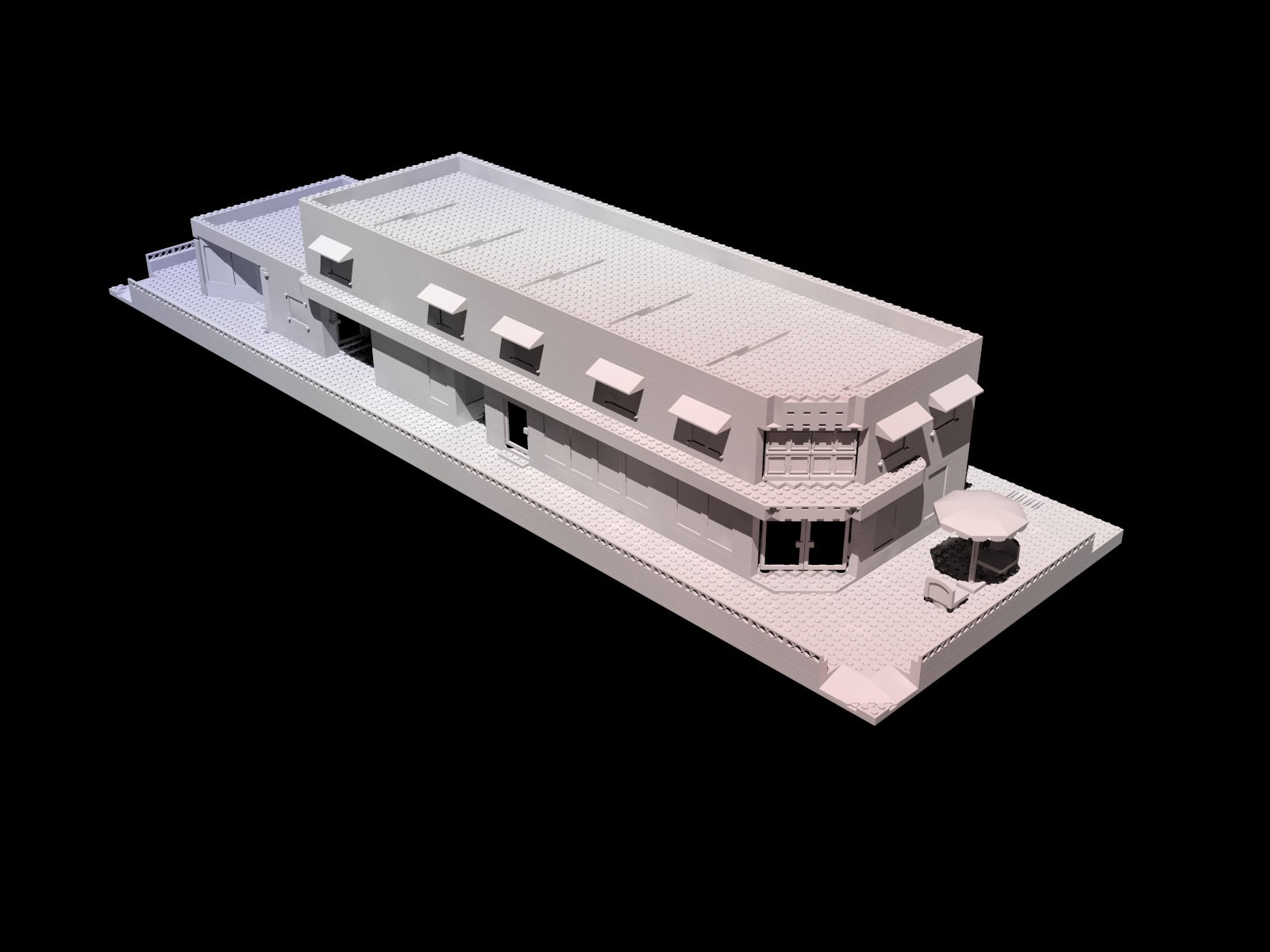
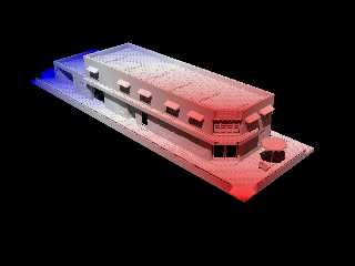
The texture is centered on the camera location, and stretches to a point
opposite the model. The problem is that the model ends up mostly white,
with only touches of blue and red, as you can see in the attached image.

I think the texture should hug the model a bit closer, so that more red
and blue are visible. The problem is that the texture is centered on the
camera instead of the model, or I could just scale the texture a bit
smaller.

What method can I use to fix the texture? I know what the model's center
point and bounding box are.

Thanks.


Mike
Post a reply to this message
Attachments:
Download 'wrapper_showcase.jpg' (225 KB)
Preview of image 'wrapper_showcase.jpg'
|
|
| |
| |
|
|
|
|
| |
| |
|
|
On 17/02/2018 12:29, Mike Horvath wrote:
> or I could just scale the texture a bit smaller.

I would experiment with that to start with. The results might give you
an idea.
It could be that you just need to "calibrate".

--

Regards
     Stephen
Post a reply to this message
|
|
| |
| |
|
|
|
|
| |
| |
|
|
Mike Horvath <mik### [at] gmail com> wrote:
>
> scale vlength(CameraLocation - CameraLookAt) * 2
> translate CameraLocation
Just from sketching some graphical ideas on paper, I think there are probably
two problems involved-- although I hope that I'm understanding the intended use
of your macro!
The spherical pattern by default occupies a sphere space of radius 1.0. The
macro is finding the distance from the *center* of that sphere to the center of
your model (I'm guessing that's what you have in mind, anyway.) Then the camera
is translated to the center point of the scaled-up pattern. So far, the idea
sounds OK. But the spherical pattern's outer 'surface' is already 1 unit away
from the camera location to start with-- so I'm wondering how far that 'new'
outer surface extends to. And it looks like the X2 multiplier is making it much
larger than it needs to be.(?)
If that's the case, then the color_map entries are also getting 'stretched out'.
Maybe they need pre-compressing, so to speak.
Instead of this...
[0.0 color srgb <0,0,1>]
[0.5 color srgb <1,1,1>]
[1.0 color srgb <1,0,0>]
.... maybe *something* like this...
[0.4 color srgb <0,0,1>]
[0.5 color srgb <1,1,1>]
[0.6 color srgb <1,0,0>]
Or maybe the vlength formula should be
scale vlength(CameraLocation - CameraLookAt - 1)
??? com> wrote:
>
> scale vlength(CameraLocation - CameraLookAt) * 2
> translate CameraLocation
Just from sketching some graphical ideas on paper, I think there are probably
two problems involved-- although I hope that I'm understanding the intended use
of your macro!
The spherical pattern by default occupies a sphere space of radius 1.0. The
macro is finding the distance from the *center* of that sphere to the center of
your model (I'm guessing that's what you have in mind, anyway.) Then the camera
is translated to the center point of the scaled-up pattern. So far, the idea
sounds OK. But the spherical pattern's outer 'surface' is already 1 unit away
from the camera location to start with-- so I'm wondering how far that 'new'
outer surface extends to. And it looks like the X2 multiplier is making it much
larger than it needs to be.(?)
If that's the case, then the color_map entries are also getting 'stretched out'.
Maybe they need pre-compressing, so to speak.
Instead of this...
[0.0 color srgb <0,0,1>]
[0.5 color srgb <1,1,1>]
[1.0 color srgb <1,0,0>]
.... maybe *something* like this...
[0.4 color srgb <0,0,1>]
[0.5 color srgb <1,1,1>]
[0.6 color srgb <1,0,0>]
Or maybe the vlength formula should be
scale vlength(CameraLocation - CameraLookAt - 1)
???
Post a reply to this message
|
|
| |
| |
|
|
|
|
| |
| |
|
|
Mike Horvath <mik### [at] gmailcom> wrote:

> The texture is centered on the camera location, and stretches to a point
> opposite the model. The problem is that the model ends up mostly white,
> with only touches of blue and red, as you can see in the attached image.

I think what you want to do is center the texture on the model, and scale it
according to the bounding box.   That way you get the full range of colors on
the model.

If you're actually trying to somehow encode the distance from the camera into
the texture, then clipka posted a way to do that recently in response to
someone's query.

In any event, include a plane in the scene, and texture that with your color-map
so you can see the whole pattern and how it behaves in relation to where your
object is.
Post a reply to this message
|
|
| |
| |
|
|
|
|
| |
| |
|
|
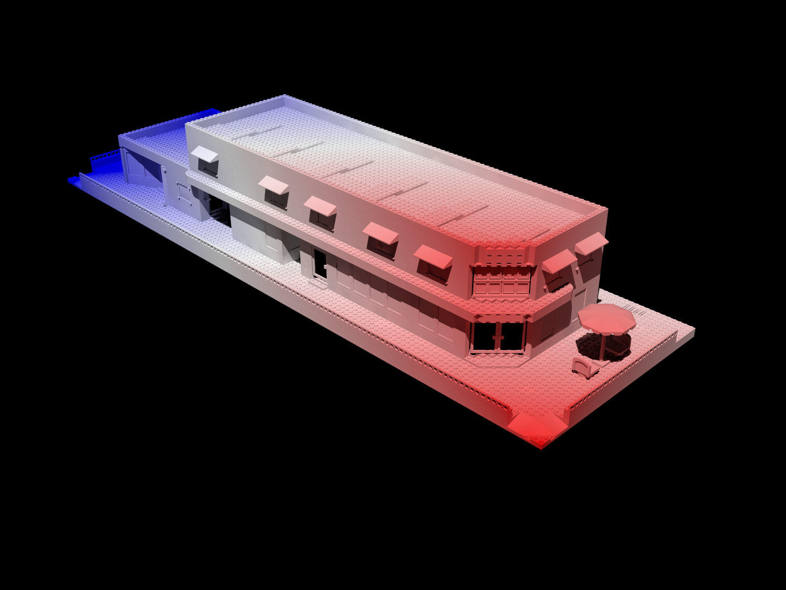
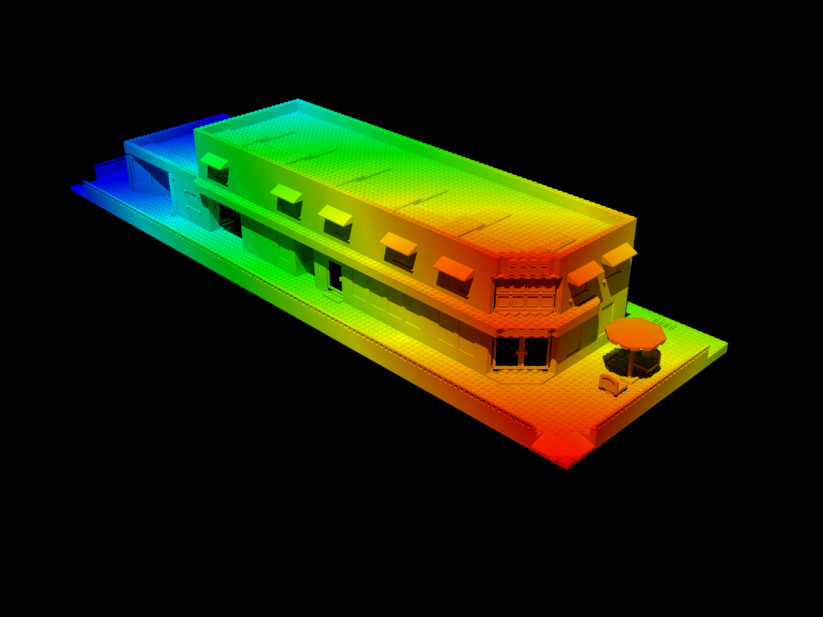
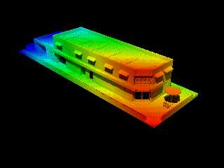
I ended up using this:


// This script assumes the depth effect is *linear* from near to far,
which may not be the case.
// red, white, blue
#macro MakeChromadepthTextureCameraRWB(CameraLocation, CameraLookAt,
FudgePercent)
	#local FudgeMin = FudgePercent/100/2;
	#local FudgeMax = 1 - FudgePercent/100/2;
	pigment
	{
		spherical
		color_map
		{
			[0.0		color srgb <0,0,1>]
			[FudgeMin	color srgb <0,0,1>]
			[0.5		color srgb <1,1,1>]
			[FudgeMax	color srgb <1,0,0>]
			[1.0		color srgb <1,0,0>]
		}
	}
//	finish
//	{
//		ambient 1
//		diffuse 0
//	}
	scale vlength(CameraLocation - CameraLookAt) * 2
	translate CameraLocation
#end


I can shrink and grow the texture using the FudgePercent parameter. I
think this is as close as I'll get.


Mike
Post a reply to this message
|
|
| |
| |
|
|
|
|
| |
| |
|
|
Forgot to post the images.


Mike
Post a reply to this message
Attachments:
Download 'wrapper_showcase_chromadepth_01.png' (582 KB)
Download 'wrapper_showcase_chromadepth_02.png' (511 KB)
Preview of image 'wrapper_showcase_chromadepth_01.png'
Preview of image 'wrapper_showcase_chromadepth_02.png'
|
|
| |
| |
|
|
|
|
| |
| |
|
|
Mike Horvath <mik### [at] gmailcom> wrote:
> I ended up using this:
>
>
> // This script assumes the depth effect is *linear* from near to far,
> which may not be the case.
>

The idea looks interesting! And your model proves that it works.

In the interim time, I had a brainstorm. I had to work it out graphically on
paper, discarding one idea after another, but finally came up with a solution.
It's more complex than your's, but it doesn't have any fudge factor that I know
of. I have to describe it in words; if you can put it into an equation, kudos
;-) (I'm really tired and the ol' brain is fizzling out...)

1) Choose a camera position; it can be anywhere. (So can the object.)

2) Get the bounding-box coordinates of the object-- the farthest and nearest
corner locations, whatever they happen to be.

3) find vlength from camera to nearest bounding-box corner. Call it L-1

4) find vlength from camera to farthest B-B corner. Call it L-2

5) L-1 / L-2 = S   This will be somewhere between 0.0 and 1.0-- it depends on
how far your object is from the camera. The farher apart, the larger this will
be.

6)  Then, (1.0 - S) = T

7) Using T, change your spherical color_map's original 0.0-to-1.0 index values
to a more 'squased' version, closer to the outer spherical 'surface'. (And don't
scale it up yet.)

     [0.0 BLUE] // outer radius of spherical pattern
     [.5*T WHITE]
     [T  RED ]  // what used to be the center point of the pattern; now father
                // out toward edge

8) Now scale-up the spherical pattern by L-2. That *should* put the outer
edge of the BLUE at or near the object's farthest bounding-box corner; and RED
should begin at or neat the closer corner.

CAVEAT: No guarantees are implied... :-P
Post a reply to this message
|
|
| |
| |
|
|
|
|
| |
| |
|
|
"Kenneth" <kdw### [at] gmailcom> wrote:
> Mike Horvath <mik### [at] gmailcom> wrote:
> > I ended up using this:
> >
> >
> > // This script assumes the depth effect is *linear* from near to far,
> > which may not be the case.
> >
>
> The idea looks interesting! And your model proves that it works.
>
> In the interim time, I had a brainstorm. I had to work it out graphically on
> paper, discarding one idea after another, but finally came up with a solution.
> It's more complex than your's, but it doesn't have any fudge factor that I know
> of. I have to describe it in words; if you can put it into an equation, kudos
> ;-) (I'm really tired and the ol' brain is fizzling out...)
>
> 1) Choose a camera position; it can be anywhere. (So can the object.)
>
> 2) Get the bounding-box coordinates of the object-- the farthest and nearest
> corner locations, whatever they happen to be.
>
> 3) find vlength from camera to nearest bounding-box corner. Call it L-1
>
> 4) find vlength from camera to farthest B-B corner. Call it L-2
>
> 5) L-1 / L-2 = S   This will be somewhere between 0.0 and 1.0-- it depends on
> how far your object is from the camera. The farher apart, the larger this will
> be.
>
> 6)  Then, (1.0 - S) = T
>
> 7) Using T, change your spherical color_map's original 0.0-to-1.0 index values
> to a more 'squased' version, closer to the outer spherical 'surface'. (And don't
> scale it up yet.)
>
>      [0.0 BLUE] // outer radius of spherical pattern
>      [.5*T WHITE]
>      [T  RED ]  // what used to be the center point of the pattern; now father
>                 // out toward edge
>
> 8) Now scale-up the spherical pattern by L-2. That *should* put the outer
> edge of the BLUE at or near the object's farthest bounding-box corner; and RED
> should begin at or neat the closer corner.
>
> CAVEAT: No guarantees are implied... :-P


Maybe this is asking a lot, but I believe such features should be hardcoded into
POV, with a pass system where pov could render a z pass, motion vector pass,
ambient occlusion (proximity pattern) etc. so they would be rendered in the same
process as main image, stored in its secondary layers when using EXR format, and
be usable for compositing.
Post a reply to this message
|
|
| |
| |
|
|
|
|
| |
| |
|
|
So, I finally coded-up my idea, and it does indeed put the 'center' color of the
color_map across the center of the object. That part works, at least. But the
color pattern's 'limits' on the object have a problem: the color spread doesn't
extend all the way across. So far, after several days of trying to figure out
why, I still don't have a clue. I tried changing *every* parameter in the code,
but no luck-- although there's probably a hidden 'clue' in those trials.

So, I had to resort to some fudge-factors as well :-/  I eventually found one
set of those that actually works consistently... so the overall scheme is
workable after all. Only two 'fudging' values need changing, by eye; they depend
on relative distance between object and camera, and on the scale of the object.
I don't know if those values change linearly, exponentially, or what.
Essentially, they increase the distance between the object's found  bounding-box
coordinates, *as if* the object is larger. A clue?

The first image is the result of the initial code idea; the second is with the
fix. The fudge factors indicate that the 'squashed' color_map values depend on
some kind of so-far-unknown variable. There HAS to be an answer; I just haven't
found it yet :-(

The camera and object positions are arbitrary, as is object scale, and can be
anything... within reason ; there can be precision issues behind-the-scenes. See
the #debug messages.

//------------------------
#declare CAM_LOCATION = <32, 56, -35>*3; // easily change location using the
// (positive) multiplier (actually changes it between location <0,0,0> and
// farther out)
#declare OBJECT_CENTER_LOCATION = <3,6,22>*1.0; // ditto
#declare OBJECT_SCALE =  2.7;
#declare CAM_ANGLE = 3; // 0.9 Just to easily change the camera angle when
// you change object scale or camera/object distance.

// main camera
camera {
  perspective
  location  CAM_LOCATION
  look_at   OBJECT_CENTER_LOCATION
  right     x*image_width/image_height  // aspect
  angle CAM_ANGLE
}

/*
// OR, separate camera, 'un-coupled' from code, looking from another location
// way above
camera {
  perspective
  location  <0,500,0>
  look_at   OBJECT_CENTER_LOCATION
  right     x*image_width/image_height  // aspect
  angle CAM_ANGLE
}
*/

light_source {
  0*x
  color rgb .7
  translate <40, 80, 30>
}

background{rgb .1}

// stripes are 1-unit apart
plane{y,0
    pigment{
           average
           pigment_map{
                [ 1 gradient x
                 color_map{
                     [.05 rgb .8]
                     [.05 rgb .3]
                          }
                ]
                [ 1 gradient z
                 color_map{
                     [.05 rgb .8]
                     [.05 rgb .3]
                          }
                ]
                      }
           scale 1
           }
    }

#declare OBJECT_1 =  // does not need to be centered on origin when made
// box{0,<1,.1,1> scale OBJECT_SCALE
// rotate 40
// translate OBJECT_CENTER_LOCATION
// }
// OR...
cylinder{-.05*y,.05*y 1
   scale OBJECT_SCALE
   translate OBJECT_CENTER_LOCATION  // yes, PRE-translated -- it's part
                                     // of the idea
   }

#declare NEAR_CORNER = min_extent(OBJECT_1);
#declare FAR_CORNER = max_extent(OBJECT_1);

#declare L_1 = vlength(NEAR_CORNER - CAM_LOCATION) - 0;  // or - 1.68 FUDGE
// FACTOR
#declare L_2 = vlength(FAR_CORNER - CAM_LOCATION) + 0;  // or + 1.44 FUDGE
// FACTOR

#declare S = L_1/L_2;
#declare T = 1.0 - S;

#declare SPHERE_PIG =
pigment{
     spherical
     color_map{
          [0 rgb 3]
          [0 rgb <0,0,1>] // BLUE -- outside edge of pattern
          [0.5*T rgb <1,1,0>] // YELLOW
          [T rgb <1,0,0>] // RED
          [T rgb 3]
          }

       /*
      // to experiment with...
      color_map{
          [0 rgb 3]
          [0 rgb <0,0,1>] // BLUE -- outside edge of pattern
            [.48*T rgb <0,0,1>]
            [.48*T rgb <1,1,0>]
            [.52*T rgb <1,1,0>]
            [.52*T rgb <1,0,0>]
          [T rgb <1,0,0>]
          [T rgb 3]
          }
       */

      scale L_2
      translate CAM_LOCATION
      }

object{OBJECT_1// already translated
     pigment{SPHERE_PIG} // ditto
     }

#debug concat("\n", "object SCALE = ",str(OBJECT_SCALE,0,9),"\n")
#debug concat("\n", "distance to bounding box NEAR corner (L_1) =
",str(vlength(NEAR_CORNER - CAM_LOCATION) - 0,0,9),"\n")
#debug concat("\n", "distance to bounding box FAR corner (L_2) =
",str(vlength(FAR_CORNER - CAM_LOCATION) - 0,0,9),"\n")
#debug concat("\n", "L_1/L_2 = ",str(L_1/L_2,0,9),
"  (should never go over 1.0 !)","\n")
#debug concat("\n", "T = ",str(T,0,9),"\n")
Post a reply to this message
Attachments:
Download 'chromadepth_example.jpg' (225 KB)
Preview of image 'chromadepth_example.jpg'

|
|
| |
| |
|
|
|
|
| |
| |
|
|
On 2/19/2018 11:13 AM, Kenneth wrote:
> So, I finally coded-up my idea, and it does indeed put the 'center' color of the
> color_map across the center of the object. That part works, at least. But the
> color pattern's 'limits' on the object have a problem: the color spread doesn't
> extend all the way across. So far, after several days of trying to figure out
> why, I still don't have a clue. I tried changing *every* parameter in the code,
> but no luck-- although there's probably a hidden 'clue' in those trials.
>
> So, I had to resort to some fudge-factors as well :-/  I eventually found one
> set of those that actually works consistently... so the overall scheme is
> workable after all. Only two 'fudging' values need changing, by eye; they depend
> on relative distance between object and camera, and on the scale of the object.
> I don't know if those values change linearly, exponentially, or what.
> Essentially, they increase the distance between the object's found  bounding-box
> coordinates, *as if* the object is larger. A clue?
>
> The first image is the result of the initial code idea; the second is with the
> fix. The fudge factors indicate that the 'squashed' color_map values depend on
> some kind of so-far-unknown variable. There HAS to be an answer; I just haven't
> found it yet :-(
>
> The camera and object positions are arbitrary, as is object scale, and can be
> anything... within reason ; there can be precision issues behind-the-scenes. See
> the #debug messages.

Awesome! Let us know when you figure out why the fudge factor is needed.
If you flip over the disc you'll see that the second fudge factor is too
small. You need to set it to + 1.65 instead of + 1.44.


Mike
Post a reply to this message
|
|
| |
| |
|
|
|
|
| |
| |
|
|
Mike Horvath <mik### [at] gmailcom> wrote:

> Awesome! Let us know when you figure out why the fudge factor is needed.
> If you flip over the disc you'll see that the second fudge factor is too
> small. You need to set it to + 1.65 instead of + 1.44.
>
>
Thanks. Yeah, that doesn't surprise me at all! And in some of the tests I ran by
rotating the object, the L_1/L_2 equation-- the min_extent and max_extent --
actually exceeded 1.0. Meaning, the far bounding_box corner was being sensed as
closer to the camera than the near one(!) That made no sense, but it's
*probably* precision-errors, due to some of the values becoming really small
(when the camera/object distance is large.)

Currently, I can live with the fudge factors-- they're at least somewhat easy to
fiddle with, until I figure out what's happening-- but they make no sense. And
neither did any of the other fudgy things I tried. That kind of arbitrary stuff
really bugs me.

I'll hopefully awake one morning with an 'A-HA' epiphany, and it will all be
clear. But don't hold your breath :-P

I have a sneaking feeling that, with a *complex* object made of lots of parts,
its  bounding_box corner locations may throw off the 'centerline' location of
the color_map. Requiring more fudge factors, maybe... :-O
Post a reply to this message
|
|
| |
| |
|
|
|
|
| |
| |
|
|
Mike Horvath <mik### [at] gmailcom> wrote:

> // This script assumes the depth effect is *linear* from near to far,
> which may not be the case.

I've been thinking about that as well. My opinion is that it's NOT linear-- that
the RED/BLUE 'mix' should not be equal across the model (and/or that the
mid-point 'mix line' should not extend exactly to the mid-point of the model or
of a larger entire scene.) The analogy I thought of was the visual effect of
looking through binoculars at distant objects: The 3-D effect is reduced there;
objects at different distances look kind of like flat planes, because our eyes
are only _____ inches apart (not much parallax.) And MUCH more of a 3-D effect
looking at closer objects.
Post a reply to this message
|
|
| |
| |
|
|
|
|
| |
| |
|
|
On 2/19/2018 8:50 PM, Kenneth wrote:
> Mike Horvath <mik### [at] gmailcom> wrote:
>
>> // This script assumes the depth effect is *linear* from near to far,
>> which may not be the case.
>
> I've been thinking about that as well. My opinion is that it's NOT linear-- that
> the RED/BLUE 'mix' should not be equal across the model (and/or that the
> mid-point 'mix line' should not extend exactly to the mid-point of the model or
> of a larger entire scene.) The analogy I thought of was the visual effect of
> looking through binoculars at distant objects: The 3-D effect is reduced there;
> objects at different distances look kind of like flat planes, because our eyes
> are only _____ inches apart (not much parallax.) And MUCH more of a 3-D effect
> looking at closer objects.
>

Well, you can see this effect in POV-Ray too if you change the camera's
angle parameter.

https://commons.wikimedia.org/wiki/File:Camera_focal_length_distance_house_animation.gif


Mike
Post a reply to this message
|
|
| |
| |
|
|
|
|
| |
| |
|
|
On 19-2-2018 17:13, Kenneth wrote:
> So, I finally coded-up my idea, and it does indeed put the 'center' color of the
> color_map across the center of the object. That part works, at least. But the
> color pattern's 'limits' on the object have a problem: the color spread doesn't
> extend all the way across. So far, after several days of trying to figure out
> why, I still don't have a clue. I tried changing *every* parameter in the code,
> but no luck-- although there's probably a hidden 'clue' in those trials.
>
> So, I had to resort to some fudge-factors as well :-/

As far as I know from docs and/of previous discussions, min_extent and
max_extent do not give the /exact/ extent of the object. So, I am not
really surprised you need a fudge factor...

--
Thomas
Post a reply to this message
|
|
| |
| |
|
|
|
|
| |
| |
|
|
On 2/20/2018 2:43 AM, Thomas de Groot wrote:
> On 19-2-2018 17:13, Kenneth wrote:
>> So, I finally coded-up my idea, and it does indeed put the 'center'
>> color of the
>> color_map across the center of the object. That part works, at least.
>> But the
>> color pattern's 'limits' on the object have a problem: the color
>> spread doesn't
>> extend all the way across. So far, after several days of trying to
>> figure out
>> why, I still don't have a clue. I tried changing *every* parameter in
>> the code,
>> but no luck-- although there's probably a hidden 'clue' in those trials.
>>
>> So, I had to resort to some fudge-factors as well :-/
>
> As far as I know from docs and/of previous discussions, min_extent and
> max_extent do not give the /exact/ extent of the object. So, I am not
> really surprised you need a fudge factor...
>

LDraw models all have bounding boxes defined during the conversion
process. I will try and see if I still need any fudge factors after
plugging those values in instead of min_extent and max_extent.


Mike
Post a reply to this message
|
|
| |
| |
|
|
|
|
| |
| |
|
|
On 2/20/2018 4:50 AM, Mike Horvath wrote:
> On 2/20/2018 2:43 AM, Thomas de Groot wrote:
>> On 19-2-2018 17:13, Kenneth wrote:
>>> So, I finally coded-up my idea, and it does indeed put the 'center'
>>> color of the
>>> color_map across the center of the object. That part works, at least.
>>> But the
>>> color pattern's 'limits' on the object have a problem: the color
>>> spread doesn't
>>> extend all the way across. So far, after several days of trying to
>>> figure out
>>> why, I still don't have a clue. I tried changing *every* parameter in
>>> the code,
>>> but no luck-- although there's probably a hidden 'clue' in those trials.
>>>
>>> So, I had to resort to some fudge-factors as well :-/
>>
>> As far as I know from docs and/of previous discussions, min_extent and
>> max_extent do not give the /exact/ extent of the object. So, I am not
>> really surprised you need a fudge factor...
>>
>
> LDraw models all have bounding boxes defined during the conversion
> process. I will try and see if I still need any fudge factors after
> plugging those values in instead of min_extent and max_extent.
>
>
> Mike


I attached the macros I created based on your code. However, it still
requires some labor on the user's part, since the camera could be
located anywhere, and not necessarily closest to the minimum extent or
farthest from the maximum extent, etc. There needs to be some way to
automatically determine which of the bounding box's 8 corners is the
closest and which is the farthest from the camera.


Mike
Post a reply to this message
Attachments:
Download 'utf-8' (2 KB)
|
|
| |
| |
|
|
|
|
| |
| |
|
|
Thomas de Groot <tho### [at] degrootorg> wrote:

>
> As far as I know from docs and/of previous discussions, min_extent and
> max_extent do not give the /exact/ extent of the object. So, I am not
> really surprised you need a fudge factor...
>

I assumed that a really simple object like my cylinder wouuld have a
well-defined, close-fitting bounding box. The strange thing is, I still don't
fully understand why the color_map spread on the object is so narrow (when not
using the fudge factors). I keep thinkling that my code has a conceptual error
somewhere-- but if so, I haven't yet found it. In theory, it should be doing
what I want it to do.

My own first thoughts were about a possible bounding-box error as well. But that
seems kind of strange, the reason being that the color_map 'spread boundaries'
actually increases across more of the object-- a wider color_map appearance--the
closer the object is to the camera position. I would think that the spread would
remain constant,  *if* the bounding-box error was constant as well. Which keeps
leading me back to wondering if there's a conceptual error...  ;-/
Post a reply to this message
|
|
| |
| |
|
|
|
|
| |
| |
|
|
Mike Horvath <mik### [at] gmailcom> wrote:
>
> I attached the macros I created based on your code. However, it still
> requires some labor on the user's part, since the camera could be
> located anywhere, and not necessarily closest to the minimum extent or
> farthest from the maximum extent, etc. There needs to be some way to
> automatically determine which of the bounding box's 8 corners is the
> closest and which is the farthest from the camera.
>

Hmm, an interesting thought.

I've always assumed that finding vlength to the min_extent/max_extent
bounding-box positions would never fail to return the proper spatial
coordinates, regardless of what 'orientation' the object was in, relative to the
vlength 'shoot-from' position. In other words (AFAIU) the object itself has
'set' bounding box corner values for the particular spatial location that it's
at-- values relative to the origin at <0,0,0> (and which can naturally *change*
depending on the object's rotation, for example-- i.e., the corners shift
around.) And that there's always *some* set of distinct nearest-corner and
farthest-corner values, *as referenced to the vlength shoot-from position*, not
the origin. My assumption is that the vlength/min_extent/max_extent combination
would *always* pick out what IT sees as the nearest corner and farthest corner,
relative to itself (not relative to the <0,0,0> origin.)

If I'm wrong about any of this, then my code concept is wrong as well, in a
strangely subtle way.

I do recall past discussions in 'the old days' that there were some problems
with bounding boxes not being translated (rotated?) correctly when the object
itself was; but that was fixed, ASAIK.

The answer to all this may be buried in my #debug messages-- all the various
values returned-- but it looks like some vector analysis is required to tease
out an answer. Ugh.
Post a reply to this message
|
|
| |
| |
|
|
|
|
| |
| |
|
|
I don't have time at the moment to sift through your code or write any of my
own, but I'll make a few observations and [hopefully helpful] comments.

First, make sure your camera position and object-camera line of sight are
normalized to be along a primary axis.

Then the bounding box, pattern alignment, and distance calculations are easy to
calculate, code, and align properly.

Once you have done that, apply your pattern and then UNdo it - which will shift
the pattern along with the object.

Truly a place where "letting POV-Ray do the heavy lifting" for the vector math
and matrix transforms is strongly advisable.

finding the nearest part of the bounding box ought to be as simple as min (a, b,
c, d, e, f, g, h) where a-h are distances from the camera to the bb corners.
Post a reply to this message
|
|
| |
| |
|
|
|
|
| |
| |
|
|
"Bald Eagle" <cre### [at] netscapenet> wrote:

>
> finding the nearest part of the bounding box ought to be as simple as min (a, b,
> c, d, e, f, g, h) where a-h are distances from the camera to the bb corners.

Nice idea. I did it another way-- making a semi-transparent box object using the
min_extent/max_extent coordinates, with the box superimposed on my disc object.
I'm running some visual tests at the moment-- and those corner coordinates ARE
part of the problem, especially if the object happens to be pre-rotated. I'm
sifting through the results, and will report back.

What it looks like so far is that, if I (pre-)rotate the object before being
translated, the ''near' and 'far' bounding_box corners are actually rotating
along with the object-- i.e., their 'near' and 'far' relationship appears to be
reversing! (Or vlength is choosing the wrong corner?) My L_1/L_2 equation and
its #debug message bear this out. If that is expected behavior, it's a surprise
to me. Very mysterious.

Meanwhile, I did another test with my code to make sure the idea itself-- with
the various scalings and transformations-- is sound. (I made some visible sphere
objects that 'mimic' the location of camera and object, and the distance between
them.) It looks like the code itself is working exactly the way I intended.
Post a reply to this message
|
|
| |
| |
|
|
|
|
| |
| |
|
|
Mike Horvath <mik### [at] gmailcom> wrote:

>
> Well, you can see this effect in POV-Ray too if you change the camera's
> angle parameter.
>
>
https://commons.wikimedia.org/wiki/File:Camera_focal_length_distance_house_animation.gif
>

I hadn't seen that before. it's a nice illustration of what happens.

A couple of years ago, I made some related (or not!) tests with my digital
camera: Setting it on a tripod, I made a wide-angle photo of a scene, and then a
telephoto view. I wanted to see if there was any apparent '3-D depth change' to
objects when comparing the two, based on the lens setting (probably a silly
experiment with a foregone conclusion, but I wanted to test it anyway.) I took
the wide-angle photo into Photoshop and blew it up, and chose a small rectangle
of a distant object to compare to the telephoto view. Except for the noisy
nature
of the blow-up, they both looked identical.
Post a reply to this message
|
|
| |
| |
|
|
|
|
| |
| |
|
|
I'll see if I can provide some of my code from the camera view frustum project -
that had some good basic code that I looked up to implement.  It might be
applicable.

Also, I'd start by "going 2-D" and looking down from halfway between the camera
and object, with an orthographic camera, and a gridlined plane.
That might help highlight issues and provide more visual clues.
Post a reply to this message
|
|
| |
| |
|
|
|
|
| |
| |
|
|
"Kenneth" <kdw### [at] gmailcom> wrote:

>
> What it looks like so far is that, if I (pre-)rotate the object before being
> translated, the ''near' and 'far' bounding_box corners are actually rotating
> along with the object-- i.e., their 'near' and 'far' relationship appears to be
> reversing! (Or vlength is choosing the wrong corner?)

No, I was mistaken about that-- the corners aren't 'rotating' with the object.
But there *are* definite reversals of 'near' and 'far' corners, depending on
....? (camera/object distance, maybe.)  I'm still working that out...

Bald Eagle wrote:
> Also, I'd start by "going 2-D" and looking down from halfway between the camera
> and object, with an orthographic camera, and a gridlined plane.
> That might help highlight issues and provide more visual clues.

That's pretty much exactly what I'm doing right now, with a few bells and
whistles thrown in too. I resorted to animation tests, to try and *clearly*
determine what's up with the applied color_map re: the changing-shape(!)
bounding_box...
Post a reply to this message
|
|
| |
| |
|
|
|
|
| |
| |
|
|
Well, I figured out what the problem is. I've posted an image of my latest
tests. (The white arrow illustrates the camera-to-object direction-- and shows
that the code itself is working; the color 'stripes' on the object are in the
correct orientation of the 'spherical' pattern, slicing through the object.) In
the images, I put small spheres at the min_extent and max_extent positions. The
blue box represnts the bounding-box shape that's found.

But POV-ray's automatic bounding boxes don't behave the way I thought :-(

I was assuming that a bounding box would 'hug' the object. As you can see in the
top images, it does. Nice and tight. But when an object is rotated, the bounding
box changes its size-- whereas I was expecting it to remain just like the top
images no matter what... like the object was 'wrapped' in the same-size box,
which would rotate with it. That was a major misconception on my part, and it
definitely affects my code idea. I have no idea how to compensate for that-- no
'fudge factor' that I can think of.

At first, I thought this was really screwy behavior; but I see now what is
actually happening. The bounding box shape is like an 'orthographic projection'
of the object boundaries-- AS IF PROJECTED FROM strictly the x/y/z planes.
That's the key. The camera or object location doesn't affect that
strictly-rectangular shape. (If I were to set up a camera looking exactly in x,
y, or z, I'm sure I would see only one face of the box.)

I now seem to remember newsgroup discussions in the past about this behavior,
but I had forgotten about it.

The images also show a sphere superimposed onto the cylinder object. Its radius
is 1/2 of the diagonal distance between min_extent and max_extent, and I
textured it with the same main color_map pigment, from the same translated
location as the main object's color_map. It may not be too clear here, but in my
animation tests it shows that the color_map's 'color limits' are also expanding
and contracting with the changing box shape, naturally enough. *That's* why my
code's fudge factors seemed arbitrary.

I'm still trying to determine why the bounding-box coordinates sometimes
'reverse' themselves. I think it's a combination of too-much-distance between
camera and object, and some precision errors. But that's worth finding out
about, if there's a distance limit to getting usable min_extent and max_extent
values, depending on the orientation of an object.
Post a reply to this message
Attachments:
Download 'chromadepth_bounding_boxes.jpg' (224 KB)
Preview of image 'chromadepth_bounding_boxes.jpg'

|
|
| |
| |
|
|
|
|
| |
| |
|
|
"Kenneth" <kdw### [at] gmailcom> wrote:
I have no idea how to compensate for that-- no
> 'fudge factor' that I can think of.

You take the vectors for the original bounding box and do the same vector
transform on them that you do for the object.  Then they define the corners of
the original bounding box, but in the new location / orientation.

If you'd like, for posterity, maybe take a long-ish cylinder, show a bounding
box (like a wire_box) and animate the cylinder being rotated, and how the BB
changes.
Then do the same with a "bounding box" using the transformed vectors as corners
- you'll have to build that wire box manually, or at least edit the code for it
in the include file so it takes 8 corners as arguments...
Post a reply to this message
|
|
| |
| |
|
|
|
|
| |
| |
|
|
On 2/20/2018 7:07 AM, Kenneth wrote:
> Mike Horvath <mik### [at] gmailcom> wrote:
>>
>> I attached the macros I created based on your code. However, it still
>> requires some labor on the user's part, since the camera could be
>> located anywhere, and not necessarily closest to the minimum extent or
>> farthest from the maximum extent, etc. There needs to be some way to
>> automatically determine which of the bounding box's 8 corners is the
>> closest and which is the farthest from the camera.
>>
>
> Hmm, an interesting thought.
>
> I've always assumed that finding vlength to the min_extent/max_extent
> bounding-box positions would never fail to return the proper spatial
> coordinates, regardless of what 'orientation' the object was in, relative to the
> vlength 'shoot-from' position. In other words (AFAIU) the object itself has
> 'set' bounding box corner values for the particular spatial location that it's
> at-- values relative to the origin at <0,0,0> (and which can naturally *change*
> depending on the object's rotation, for example-- i.e., the corners shift
> around.) And that there's always *some* set of distinct nearest-corner and
> farthest-corner values, *as referenced to the vlength shoot-from position*, not
> the origin. My assumption is that the vlength/min_extent/max_extent combination
> would *always* pick out what IT sees as the nearest corner and farthest corner,
> relative to itself (not relative to the <0,0,0> origin.)
>
> If I'm wrong about any of this, then my code concept is wrong as well, in a
> strangely subtle way.
>
> I do recall past discussions in 'the old days' that there were some problems
> with bounding boxes not being translated (rotated?) correctly when the object
> itself was; but that was fixed, ASAIK.
>
> The answer to all this may be buried in my #debug messages-- all the various
> values returned-- but it looks like some vector analysis is required to tease
> out an answer. Ugh.
>
>

Are you saying that it doesn't matter which corners I choose, as long as
the corners are opposite of each other? I don't quite understand.


Mike
Post a reply to this message
|
|
| |
| |
|
|
|
|
| |
| |
|
|
Mike Horvath <mik### [at] gmailcom> wrote:

> Are you saying that it doesn't matter which corners I choose, as long as
> the corners are opposite of each other? I don't quite understand.

You need to choose the nearest and the farthest corners, to get the largest
spread to scale your color map across.

Kenneth didn't realize that bounding boxes are _always_ cardinal-axis aligned.

I'm not entirely sure that it matters, but I think that between Kenneth, and
clipka and Bill P.'s past posts on pattern/distance functions, the answer is
close at hand.

I feel the need to write something like "Pokorny's past partial posts on
pigments and proximity patterns for particles"...

There.  :)
Post a reply to this message
|
|
| |
| |
|
|
|
|
| |
| |
|
|
On 21/02/2018 11:30, Bald Eagle wrote:
> I feel the need to write something like "Pokorny's past partial posts on
> pigments and proximity patterns for particles"...
>
> There.

Too much coffee? ;-)

--

Regards
     Stephen
Post a reply to this message
|
|
| |
| |
|
|
|
|
| |
| |
|
|
Stephen <mca### [at] aolcom> wrote:

> Too much coffee? ;-)


Sadly, not enough.  Yet.

(Though "enough coffee" is an unusual state of affairs.)
Post a reply to this message
|
|
| |
| |
|
|
|
|
| |
| |
|
|
On 21/02/2018 13:19, Bald Eagle wrote:
> Stephen <mca### [at] aolcom> wrote:
>
>> Too much coffee? ;-)
>
>
> Sadly, not enough.  Yet.
>
> (Though "enough coffee" is an unusual state of affairs.)
>

Whoop, whoop, whoooooop!

Attention! Low, low level coffee alarm.


--

Regards
     Stephen
Post a reply to this message
|
|
| |
| |
|
|
|
|
| |
| |
|
|
On 2/21/2018 8:38 AM, Stephen wrote:
> On 21/02/2018 13:19, Bald Eagle wrote:
>> Stephen <mca### [at] aolcom> wrote:
>>
>>> Too much coffee? ;-)
>>
>>
>> Sadly, not enough.  Yet.
>>
>> (Though "enough coffee" is an unusual state of affairs.)
>>
>
> Whoop, whoop, whoooooop!
>
> Attention! Low, low level coffee alarm.
>
>

I did not know you were a Juggalo, Stephen.


Mike
Post a reply to this message
|
|
| |
| |
|
|
|
|
| |
| |
|
|
"Bald Eagle" <cre### [at] netscapenet> wrote:
> Mike Horvath <mik### [at] gmailcom> wrote:
>
> > Are you saying that it doesn't matter which corners I choose, as long as
> > the corners are opposite of each other? I don't quite understand.
>
> You need to choose the nearest and the farthest corners, to get the largest
> spread to scale your color map across.

If I understand what you're asking, the min_extent/max_extent features choose
those corners automatically for you. (Although, some of my tests indicate the
'reversal' of those, for some wacky reason.) But generally speaking, they work
quite well.
>
> Kenneth didn't realize that bounding boxes are _always_ cardinal-axis aligned.

.... un, yeah, except for that ;-)

But I'm seeing another oddity about the bounding box that I don't understand.
(See the image.) Of course, I made the box object myself, as a
(hopefully-accurate!) representation of the bounding-box volume-- and
orientation. But in renders looking exactly along the x/y/z axes, there is
clearly additional space between object and box-- when the box should exactly
delineate the boundaries of the object(?). Why that occurs when the object is
rotated is mysterious; it doesn't always happen. But it does make me suspicious,
that maybe just maybe the REAL bounding box may not actually be cardinal-axis
aligned?? Otherwise, where is the extra space coming from? Maybe it's just the
natural behavior of auto-bounding... ?
Post a reply to this message
Attachments:
Download 'chromadepth_bounding_boxes_2.jpg' (123 KB)
Preview of image 'chromadepth_bounding_boxes_2.jpg'

|
|
| |
| |
|
|
|
|
| |
| |
|
|
"Kenneth" <kdw### [at] gmailcom> wrote:

> If I understand what you're asking, the min_extent/max_extent features choose
> those corners automatically for you. (Although, some of my tests indicate the
> 'reversal' of those, for some wacky reason.) But generally speaking, they work
> quite well.

I'm not sure why that would be or if I'm following exactly what you're doing.
Your labels on the renders below seem to indicate that you're looking in
negative directions for whatever reason.  Are you sure that's not part of the
confusion?
And that white arrow is from the origin through the center of the object?

> But I'm seeing another oddity about the bounding box that I don't understand.
> (See the image.) Of course, I made the box object myself, as a
> (hopefully-accurate!) representation of the bounding-box volume-- and
> orientation.

Are you just using something like box {min_extent(object{thing}),
max_extent(object{thing})...} ?

What IS that, and how is it made?   There might be some odd CSG thing going on.
Have you tried just a simple cylinder?

I also suggested you do exactly what you're doing and animate the rotation of
the object so you can see if that extra space is always there, or just with
certain odd orientations.

>But it does make me suspicious,
> that maybe just maybe the REAL bounding box may not actually be cardinal-axis
> aligned??

Well, they have to be, because you're just getting 2 corners out of min and max
extent, and if you box{} that...

> Otherwise, where is the extra space coming from? Maybe it's just the
> natural behavior of auto-bounding... ?

vide supra
Post a reply to this message
|
|
| |
| |
|
|
|
|
| |
| |
|
|
On 21/02/2018 14:00, Mike Horvath wrote:
> On 2/21/2018 8:38 AM, Stephen wrote:
>> On 21/02/2018 13:19, Bald Eagle wrote:
>>> Stephen <mca### [at] aolcom> wrote:
>>>
>>>> Too much coffee? ;-)
>>>
>>>
>>> Sadly, not enough.  Yet.
>>>
>>> (Though "enough coffee" is an unusual state of affairs.)
>>>
>>
>> Whoop, whoop, whoooooop!
>>
>> Attention! Low, low level coffee alarm.
>>
>>
>
> I did not know you were a Juggalo, Stephen.
>


Juggalo, gigolo? Who cares. ;-)

Did you not read to the end of the letter?
"U" is the international signal for "You are standing/running into danger".

As for Low-low... ;-)


--

Regards
     Stephen
Post a reply to this message
|
|
| |
| |
|
|
|
|
| |
| |
|
|
"Bald Eagle" <cre### [at] netscapenet> wrote:
> "Kenneth" <kdw### [at] gmailcom> wrote:
>
> > If I understand what you're asking, the min_extent/max_extent features
> > choose those corners automatically for you. (Although, some of my tests
> > indicate the 'reversal' of those, for some wacky reason.) But generally
> > speaking, they work quite well.
>
> I'm not sure why that would be or if I'm following exactly what you're doing.
> Your labels on the renders below seem to indicate that you're looking in
> negative directions for whatever reason.  Are you sure that's not part of the
> confusion?

The examples I've shown so far don't have that 'reversal' of the near-and-far
bounding-box points. I've only seen that behavior when the camera and object are
really far apart-- and I haven't gone back to test that yet. The orthographic
views I made were not rendered with the 'real' scene camera but with an extra
'uncoupled' camera, from a different viewpoint; so the -y vs. +y (etc) camera
orientations that I chose wouldn't matter.

> And that white arrow is from the origin through the center of the object?

Nope, it's from the *actual* scene-code camera position, through the object--
it's there just to prove to myself that my code is applying its chromadepth
spherical-pigment color_map correctly, and 'projected' /scaled in the correct
orientation between 'real' camera and the object.
>
> > But I'm seeing another oddity about the bounding box that I don't
> > understand. See the image.) Of course, I made the box object myself, as
> > a (hopefully-accurate!) representation of the bounding-box volume-- and
> > orientation.
>
> Are you just using something like box {min_extent(object{thing}),
> max_extent(object{thing})...} ?

Yep. I have to assume that it's representative of the object's REAL bounding
box.. barring any other unknown discoveries ;-) BTW, it's not part of the
scene's main operation and it's not CSG; it's just an extra object placed at the
same coordinates.
>
> I also suggested you do exactly what you're doing and animate the rotation of
> the object so you can see if that extra space is always there, or just with
> certain odd orientations.

Funny thing: I actually did such an animation-- a series of them, in fact. Maybe
I'll post one. They definitely show the (my) translucent box
'squashing-and-stretching' as the inner object rotates.
>
> > But it does make me suspicious, that maybe just maybe the REAL bounding
> > box may not actually be cardinal-axis aligned??
>
> Well, they have to be, because you're just getting 2 corners out of min
> and max extent, and if you box{} that...
>
I thought so too-- but I've been playing around with some experiments, and it
does seem possible to create a (fake) bounding-box in a *different* / tilted
orientation, that still uses the same two corner positions.

I made an image of that (using my 'uncoupled' camera again.) This time, the
'real' camera and the object are father apart than in my previous images-- and
which now shows a squashed color_map (possibly from an erroneous bounding-box
and wrong corner points?) Anyway, this image shows-- I think-- that *a*
bounding-box could conceivably be generated that doesn't really align to the
cardinal axes.

Just a fun experiment, really, but it looks too interesting to ignore. BTW, I
didn't create those slicing planes arbitrarily; they actually delineate the
spherical color_map's (scaled-up) index values in my code-- 'T' and 0.0 there.
I.e., the slicing planes would be the 'spherically-curved surfaces' of those
color_map values as they intersect the object, if that makes any sense. And the
center of that spherical pattern is also where the 'real' camera is located...
which is quite interesting. Those slicing planes sure do look like what *could*
be a differently-oriented and incorrect bounding-box shape.
Post a reply to this message
Attachments:
Download 'chromadepth_bb_experiment.jpg' (219 KB)
Preview of image 'chromadepth_bb_experiment.jpg'

|
|
| |
| |
|
|
|
|
| |
| |
|
|
"Kenneth" <kdw### [at] gmailcom> wrote:
> Those slicing planes sure do look like what *could*
> be a differently-oriented and incorrect bounding-box shape.

Oops, I just realized that my slicing planes (and the corner points) wouldn't
produce a nicely-square box, but a trapezoid/whatever. Oh well, it was fun to do
anyway. I really thought I was on to something important... :-O
Post a reply to this message
|
|
| |
| |
|
|
|
|
| |
| |
|
|
"Kenneth" <kdw### [at] gmailcom> wrote:
> "Kenneth" <kdw### [at] gmailcom> wrote:
> > Those slicing planes sure do look like what *could*
> > be a differently-oriented and incorrect bounding-box shape.
>
> Oops, I just realized that my slicing planes (and the corner points) wouldn't
> produce a nicely-square box, but a trapezoid/whatever. Oh well, it was fun to do
> anyway. I really thought I was on to something important... :-O

"parallelpiped"
https://en.wikipedia.org/wiki/Parallelepiped
http://mathworld.wolfram.com/Parallelepiped.html

I'll look over your preceding post when I get some more time - off to work I
go...
Post a reply to this message
|
|
| |
| |
|
|
|
|
| |
| |
|
|
Well, I've found the root of the problems-- all having to do with the object's
bounding-box:

1) There IS a subtle flaw in my code. Right now, I can't describe it clearly in
words, or how to go about fixing it.

2) There's nothing wrong with POV-ray's bounding boxes or min_extent/max_extent
or vlength (except maybe the 'extra space' that's sometimes between object and
box boundaries, depending on the object's rotation. That's still a mystery.)

3) I had another misconception, about the meaning of a bounding-box's min_extent
and max_extent locations. They are *just* coordinates in space-- and the
location of any 'shoot-from' point to *find* those coordinates has an important
bearing on whether they are considered 'near' or 'far' (i.e., which is min and
which is max.) That was my mistaken notion of the points appearing to 'reverse.'

I'm making an animation to show both my current code flaw AND this min/max
relationship. It's very instructive ;-)  I'll post it.
Post a reply to this message
|
|
| |
| |
|
|
|
|
| |
| |
|
|
"Kenneth" <kdw### [at] gmailcom> wrote:

> 3) I had another misconception, about the meaning of a bounding-box's min_extent
> and max_extent locations. They are *just* coordinates in space-- and the
> location of any 'shoot-from' point to *find* those coordinates has an important
> bearing on whether they are considered 'near' or 'far' (i.e., which is min and
> which is max.) That was my mistaken notion of the points appearing to 'reverse.'


Yes, I think I was [too briefly] trying to point toward that when I asked about
the [virtual/real] camera direction.
The bounding box coordinates are absolute coordinates referenced to the origin.
 10 > 0 > -10

Write out a formula using min() and max() to calculate the min_extent and
max_extent functions, and you'll _get it_.
Post a reply to this message
|
|
| |
| |
|
|
|
|
| |
| |
|
|
BTW: If it's not clear yet (because of my digressions about bounding-box stuff),
my code example works fine and dandy *if* CAM_LOCATION is at the origin,
<0,0,0>. (It puts both the 'MAIN camera' and its associated spherical pigment
there.) I haven't seen any problems when doing so.
Post a reply to this message
|
|
| |
| |
|
|
|
|
| |
|
|