|
|
|
|
|
|
| |
| |
|
|
|
|
| |
| |
|
|
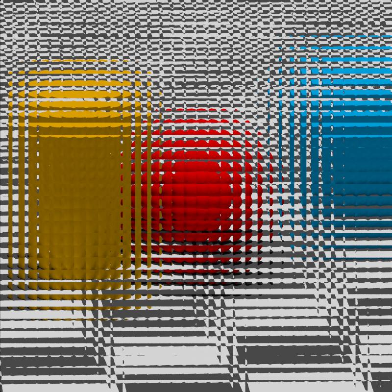
No, I'm not modeling "cross reed" glasses: see post by the same subject
on p.newusers ...

--
Jaime
Post a reply to this message
Attachments:
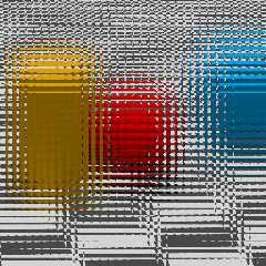
Download 'plenoptic-camera.jpg' (164 KB)
Preview of image 'plenoptic-camera.jpg'
|
|
| |
| |
|
|
|
|
| |
| |
|
|
Jaime Vives Piqueres <jai### [at] ignorancia org> wrote:
> No, I'm not modeling "cross reed" glasses: see post by the same subject
> on p.newusers ...
>
> --
> Jaime
Hmm, not seeing the post. Is this for use with integral imaging?
http://en.wikipedia.org/wiki/Integral_imaging
I was playing with integral imaging in POV just last year. It's a cool
technology, better than regular lenticular arrays or even most holograms, as the
cards can be rotated to any angle while still preserving their 3D appearance.
Rendering the source images in POV-Ray is super easy, although the resolution
must be very high.
Attached is one of my tests. You can cross your eyes at any two cards to view
the skull in 3D.
Sam org> wrote:
> No, I'm not modeling "cross reed" glasses: see post by the same subject
> on p.newusers ...
>
> --
> Jaime
Hmm, not seeing the post. Is this for use with integral imaging?
http://en.wikipedia.org/wiki/Integral_imaging
I was playing with integral imaging in POV just last year. It's a cool
technology, better than regular lenticular arrays or even most holograms, as the
cards can be rotated to any angle while still preserving their 3D appearance.
Rendering the source images in POV-Ray is super easy, although the resolution
must be very high.
Attached is one of my tests. You can cross your eyes at any two cards to view
the skull in 3D.
Sam
Post a reply to this message
Attachments:
Download 'iiskull3m_07s.jpg' (198 KB)
Preview of image 'iiskull3m_07s.jpg'

|
|
| |
| |
|
|
|
|
| |
| |
|
|
El 28/12/12 20:53, Samuel Benge escribió:
> Jaime Vives Piqueres <jai### [at] ignoranciaorg> wrote:
>> No, I'm not modeling "cross reed" glasses: see post by the same subject
>> on p.newusers ...
>>
>> --
>> Jaime
>
> Hmm, not seeing the post.

   Sorry, I changed the subject, but the original is "povray output as a
film/CCD" from 03/07/12 (I forgot not everyone uses a news reader setup
to display post ordered by date... :):

http://news.povray.org/povray.newusers/thread/%3Cweb.50009d33faf6826b9b0928190%40news.povray.org%3E/

> Is this for use with integral imaging?
> http://en.wikipedia.org/wiki/Integral_imaging

   No, that's apparently another interesting usage of light-fields. A
plenoptic camera takes images using a microlenses array, with the
purpose of being able to refocus the image after the fact (among other
things).

   http://en.wikipedia.org/wiki/Light-field_camera

--
Jaime
Post a reply to this message
|
|
| |
| |
|
|
|
|
| |
| |
|
|
Jaime Vives Piqueres <jai### [at] ignoranciaorg> wrote:
> No, I'm not modeling "cross reed" glasses: see post by the same subject
> on p.newusers ...
>
> --
> Jaime

Interesting and fine image. I wonder if really a mesh cam is needed here, but
have no time for tests myself. Should a usual cam within your mesh (may be
extruded into the -z direction for some amount, flattend and then properly
positioned) with a proper ior to the mesh not yield a similiar picture?

Best regards,
Michael
Post a reply to this message
|
|
| |
| |
|
|
|
|
| |
| |
|
|
El 29/12/12 21:50, MichaelJF escribió:
> Jaime Vives Piqueres <jai### [at] ignoranciaorg> wrote:
>> No, I'm not modeling "cross reed" glasses: see post by the same subject
>> on p.newusers ...
>>
>> --
>> Jaime
>
> Interesting and fine image. I wonder if really a mesh cam is needed here, but
> have no time for tests myself. Should a usual cam within your mesh (may be
> extruded into the -z direction for some amount, flattend and then properly
> positioned) with a proper ior to the mesh not yield a similiar picture?
>

  Yes, but the mesh_camera is much faster, and the result is much
smoother and resolution-independent. The only pain is that with
distribution #3 you cannot use more than one mesh (to stack some lenses).


--
Jaime
Post a reply to this message
|
|
| |
| |
|
|
|
|
| |
| |
|
|
Jaime Vives Piqueres <jai### [at] ignoranciaorg> wrote:
>   Yes, but the mesh_camera is much faster, and the result is much
> smoother and resolution-independent. The only pain is that with
> distribution #3 you cannot use more than one mesh (to stack some lenses).
>
>
> --
> Jaime

This was the reason to propose an other approach. I couldn't resist to test my
idea, but yielded only poor efforts (as you can see). But why not put the model
of a lense in front of the mesh cam?

Best regards,
Michael
Post a reply to this message
Attachments:
Download 'iortest.png' (189 KB)
Preview of image 'iortest.png'

|
|
| |
| |
|
|
|
|
| |
| |
|
|
"MichaelJF" <mi-### [at] t-onlinede> wrote:
> Jaime Vives Piqueres <jai### [at] ignoranciaorg> wrote:
> >   Yes, but the mesh_camera is much faster, and the result is much
> > smoother and resolution-independent. The only pain is that with
> > distribution #3 you cannot use more than one mesh (to stack some lenses).
> > --
> > Jaime
>
> This was the reason to propose an other approach. I couldn't resist to test my
> idea, but yielded only poor efforts (as you can see). But why not put the model
> of a lense in front of the mesh cam?
>
> Best regards,
> Michael

I might be missing something fundamental to the topic at hand (wouldn't be the
first time ;) ), but why not just place the following in front of the camera?

#declare ArrayRes = 96;
box{
 <-0.5, -0.5, 0>, <0.5, 0.5, 0>
 pigment{rgb 0 transmit 1}
 normal{
  function{
   (1-(x*x+y*y)/2)
  } -4*2
  translate x+y
  scale 1/2
  warp{repeat x}
  warp{repeat y}
  scale 1/ArrayRes
 }
 finish{diffuse 0}
 interior{ior 1.5}
 no_shadow no_reflection
}

That's what I used when rendering the light field for my integral imaging sim.
My first attempt for this step used actual geometry, but too many artifacts were
produced, so I settled on this quick-to-parse, fast-to-render solution.

Sam
Post a reply to this message
|
|
| |
| |
|
|
|
|
| |
| |
|
|
On 30/12/2012 7:35 PM, Samuel Benge wrote:
> I might be missing something fundamental to the topic at hand (wouldn't be the
> first time;)  ), but why not just place the following in front of the camera?

I must be missing it too. My thought was to use a camera Ray
Perturbation using a Leopard Normal. I am running an animation ATM
varying the scale.

--
Regards
     Stephen
Post a reply to this message
|
|
| |
| |
|
|
|
|
| |
| |
|
|
"Samuel Benge" <stb### [at] hotmailcom> wrote:

>
> I might be missing something fundamental to the topic at hand (wouldn't be the
> first time ;) ), but why not just place the following in front of the camera?
>
> #declare ArrayRes = 96;
> box{
>  <-0.5, -0.5, 0>, <0.5, 0.5, 0>
>  pigment{rgb 0 transmit 1}
>  normal{
>   function{
>    (1-(x*x+y*y)/2)
>   } -4*2
>   translate x+y
>   scale 1/2
>   warp{repeat x}
>   warp{repeat y}
>   scale 1/ArrayRes
>  }
>  finish{diffuse 0}
>  interior{ior 1.5}
>  no_shadow no_reflection
> }
>
> That's what I used when rendering the light field for my integral imaging sim.
> My first attempt for this step used actual geometry, but too many artifacts were
> produced, so I settled on this quick-to-parse, fast-to-render solution.
>
> Sam

I dont think that you are missing something here. My idea was the first I had in
my mind as I saw Jaimes picture. So I gave it a fast test. I think your idea and
Stephens may work better, but I came not up with this.

For me it was just a short and welcome distraction from more urgent RL issues.
Meanwhile I wonder why we simulate this camera at all. I learned about the
existence of plenoptic cameras by Jaimes posting first and found soon an article
from the Stanford group. As I understand it, their mean goal is to get more
depth of field with this camera as with an usual one. Didn't we have the problem
to get less DOF using focal blur? If one is intended in photorealistic rendering
of the results of an plenoptic camera, then this pictures must be heavily
postprocessed by analysing every field and composing an image from them. This
maths seems to be not trivial.

Best regards,
Michael
Post a reply to this message
|
|
| |
| |
|
|
|
|
| |
| |
|
|
El 01/01/13 17:54, MichaelJF escribió:
> For me it was just a short and welcome distraction from more urgent
> RL issues. Meanwhile I wonder why we simulate this camera at all. I
> learned about the existence of plenoptic cameras by Jaimes posting
> first and found soon an article from the Stanford group. As I
> understand it, their mean goal is to get more depth of field with
> this camera as with an usual one. Didn't we have the problem to get
> less DOF using focal blur? If one is intended in photorealistic
> rendering of the results of an plenoptic camera, then this pictures
> must be heavily postprocessed by analysing every field and composing
> an image from them. This maths seems to be not trivial.

   I explored this just because a guy asked for help simulating the
output of a plenoptic camera. I didn't get much information, but I guess
he is a researcher trying to validate his reconstruction or refocusing
algorithms in a cheap way, without having a real plenoptic camera at hand.

   And of course no, this isn't of much use for us, regular POVers...

--
Jaime
Post a reply to this message
|
|
| |
| |
|
|
|
|
| |
| |
|
|
El 30/12/12 20:35, Samuel Benge escribió:
> I might be missing something fundamental to the topic at hand (wouldn't be the
> first time ;) ), but why not just place the following in front of the camera?
>
> #declare ArrayRes = 96;
> box{
>   <-0.5, -0.5, 0>, <0.5, 0.5, 0>
>   pigment{rgb 0 transmit 1}
>   normal{
>    function{
>     (1-(x*x+y*y)/2)
>    } -4*2
>    translate x+y
>    scale 1/2
>    warp{repeat x}
>    warp{repeat y}
>    scale 1/ArrayRes
>   }
>   finish{diffuse 0}
>   interior{ior 1.5}
>   no_shadow no_reflection
> }
>
> That's what I used when rendering the light field for my integral imaging sim.
> My first attempt for this step used actual geometry, but too many artifacts were
> produced, so I settled on this quick-to-parse, fast-to-render solution.
>

   Yes, could work... I myself tried something similar with the camera
normal, but was not getting the exact lens geometry I wanted (my maths
are not soooo go), so I resorted to model it by hand on Wings3D: anyhow,
I would be using it with the mesh camera #3, so it will smooth the
normals and get ride of any triangle artifacts.

--
Jaime
Post a reply to this message
|
|
| |
| |
|
|
|
|
| |
| |
|
|
Stephen <mca### [at] aolcom> wrote:
>
> I must be missing it too. My thought was to use a camera Ray
> Perturbation using a Leopard Normal.

Hmm, is leopard really an appropriate pattern to use here? Isn't that pretty
much the cosine of x, y & z summed? I was forced to use the posted function only
after trying a cylindrical normal with poly_wave 0.5, and seeing how it didn't
work too well. The goal, of course, was to find something that would behave like
a spherical lens, but on a 2D surface.
Post a reply to this message
|
|
| |
| |
|
|
|
|
| |
| |
|
|
"MichaelJF" <mi-### [at] t-onlinede> wrote:
>
> Meanwhile I wonder why we simulate this camera at all.

In the words of George Mallory, "because it's there." :D

As for myself, I just wanted to play with integral imaging in POV. Even though
the idea has been a around for a while, the microlens array sheets still aren't
being developed. But when the manufacturing industry gets in line to start
producing the sheets, I'll have already developed a way to produce the source
images... using my favorite raytracer :)
Post a reply to this message
|
|
| |
| |
|
|
|
|
| |
| |
|
|
Jaime Vives Piqueres <jai### [at] ignoranciaorg> wrote:
> El 30/12/12 20:35, Samuel Benge escribió:
> > My first attempt for this step used actual geometry, but too many artifacts were
> > produced, so I settled on this quick-to-parse, fast-to-render solution.
>
>    Yes, could work... I myself tried something similar with the camera
> normal, but was not getting the exact lens geometry I wanted (my maths
> are not soooo go), so I resorted to model it by hand on Wings3D: anyhow,
> I would be using it with the mesh camera #3, so it will smooth the
> normals and get ride of any triangle artifacts.

I'm not sure I would trust meshes for this task; in fact, I'm sure I wouldn't.
I've seen too many optical artifacts produced by "smooth" meshes. No matter how
precise vertex normals are, they can never overcome the fact that a mesh is
still a mesh. A mesh representation of a smooth shape will never intersect space
the way a purely mathematical shape does.

Of course, all that doesn't account for the fact that I used a plane and not
real geometry, but I had my reasons ;)
Post a reply to this message
|
|
| |
| |
|
|
|
|
| |
| |
|
|
Samuel Benge wrote:
> the microlens array sheets still aren't being developed.
>
	Yes they are: https://en.wikipedia.org/wiki/Lytro

	I've had the occasion to play a little with one of these and I was
rather disappointed: the resulting resolution was very poor and the
possibilities of the provided software were pretty limited and far
from the demos they show on their web site :(

		Jerome
--
mailto:jeb### [at] freefr
http://jeberger.free.fr
Jabber: jeb### [at] jabberfr
Post a reply to this message
Attachments:
Download 'us-ascii' (1 KB)
|
|
| |
| |
|
|
|
|
| |
| |
|
|
=?UTF-8?B?IkrDqXLDtG1lIE0uIEJlcmdlciI=?= <jeberger@free.fr> wrote:
> Samuel Benge wrote:
> > the microlens array sheets still aren't being developed.
> >
>  Yes they are: https://en.wikipedia.org/wiki/Lytro

For cameras, yes, but what about integral imaging applications such as 3D
displays or "magic" cards? Last I heard, mass production of the sheets for
inexpensive products is still a ways off.

>  I've had the occasion to play a little with one of these and I was
> rather disappointed: the resulting resolution was very poor and the
> possibilities of the provided software were pretty limited and far
> from the demos they show on their web site :(

If integral imaging is any indication of what one can expect from those cameras,
I'm not surprised. It takes a very large source image to produce an end result.
In integral imaging, the final resolution (what you see) is directly
proportional to the number of sub-regions on the source image. The /angular/
resolution depends on the resolution of each sub-region of the source image. So,
if you want an image with an apparent pixel resolution of 1024x1024, and with an
angular resolution of 256x256 (65536 distinct points of view), your source image
needs to be 262144x262144 pixels. And that's just for an image that falls way
below print standards.

Still, the technology itself is very promising. Surveillance systems ala Blade
Runner (tweaking the view to see around objects) don't seem all that outlandish
anymore.
Post a reply to this message
|
|
| |
| |
|
|
|
|
| |
| |
|
|
Le 2013-01-01 13:55, Samuel Benge a écrit :
> Stephen <mca### [at] aolcom> wrote:
>>
>> I must be missing it too. My thought was to use a camera Ray
>> Perturbation using a Leopard Normal.
>
> Hmm, is leopard really an appropriate pattern to use here? Isn't that pretty
> much the cosine of x, y & z summed? I was forced to use the posted function only
> after trying a cylindrical normal with poly_wave 0.5, and seeing how it didn't
> work too well. The goal, of course, was to find something that would behave like
> a spherical lens, but on a 2D surface.
>
You may try the quilted pattern here.
Post a reply to this message
|
|
| |
| |
|
|
|
|
| |