|
|
|
|
|
|
| |
| |
|
|
|
|
| |
| |
|
|
This is definitely an example of the extent to which POV can be
mis-used...
Combining two of my hobbies, I've created a small include file that lets
you generate schematic diagrams of electronic circuits with POV-Ray. It
is basically a set of macros for making wires and component symbols.
It can currently draw:
NPN and PNP bipolar transistors
resistors
nonpolar and polar (electrolytic) capacitors
rectifier diodes
zener diodes
LEDs (Light Emitting Diodes)
Ground symbol
Wire connections
It can also automatically fit the schematic to the output image,
optionally leaving a blank margin area...if a component moves outside
the visible range, the entire schematic is scaled down until it fits,
while maintaining the proper aspect ratio. I also plan to add an
automatic labelling feature. Also, the schematic is currently done as a
texture on a box (using my object pattern patch), I will also try using
separate objects...that may be slower rendering, since POV will have to
do actual intersection calculations. Also, since it uses min_extent()
and max_extent, and the object pattern, it requires MegaPOV.
While it is probably useless for designing circuits, it could be useful
for illustrating them...it makes it easy to generate nicely anti-aliased
images at any resolution.
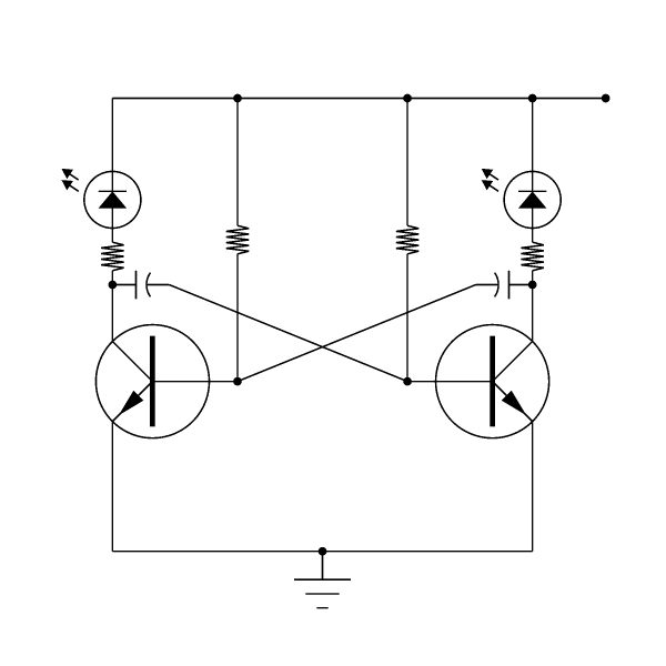
This is just a simple astable multivibrator LED flasher circuit. I used
a PNG because it wasn't any smaller as a JPEG, and JPEG left artifacts
visible.
--
Christopher James Huff
Personal: chr### [at] mac com, http://homepage.mac.com/chrishuff/
TAG: chr### [at] tagpovrayorg, http://tag.povray.org/
<>< com, http://homepage.mac.com/chrishuff/
TAG: chr### [at] tagpovrayorg, http://tag.povray.org/
<><
Post a reply to this message
Attachments:
Download 'Multivibrator.png' (14 KB)
Preview of image 'Multivibrator.png'
|
|
| |
| |
|
|
From: Tony[B]
Subject: Re: Electrical schematics include - Multivibrator.png (1/1)
Date: 19 Feb 2001 19:50:11
Message: <3a91bf43@news.povray.org>
|
|
|
| |
| |
|
|
Hey, that's cool, and definitely not a mis-use of POV. It just shows how
versatile it is. :)
Post a reply to this message
|
|
| |
| |
|
|
|
|
| |
| |
|
|
Chris Huff wrote:

> This is definitely an example of the extent to which POV can be
> mis-used...
> Combining two of my hobbies, I've created a small include file that lets
> you generate schematic diagrams of electronic circuits with POV-Ray. It
> is basically a set of macros for making wires and component symbols.
> It can currently draw:
> NPN and PNP bipolar transistors
> resistors
> nonpolar and polar (electrolytic) capacitors
> rectifier diodes
> zener diodes
> LEDs (Light Emitting Diodes)
> Ground symbol
> Wire connections
>
> It can also automatically fit the schematic to the output image,
> optionally leaving a blank margin area...if a component moves outside
> the visible range, the entire schematic is scaled down until it fits,
> while maintaining the proper aspect ratio. I also plan to add an
> automatic labelling feature. Also, the schematic is currently done as a
> texture on a box (using my object pattern patch), I will also try using
> separate objects...that may be slower rendering, since POV will have to
> do actual intersection calculations. Also, since it uses min_extent()
> and max_extent, and the object pattern, it requires MegaPOV.
> While it is probably useless for designing circuits, it could be useful
> for illustrating them...it makes it easy to generate nicely anti-aliased
> images at any resolution.
>
> This is just a simple astable multivibrator LED flasher circuit. I used
> a PNG because it wasn't any smaller as a JPEG, and JPEG left artifacts
> visible.
>
> --
> Christopher James Huff
> Personal: chr### [at] maccom, http://homepage.mac.com/chrishuff/
> TAG: chr### [at] tagpovrayorg, http://tag.povray.org/
>
> <><
>
>                         Name: Multivibrator.png
>    Multivibrator.png    Type: PNG Image (image/x-png)
>                     Encoding: x-uuencode

I thought that looked familiar, so I checked, and sure enough, it is an
exact duplicate of something I made.  I was in a 4H electronics club, and I
combined that circuit with an oscillator to make a siren that shines one
light when is goes up in pitch, and another light when it goes down in
pitch.  I won reserve champion at the county fair, and I got a blue ribbon
at state.  I was going to scan in the circuit diagram made on a plotter
using professional software for comparison.  Unfortunately the computer I
was going to use to scan the image wasn't showing anything on the screen due
to hardware failure, and it wasn't mine, so I didn't feel a need to get out
a screwdriver to fix it.  Anyway your image is much better than the one I
was going to scan.  Now what would be really cool is if you could take a
circuit diagram, and have it render a circuit board with accurate resistor
color codes, and everything.  I'm sure people would pay money for that.


--
Dan Johnson

http://www.geocities.com/zapob
Post a reply to this message
|
|
| |
| |
|
|
|
|
| |
| |
|
|
In article <3A91E60C.297BF165@hotmail.com>, Dan Johnson
<zap### [at] hotmailcom> wrote:

> I thought that looked familiar, so I checked, and sure enough, it is an
> exact duplicate of something I made.

The basic circuit (the two transistors linked together with capacitors)
is a pretty common building block, so it's not surprising that you have
seen it before if you have done anything at all with electronics.


> Now what would be really cool is if you could take a circuit diagram,
> and have it render a circuit board with accurate resistor color
> codes, and everything.  I'm sure people would pay money for that.

I'm sure people *do* pay money for software that does that...but I have
no idea how to do it. I'm having a hard enough time getting labels to
align properly. Doing something that used models of the parts would be
fairly easy, but the board traces would be next to impossible.

--
Christopher James Huff
Personal: chr### [at] maccom, http://homepage.mac.com/chrishuff/
TAG: chr### [at] tagpovrayorg, http://tag.povray.org/

<><
Post a reply to this message
|
|
| |
| |
|
|
|
|
| |
| |
|
|
On Tue, 20 Feb 2001 07:52:39 -0500, Chris Huff wrote:
>
>I'm sure people *do* pay money for software that does that...but I have
>no idea how to do it. I'm having a hard enough time getting labels to
>align properly. Doing something that used models of the parts would be
>fairly easy, but the board traces would be next to impossible.

Now Tony, there's a challenge if I ever saw one:-)

--
Cheers
Steve              email mailto:ste### [at] zeroppsuklinuxnet

%HAV-A-NICEDAY Error not enough coffee  0 pps.

web http://www.zeropps.uklinux.net/

or  http://start.at/zero-pps

  6:58pm  up 18 days, 20:38,  4 users,  load average: 1.00, 1.01, 1.00
Post a reply to this message
|
|
| |
| |
|
|
From: Tony[B]
Subject: Re: Electrical schematics include - Multivibrator.png (1/1)
Date: 21 Feb 2001 23:12:05
Message: <3a949195@news.povray.org>
|
|
|
| |
| |
|
|
:o How did I get into this? Why is this a challenge to me?
Post a reply to this message
|
|
| |
| |
|
|
|
|
| |
| |
|
|
"Tony[B]" wrote:

> :o How did I get into this? Why is this a challenge to me?

Hey just found something that might be in interest.  A finished circuit
board, and schematic made in povray.

http://ourworld.compuserve.com/homepages/Alf_Peake/PC-BOARD.JPG


--
Dan Johnson

http://www.geocities.com/zapob
Post a reply to this message
|
|
| |
| |
|
|
|
|
| |
| |
|
|
In article <3A959023.DEC3722F@hotmail.com>, Dan Johnson
<zap### [at] hotmailcom> wrote:

> Hey just found something that might be in interest.  A finished circuit
> board, and schematic made in povray.
>
> http://ourworld.compuserve.com/homepages/Alf_Peake/PC-BOARD.JPG

I remember seeing that before...I think it was posted here.
Hmm, what is it? (Mr. Peake, you reading this?)
The bridge rectifier, large capacitors, and 7808 voltage regulator make
a regulated 8V power supply that takes an AC input, and there seems to
be an option to use a battery as a power source as well, but I don't
recognize the 8-pin DIP IC. That and the other components don't look
like they belong on a power-supply board. There is something labelled
"door"...maybe a trigger for a garage door opener, or an alarm for when
a door gets opened, or a doorbell. The last two make the most sense...

I think he used image_maps for the part numbers and art, and maybe a
height_field for the copper traces (it looks slightly raised)...that
kind of stuff would be a lot easier now, you could use the object
pattern and create a set of macros that makes a generic IC, capacitor,
transistor, etc. and puts the specified text/other art on it, instead of
redoing much of it for each new part. And the schematic looks like it
was hand drawn, then scanned in as 1-bit color.

BTW, I have thought about it some more, and I think it would be possible
to do a simple kind of PC board layout with my macros...it would be
limited to a single-sided board, you would have to manually place
jumpers where the traces need to cross, and the layout of the components
would follow the layout of the schematic, which is rarely the best way
to do things and means you may have to adjust things to make sure
components don't intrude on each other's space, but it should work. I'll
save it for version 2, though...

--
Christopher James Huff
Personal: chr### [at] maccom, http://homepage.mac.com/chrishuff/
TAG: chr### [at] tagpovrayorg, http://tag.povray.org/

<><
Post a reply to this message
|
|
| |
| |
|
|
From: Mark Wagner
Subject: Re: Electrical schematics include - Multivibrator.png (1/1)
Date: 23 Feb 2001 02:04:35
Message: <3a960b83@news.povray.org>
|
|
|
| |
| |
|
|
Chris Huff wrote in message ...
>...but I don't
>recognize the 8-pin DIP IC. That and the other components don't look
>like they belong on a power-supply board. There is something labelled
>"door"...maybe a trigger for a garage door opener, or an alarm for when
>a door gets opened, or a doorbell. The last two make the most sense...


It appears to be a doorbell.  According to the Chip Directory, the 2811 IC
is:

2811    HT-2811    sound    Door Bell, Ding Dong    Holtek*

(The Chip Directory is at
http://www.xs4all.nl/~ganswijk/chipdir/index.html).
--
Mark
Post a reply to this message
|
|
| |
| |
|
|
|
|
| |
| |
|
|
In article <3a960b83@news.povray.org>, "Mark Wagner"
<mar### [at] gtenet> wrote:

> It appears to be a doorbell.  According to the Chip Directory, the 2811 IC
> is:
> 2811    HT-2811    sound    Door Bell, Ding Dong    Holtek*
> (The Chip Directory is at
> http://www.xs4all.nl/~ganswijk/chipdir/index.html).

I identified the chip later, with a Google search. ;-)
I find the Chip Directory is often frusterating for identifying strange
chips, though it is sometimes helpful. Some of the chips I find are just
very...obscure.
(are we off-topic yet?)

--
Christopher James Huff
Personal: chr### [at] maccom, http://homepage.mac.com/chrishuff/
TAG: chr### [at] tagpovrayorg, http://tag.povray.org/

<><
Post a reply to this message
|
|
| |
| |
|
|
From: Alf Peake
Subject: Re: Electrical schematics include - Multivibrator.png (1/1)
Date: 24 Feb 2001 18:34:18
Message: <3a9844fa@news.povray.org>
|
|
|
| |
| |
|
|
"Chris Huff" <chr### [at] maccom> wrote in message
news:chrishuff-4168E1.18192122022001@news.povray.org...
> In article <3A959023.DEC3722F@hotmail.com>, Dan Johnson
> <zap### [at] hotmailcom> wrote:
>
> > Hey just found something that might be in interest.  A finished
circuit
> > board, and schematic made in povray.
> >
> > http://ourworld.compuserve.com/homepages/Alf_Peake/PC-BOARD.JPG
>
> I remember seeing that before...I think it was posted here.
> Hmm, what is it? (Mr. Peake, you reading this?)

Yes Mr. Huff :-), I think I posted it on Compuserve a few years ago
but not here.

[snip]
> "door"...maybe a trigger for a garage door opener, or an alarm for
when
> a door gets opened, or a doorbell. The last two make the most
sense...

Bingo! We have a winner. A door bell kit from Maplin many years ago to
replace one that got zapped by lightning.

>
> I think he used image_maps for the part numbers and art, and maybe a
> height_field for the copper traces (it looks slightly raised)...that

Part numbers done with PSPro. The Cu track was scanned with a hand
scanner (hi-tech then), then used as a HF. Needed to accentuate the Cu
height for non-techies ;-)

[snip]
> redoing much of it for each new part. And the schematic looks like
it
> was hand drawn, then scanned in as 1-bit color.

A Logitech 4-bit BW hand scanner on the supplied schematic. Took 3
scan strips if I remember, then was image_mapped onto a bozo HF. 1-bit
coz 4-bits was way to large a file then.

[snip]
>
> --
> Christopher James Huff

--
Alf

http://www.peake42.freeserve.co.uk/
http://ourworld.compuserve.com/homepages/Alf_Peake/
gw3### [at] thersgbnet
Post a reply to this message
|
|
| |
| |
|
|
From: Alf Peake
Subject: Re: Electrical schematics include - Multivibrator.png (1/1)
Date: 24 Feb 2001 18:34:20
Message: <3a9844fc@news.povray.org>
|
|
|
| |
| |
|
|
"Mark Wagner" <mar### [at] gtenet> wrote in message
news:3a960b83@news.povray.org...
> Chris Huff wrote in message ...
> >...but I don't
> >recognize the 8-pin DIP IC. That and the other components don't
look
> >like they belong on a power-supply board. There is something
labelled
> >"door"...maybe a trigger for a garage door opener, or an alarm for
when
> >a door gets opened, or a doorbell. The last two make the most
sense...
>
>
> It appears to be a doorbell.  According to the Chip Directory, the
2811 IC
> is:
>
> 2811    HT-2811    sound    Door Bell, Ding Dong    Holtek*
>

That's right, and the onboard rectifier allows for battery or "bell
txformer" operation.


--
Alf

http://www.peake42.freeserve.co.uk/
http://ourworld.compuserve.com/homepages/Alf_Peake/
gw3### [at] thersgbnet
Post a reply to this message
|
|
| |
| |
|
|
|
|
| |
| |
|
|
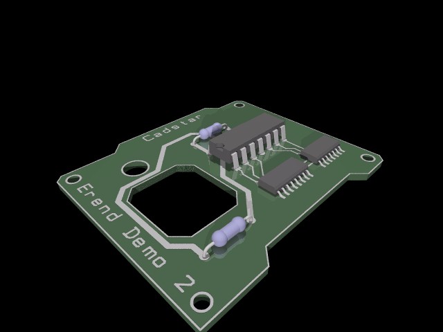
Chris Huff wrote:


> Doing something that used models of the parts would be
> fairly easy, but the board traces would be next to impossible.

With the right tools nothing is impossible :)

--
Ken Tyler
Post a reply to this message
Attachments:
Download 'demo2.jpg' (31 KB)
Preview of image 'demo2.jpg'
|
|
| |
| |
|
|
From: Tony[B]
Subject: Re: Electrical schematics include - Multivibrator.png (1/1)
Date: 1 Mar 2001 15:16:49
Message: <3a9eae31@news.povray.org>
|
|
|
| |
| |
|
|
Cheater! :)
Post a reply to this message
|
|
| |
| |
|
|
|
|
| |
| |
|
|
Post a reply to this message
|
|
| |
| |
|
|
|
|
| |
| |
|
|
In article <3A9EA03C.8B4B5E1C@pacbell.net>, lin### [at] povrayorg
wrote:

> > Doing something that used models of the parts would be
> > fairly easy, but the board traces would be next to impossible.
>
> With the right tools nothing is impossible :)

Um, is this entirely within POV, or did you use an external utility?
("Cadstar"?)

I was referring to the difficulty of building this capability *into the
include file*. I'm aware there are other programs that can do it, but
doing it in POV-Script would be difficult. (though I can probably figure
out a fairly limited method...)

--
Christopher James Huff
Personal: chr### [at] maccom, http://homepage.mac.com/chrishuff/
TAG: chr### [at] tagpovrayorg, http://tag.povray.org/

<><
Post a reply to this message
|
|
| |
| |
|
|
|
|
| |
| |
|
|
Post a reply to this message
|
|
| |
| |
|
|
From: Tony[B]
Subject: Re: Electrical schematics include - Multivibrator.png (1/1)
Date: 1 Mar 2001 20:27:52
Message: <3a9ef718@news.povray.org>
|
|
|
| |
| |
|
|
Couldn't you just break a spline down into linear segments?
Post a reply to this message
|
|
| |
| |
|
|
|
|
| |
| |
|
|
In article <3a9ef718@news.povray.org>, "Tony[B]" <ben### [at] catholicorg>
wrote:

> Couldn't you just break a spline down into linear segments?

Huh?
Were you trying to reply to a different message?

--
Christopher James Huff
Personal: chr### [at] maccom, http://homepage.mac.com/chrishuff/
TAG: chr### [at] tagpovrayorg, http://tag.povray.org/

<><
Post a reply to this message
|
|
| |
| |
|
|
From: Tony[B]
Subject: Re: Electrical schematics include - Multivibrator.png (1/1)
Date: 2 Mar 2001 08:54:24
Message: <3a9fa610@news.povray.org>
|
|
|
| |
| |
|
|
No, I was suggesting how you could do the traces, using boxes and splines
broken down into linear segments... or am I totally lost?
Post a reply to this message
|
|
| |
| |
|
|
|
|
| |
| |
|
|
In article <3a9fa610@news.povray.org>, "Tony[B]" <ben### [at] catholicorg>
wrote:

> No, I was suggesting how you could do the traces, using boxes and splines
> broken down into linear segments... or am I totally lost?

You've certainly lost me...making the traces isn't the problem, the
problem is positioning the traces so they don't intersect or contact,
and positioning the components to fit on the board. I can probably make
a different mode for the include file that will do all this, putting the
traces on one side of the board with jumpers to cross over and using
models of actual components, but schematics will likely require manual
adjustment because the positioning of the component model terminals will
be different from the symbol terminals.

--
Christopher James Huff
Personal: chr### [at] maccom, http://homepage.mac.com/chrishuff/
TAG: chr### [at] tagpovrayorg, http://tag.povray.org/

<><
Post a reply to this message
|
|
| |
| |
|
|
From: Tony[B]
Subject: Re: Electrical schematics include - Multivibrator.png (1/1)
Date: 2 Mar 2001 20:40:03
Message: <3aa04b73@news.povray.org>
|
|
|
| |
| |
|
|
>the problem is positioning the traces
>so they don't intersect or contact,

Shouldn't that be the job of the user? Just give 'em a macro that makes the
traces and let them worry about them interesecting or not.
Post a reply to this message
|
|
| |
| |
|
|
|
|
| |
| |
|
|
In article <3aa04b73@news.povray.org>, "Tony[B]" <ben### [at] catholicorg>
wrote:

> Shouldn't that be the job of the user?

Not when the whole point of the feature is that the user doesn't have to
do it...


> Just give 'em a macro that makes the traces and let them worry about
> them interesecting or not.

That's currently all that exists.

--
Christopher James Huff
Personal: chr### [at] maccom, http://homepage.mac.com/chrishuff/
TAG: chr### [at] tagpovrayorg, http://tag.povray.org/

<><
Post a reply to this message
|
|
| |
| |
|
|
|
|
| |