|
|
|
|
|
|
| |
| |
|
|
|
|
| |
| |
|
|
Hi
The attached animation shows 5 x 3 = 15 animated bivariate patches.
Each patch is drawn "within" a trivariate (u, v, w) whose control grid consists
of 3x3x3 = 27 points.
Each patch is drawn by varying both the v and w parameters of the trivariate
from 0.0 to 1.0, while the animation clock, running from 0.0 to 1.0, is
controlling the u parameter.
This is analogous to what happens in this animation:
https://dataduppedings.no/subcube/POV-Ray/NURBS-Quadrivariate_Deformation.mpg
Here all the boxes are drawn "within" a quadrivariate (u, v, w, t), where the
animation clock controls the t parameter.
--
Tor Olav
http://subcube.com
https://github.com/t-o-k
Post a reply to this message
Attachments:
Download 'trivariaterationalbezierpatches.mp4.dat' (3441 KB)
|
|
| |
| |
|
|
|
|
| |
| |
|
|
Hi TOK,
I'll have to wait until I'm home to access dataduppedings.no/
But in the meantime,
> The attached animation shows 5 x 3 = 15 animated bivariate patches.
> Each patch is drawn "within" a trivariate (u, v, w) whose control grid consists
> of 3x3x3 = 27 points.
So, they are quadratic Bezier surfaces?
> Each patch is drawn by varying both the v and w parameters of the trivariate
> from 0.0 to 1.0, while the animation clock, running from 0.0 to 1.0, is
> controlling the u parameter.
and then the u parameter gets interpolated between its 3 control points along an
"orthogonal" quadratic Bezier spline. And I'm assuming that v and w are
parametric equations of u.
That's pretty cool.
Have you thought about geometrically inverting the patches to become a cylinder
or a cone? :D
- BW
Post a reply to this message
|
|
| |
| |
|
|
From: William F Pokorny
Subject: Re: Some bivariate slices of rational Bezier trivariates
Date: 26 Mar 2025 10:45:14
Message: <67e412fa$1@news.povray.org>
|
|
|
| |
| |
|
|
On 3/26/25 07:48, Tor Olav Kristensen wrote:
> Here all the boxes are drawn "within" a quadrivariate (u, v, w, t), where the
> animation clock controls the t parameter.
I like it! Cool.
Bill P.
Post a reply to this message
|
|
| |
| |
|
|
|
|
| |
| |
|
|
"Bald Eagle" <cre### [at] netscape net> wrote:
> Hi TOK,
> I'll have to wait until I'm home to access dataduppedings.no/
>
> But in the meantime,
>
> > The attached animation shows 5 x 3 = 15 animated bivariate patches.
> > Each patch is drawn "within" a trivariate (u, v, w) whose control grid consists
> > of 3x3x3 = 27 points.
>
> So, they are quadratic Bezier surfaces?
Yes, rational quadratic Bezier surfaces.
> > Each patch is drawn by varying both the v and w parameters of the trivariate
> > from 0.0 to 1.0, while the animation clock, running from 0.0 to 1.0, is
> > controlling the u parameter.
>
> and then the u parameter gets interpolated between its 3 control points along an
> "orthogonal" quadratic Bezier spline. And I'm assuming that v and w are
> parametric equations of u.
The corners of the patches are influenced by 3 points only - and
the edges of the patches are influenced by 9 points.
But elsewhere in the patches all 27 control points are used in the
calculations (if I have understood this correctly).
And v and w are not parametric equations of u.
Here's some untested and non optimal code that shows the roles of
u, v and w:
#declare QuadraticBlendFns =
array[3] {
function(s) { (1 - s)*(1 - s) },
function(s) { (1 - s)*s },
function(s) { s*s }
}
;
#macro TrivariateQuadraticBezierFunction(CC)
function(_u, _v, _w) {
0.0
#for (K, 0, 2)
#for (J, 0, 2)
#for (I, 0, 2)
+
QuadraticBlendFns[I](_u)
*
QuadraticBlendFns[J](_v)
*
QuadraticBlendFns[K](_w)
*
CC[I][J][K]
#end // for
#end // for
#end // for
}
#end // macro TrivariateQuadraticBezierFunction
> That's pretty cool.
Thank you =)
> Have you thought about geometrically inverting the patches to become a cylinder
> or a cone? :D
I'm not sure what you mean by "inverting the patches".
I have not yet made cones with Bezier patches. But I have made
cylinders. This document shows an example:
https://github.com/t-o-k/Maxima-bezier/blob/main/cylinder_made_with_4_rational_bezier_surfaces_3d.pdf
Here's some more untested code that shows how to use the clock
to "slice" the trivariate functions into bivariate functions.
XX, YY and ZZ are 3x3x3 arrays with the X, Y and coordinates
of the 3x3x3 control points.
#declare TrivariateFnX = TrivariateQuadraticBezierFunction(XX);
#declare TrivariateFnY = TrivariateQuadraticBezierFunction(YY);
#declare TrivariateFnZ = TrivariateQuadraticBezierFunction(ZZ);
#declare U = clock;
#declare BivariateFnX = function(_v, _w) { TrivariateFnX(U, _v, _w) };
#declare BivariateFnY = function(_v, _w) { TrivariateFnY(U, _v, _w) };
#declare BivariateFnZ = function(_v, _w) { TrivariateFnZ(U, _v, _w) };
#declare dV = 1/100;
#declare dW = 1/100;
#declare AnimatedMesh =
mesh {
#declare W0 = 0.0;
#for (K, 1, 100)
#declare W1 = W0 + dW;
#declare V0 = 0.0;
#for (J, 1, 100)
#declare V1 = V0 + dV;
#declare p00 =
<
BivariateFnX(V0, W0),
BivariateFnY(V0, W0),
BivariateFnZ(V0, W0)
>
;
#declare p01 =
<
BivariateFnX(V0, W1),
BivariateFnY(V0, W1),
BivariateFnZ(V0, W1)
>
;
#declare p10 =
<
BivariateFnX(V1, W0),
BivariateFnY(V1, W0),
BivariateFnZ(V1, W0)
>
;
#declare p11 =
<
BivariateFnX(V1, W1),
BivariateFnY(V1, W1),
BivariateFnZ(V1, W1)
>
;
triangle { p00, p10, p11 }
triangle { p11, p01, p00 }
#declare V0 = V1;
#end // for
#declare W0 = W1;
#end // for
}
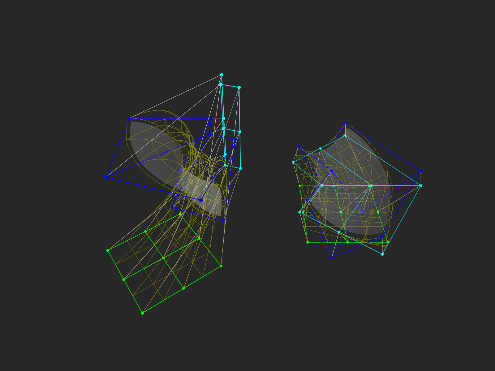
The attached image shows the 3x3x3 = 3x9 = 27 control points for
two of the patches in the animation. Note that the patches do
not get very close to the 9 cyan "intermediate" control points.
--
Tor Olav
http://subcube.com
https://github.com/t-o-k net> wrote:
> Hi TOK,
> I'll have to wait until I'm home to access dataduppedings.no/
>
> But in the meantime,
>
> > The attached animation shows 5 x 3 = 15 animated bivariate patches.
> > Each patch is drawn "within" a trivariate (u, v, w) whose control grid consists
> > of 3x3x3 = 27 points.
>
> So, they are quadratic Bezier surfaces?
Yes, rational quadratic Bezier surfaces.
> > Each patch is drawn by varying both the v and w parameters of the trivariate
> > from 0.0 to 1.0, while the animation clock, running from 0.0 to 1.0, is
> > controlling the u parameter.
>
> and then the u parameter gets interpolated between its 3 control points along an
> "orthogonal" quadratic Bezier spline. And I'm assuming that v and w are
> parametric equations of u.
The corners of the patches are influenced by 3 points only - and
the edges of the patches are influenced by 9 points.
But elsewhere in the patches all 27 control points are used in the
calculations (if I have understood this correctly).
And v and w are not parametric equations of u.
Here's some untested and non optimal code that shows the roles of
u, v and w:
#declare QuadraticBlendFns =
array[3] {
function(s) { (1 - s)*(1 - s) },
function(s) { (1 - s)*s },
function(s) { s*s }
}
;
#macro TrivariateQuadraticBezierFunction(CC)
function(_u, _v, _w) {
0.0
#for (K, 0, 2)
#for (J, 0, 2)
#for (I, 0, 2)
+
QuadraticBlendFns[I](_u)
*
QuadraticBlendFns[J](_v)
*
QuadraticBlendFns[K](_w)
*
CC[I][J][K]
#end // for
#end // for
#end // for
}
#end // macro TrivariateQuadraticBezierFunction
> That's pretty cool.
Thank you =)
> Have you thought about geometrically inverting the patches to become a cylinder
> or a cone? :D
I'm not sure what you mean by "inverting the patches".
I have not yet made cones with Bezier patches. But I have made
cylinders. This document shows an example:
https://github.com/t-o-k/Maxima-bezier/blob/main/cylinder_made_with_4_rational_bezier_surfaces_3d.pdf
Here's some more untested code that shows how to use the clock
to "slice" the trivariate functions into bivariate functions.
XX, YY and ZZ are 3x3x3 arrays with the X, Y and coordinates
of the 3x3x3 control points.
#declare TrivariateFnX = TrivariateQuadraticBezierFunction(XX);
#declare TrivariateFnY = TrivariateQuadraticBezierFunction(YY);
#declare TrivariateFnZ = TrivariateQuadraticBezierFunction(ZZ);
#declare U = clock;
#declare BivariateFnX = function(_v, _w) { TrivariateFnX(U, _v, _w) };
#declare BivariateFnY = function(_v, _w) { TrivariateFnY(U, _v, _w) };
#declare BivariateFnZ = function(_v, _w) { TrivariateFnZ(U, _v, _w) };
#declare dV = 1/100;
#declare dW = 1/100;
#declare AnimatedMesh =
mesh {
#declare W0 = 0.0;
#for (K, 1, 100)
#declare W1 = W0 + dW;
#declare V0 = 0.0;
#for (J, 1, 100)
#declare V1 = V0 + dV;
#declare p00 =
<
BivariateFnX(V0, W0),
BivariateFnY(V0, W0),
BivariateFnZ(V0, W0)
>
;
#declare p01 =
<
BivariateFnX(V0, W1),
BivariateFnY(V0, W1),
BivariateFnZ(V0, W1)
>
;
#declare p10 =
<
BivariateFnX(V1, W0),
BivariateFnY(V1, W0),
BivariateFnZ(V1, W0)
>
;
#declare p11 =
<
BivariateFnX(V1, W1),
BivariateFnY(V1, W1),
BivariateFnZ(V1, W1)
>
;
triangle { p00, p10, p11 }
triangle { p11, p01, p00 }
#declare V0 = V1;
#end // for
#declare W0 = W1;
#end // for
}
The attached image shows the 3x3x3 = 3x9 = 27 control points for
two of the patches in the animation. Note that the patches do
not get very close to the 9 cyan "intermediate" control points.
--
Tor Olav
http://subcube.com
https://github.com/t-o-k
Post a reply to this message
Attachments:
Download 'rational_bezier_control_grids.png' (350 KB)
Preview of image 'rational_bezier_control_grids.png'
|
|
| |
| |
|
|
|
|
| |
| |
|
|
William F Pokorny <ano### [at] anonymousorg> wrote:
> On 3/26/25 07:48, Tor Olav Kristensen wrote:
> > Here all the boxes are drawn "within" a quadrivariate (u, v, w, t), where the
> > animation clock controls the t parameter.
>
> I like it! Cool.
Thank you Bill!
--
Tor Olav
http://subcube.com
https://github.com/t-o-k
Post a reply to this message
|
|
| |
| |
|
|
|
|
| |
| |
|
|
"Tor Olav Kristensen" <tor### [at] TOBEREMOVEDgmailcom> wrote:
> > Have you thought about geometrically inverting the patches to become a cylinder
> > or a cone? :D
>
> I'm not sure what you mean by "inverting the patches".
>
> I have not yet made cones with Bezier patches. But I have made
> cylinders. This document shows an example:
>
>
https://github.com/t-o-k/Maxima-bezier/blob/main/cylinder_made_with_4_rational_bezier_surfaces_3d.pdf
https://en.wikipedia.org/wiki/Dupin_cyclide#Dupin_cyclides_and_geometric_inversions
So you could start with a cylinder, invert it into a torus, and then re-invert
it into a cone. :D Invert it again into a Dupin cyclide, and then you could
invert a final time back to the original cylinder and have QUITE the cyclic
animation!
> The attached image shows the 3x3x3 = 3x9 = 27 control points for
> two of the patches in the animation. Note that the patches do
> not get very close to the 9 cyan "intermediate" control points.
Ah yes - that makes it much clearer.
Though if you're interpolating between control grids composed of u,w
coordinates, via splines controlled by u, then technically u and w are
parametric equations in u even not explicitly written that way. Right? (?)
Beautiful work as always.
I always enjoy the ballet of the math and graphics, and admire and appreciate
the skill and discipline to make it all happen.
I'm glad you had the free time to put this one together. :)
- BW
Post a reply to this message
|
|
| |
| |
|
|
|
|
| |
| |
|
|
"Bald Eagle" <cre### [at] netscapenet> wrote:
> "Tor Olav Kristensen" <tor### [at] TOBEREMOVEDgmailcom> wrote:
>
> > > Have you thought about geometrically inverting the patches to become a cylinder
> > > or a cone? :D
> >
> > I'm not sure what you mean by "inverting the patches".
> >
> > I have not yet made cones with Bezier patches. But I have made
> > cylinders. This document shows an example:
> >
> >
https://github.com/t-o-k/Maxima-bezier/blob/main/cylinder_made_with_4_rational_bezier_surfaces_3d.pdf
>
> https://en.wikipedia.org/wiki/Dupin_cyclide#Dupin_cyclides_and_geometric_inversions
That's some interesting transforms.
It would be an interesting exercise to experiment with them.
> So you could start with a cylinder, invert it into a torus, and then re-invert
> it into a cone. :D Invert it again into a Dupin cyclide, and then you could
> invert a final time back to the original cylinder and have QUITE the cyclic
> animation!
>
> > The attached image shows the 3x3x3 = 3x9 = 27 control points for
> > two of the patches in the animation. Note that the patches do
> > not get very close to the 9 cyan "intermediate" control points.
>
> Ah yes - that makes it much clearer.
>
> Though if you're interpolating between control grids composed of u,w
> coordinates, via splines controlled by u, then technically u and w are
> parametric equations in u even not explicitly written that way. Right? (?)
I'm not sure if I'm able to follow your line of thinking - sorry.
You can hold any of u, v and w constant and then vary the remaining
ones with code or by the clock. The result could be a point, a curve,
a patch or a kind of "solid".
E.g.:
If you let u be a constant, let v be controlled by the clock - and
vary w with some code, then a bicubic Bezier curve that wiggles
around within the 3x3x3 grid can be shown (in an animation).
> Beautiful work as always.
> I always enjoy the ballet of the math and graphics, and admire and appreciate
> the skill and discipline to make it all happen.
>
> I'm glad you had the free time to put this one together. :)
Thank you very much Bill!
=)
--
Tor Olav
http://subcube.com
https://github.com/t-o-k
Post a reply to this message
|
|
| |
| |
|
|
|
|
| |
| |
|
|
"Tor Olav Kristensen" <tor### [at] TOBEREMOVEDgmailcom> wrote:
https://en.wikipedia.org/wiki/Dupin_cyclide#Dupin_cyclides_and_geometric_inversions
>
> That's some interesting transforms.
>
> It would be an interesting exercise to experiment with them.
I think you get a lot of bang for your buck.
Check out the "Pappus Chain" thread.
> > So you could start with a cylinder, invert it into a torus, and then re-invert
> > it into a cone. :D Invert it again into a Dupin cyclide, and then you could
> > invert a final time back to the original cylinder and have QUITE the cyclic
> > animation!
> I'm not sure if I'm able to follow your line of thinking - sorry.
If you follow the diagrams, you'll see that the inversion sphere is a kind of
geometric mirror. And depending upon how the shape and sphere are oriented to
one another, you can get different results. It's quite the "fun house" mirror.
So my thought was:
A Dupin cyclide can be obtained by inversion of either a ring torus, a cylinder,
or a cone.
Start with a ring torus and invert it to a Dupin cyclide through the appropriate
inversion sphere.
But now, since a Dupin cyclide can be inverted to a cylinder, invert it through
a different sphere to get the cylinder.
Then invert it back to a different Dupin cyclide with yet another inversion
sphere,
and then invert it to a cone with another sphere.
That can be inverted to a Dupin cyclide again,
which can be inverted to the original ring torus.
The real trick is to calculate the parameters of the shapes and the inversion
sphere to get the desired shapes upon each new inversion.
> You can hold any of u, v and w constant and then vary the remaining
> ones with code or by the clock. The result could be a point, a curve,
> a patch or a kind of "solid".
OK, I think I had plain vanilla Bezier surfaces in my mind when you were working
with rational (weighted) Bezier patches.
I will now return you to your regularly scheduled programming. :)
- BW
Post a reply to this message
|
|
| |
| |
|
|
|
|
| |
|
|