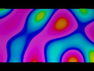
|
 |
Stephen <mca### [at] aol com> wrote:
> Nice and that is using bicubic patches?
No sir. Still too ignorant and unskilled to make that happen, but had a number
of breakthroughs yesterday, and hopefully will get some bicubic patch code
cobbled together as a proof-of-concept. Then it ought to be much smoother and
prettier.
> I processed the data (deviation from the average) and used triangles to
> make the plate.
I used the raw data, since there was no information indicating that the plate
was flat, and so it looks like it's vibrations in a stressed plate.
I'm going to give some thought to finding vibrational nodes and have the edges
flex freely using those as the true stationary points.
Given time, talent, inspiration, freedom from interruption, plenty of coffee,
and tips and helpful feedback from the helpful folks here in POV-Land. com> wrote:
> Nice and that is using bicubic patches?
No sir. Still too ignorant and unskilled to make that happen, but had a number
of breakthroughs yesterday, and hopefully will get some bicubic patch code
cobbled together as a proof-of-concept. Then it ought to be much smoother and
prettier.
> I processed the data (deviation from the average) and used triangles to
> make the plate.
I used the raw data, since there was no information indicating that the plate
was flat, and so it looks like it's vibrations in a stressed plate.
I'm going to give some thought to finding vibrational nodes and have the edges
flex freely using those as the true stationary points.
Given time, talent, inspiration, freedom from interruption, plenty of coffee,
and tips and helpful feedback from the helpful folks here in POV-Land.
Post a reply to this message
|
 |
|
 |
So, I'm trying to work through in my head what the best way to model this is,
with the amplitudes and the times, and the measurement points, and the
intermediate control points of the patch.
I started to model the plate as an isosurface of interfering cosine waves, which
was humming along as smoothly as I could have hoped, and then my function
started throwing errors.
Once I commented out the additional parameters, it was fine.
Is there some upper limit to how much stuff you can stuff into a function?
############################################################################
#version 3.7;
global_settings { assumed_gamma 1.0 }
//------------------------------------------
// SDL for
// Bill Walker - 2016
//------------------------------------------
#include "colors.inc"
#include "debug.inc"
Set_Debug (true)
#include "math.inc"
#include "TempGradient.inc"
light_source { <0, 50, -50> color rgb <1, 1, 1>}
#declare Camera_Front = camera {
location <0, 75, -1>
//right x*image_width/image_height
look_at <0, 0, 0>}
camera {Camera_Front}
#declare Y = 0;
#declare PW = 56.378/2;
#declare r=125;
// amplitudes based on 1st 150 points, max-min
#declare A4 = 0.007;
#declare A6 = 0.015;
#declare A2 = 0.006;
#declare A7 = 0.009;
#declare A10 = 0.009;
#declare A9 = 0.011;
#declare Point2 = <-00.9, -0.106, PW>;
#declare P2 = Point2.x;
#declare Point4 = < 50.0, -0.037, 0>;
#declare P4 = Point4.x;
#declare Point6 = < 28.0, 0.048, -PW>;
#declare P6 = Point6.x;
#declare Point7 = <-22.0, -0.033, -PW>;
#declare P7 = Point7.x;
#declare Point9 = <-50.0, 0.01, -19.8>;
#declare P7 = Point9.x;
#declare Point10 = <-50.0, 0.075, PW-21.9>;
#declare Z10 = PW - 21.9;
#declare P7 = Point10.x;
#declare Freq = 0.05;
isosurface{ //------------------------- "sombrero"
function{ y -
A2 * cos(sqrt(pow(x, 2) - (2*P2*x) + pow(P2, 2) + pow(z, 2) - (2*PW*z) +
pow(PW, 2))*Freq*pi) +
A4 * cos(sqrt(pow(x, 2) - (2*P4*x) + pow(P4, 2) + pow(z, 2) - (2*0*z) +
pow(0, 2)) *Freq*pi) +
A6 * cos(sqrt(pow(x, 2) - (2*P6*x) + pow(P6, 2) + pow(z, 2) - (2*-PW*z) +
pow(PW, 2))*Freq*pi) +
A7 * cos(sqrt(pow(x, 2) - (2*P7*x) + pow(P7, 2) + pow(z, 2) - (2*-PW*z) +
pow(PW, 2))*Freq*pi) //+
//A9 * cos(sqrt(pow(x, 2) - (2*P9*x) + pow(P9, 2) + pow(z, 2) + (2*19.8*z) +
pow(19.8, 2))*Freq*pi) +
//A10 * cos(sqrt(pow(x, 2) - (2*P10*x) + pow(P10, 2) + pow(z, 2) - (2*Z10*z) +
pow(Z10, 2))*Freq*pi)
}
threshold 0
contained_by{box{<-50, -1, -PW>, <50, 1, PW>}}
texture{
pigment{ TempGradient scale <1, 0.08, 1>}
//normal { ripples 0.5 scale 0.125}
//finish { phong 1}
} // end of texture
scale <1, 10, 1>
rotate <0,0,0>
translate <0,0,0>
} // end of isosurface ----------------
Post a reply to this message
Attachments:
Download 'overlappingsinewaves.png' (133 KB)
Preview of image 'overlappingsinewaves.png'

|
 |


![]()