|
 |
William F Pokorny <ano### [at] anonymous org> wrote:
> I started documenting longstanding bugs and issues with VM function and
> pattern interplay. I believe as many as possible should be fixed in the
> POV-Ray v3.8 release. Documenting these bugs/issues as I do my best to
> find and fix them in my personal version of POV-Ray.
Well, I think I found an issue with the way that the angle is calculated for the
radial pattern.
if ((fabs(EPoint[X])<0.001) && (fabs(EPoint[Z])<0.001))
{
value = 0.25;
}
else
{
value = 0.25 + (atan2(EPoint[X],EPoint[Z]) + M_PI) / TWO_M_PI;
}
return(value);
If you plot out the values as you go around the unit circle, there's this weird
90-degree "burp" at the 270 degree mark (Theta = 3pi/4 = 4.712) or x=0, z=-1,
which I think is due to the ... + M_PI) / TWO_M_PI part of the equation.
And you can see it as a distinct discontinuity if you render a torus with a
color map like
#declare CM_GreenRedGradient =
color_map {
[0.0 rgb <0.0, 1.0, 0.0>]
[0.125 rgb <0.0, 0.0, 0.0>]
[0.4 rgb <0.0, 0.0, 0.0>]
[1.0 rgb <1.0, 0.0, 0.0>]
}
and a frequency of 360/270
so that the color and the black show the jump.
This seems to fix it (in my SDL model scene):
#declare Angle = function (XX,ZZ) {atan2 (XX, ZZ)-(pi/2)}
#declare Adjusted = function (XX,ZZ) {select (Angle(XX,ZZ), Angle(XX,ZZ)+tau,
Angle(XX, ZZ))}
#declare FreqPhase = function (XX, ZZ, F, P) {mod ((P*tau+Adjusted (XX, ZZ))*F,
tau)/tau}
It's late and I'm tired, so I'm making more mistakes and so I'm not going to
play around too much more with this tonight. But I do believe this is a real
"bug" in the formula, simply due to the numeric #debug output of the formula and
the sharp discontinuity in the color mapped result.
I believe the expected result should be: the color map starts at 0 (<1, 0>),
works it's way around in the y direction, until it hits frequency F, and then
start at the beginning of the color map: entry [0.0 .....].
From what I can determine with my limited experiments, it does not do this.
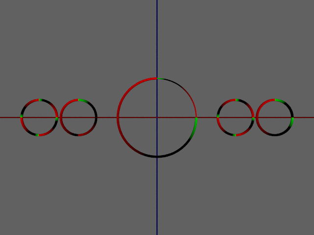
In the attached render, I have the two small tori, with f=360/90=4, and
f=360/270=1.333....
The two on the left are the native radial pattern with no phase adjustment.
The two on the right are my pattern{function{}} versions with the "fixed"
formulas.
The large center circle is two Segment_of_Torus () objects, textured and rotated
into proper position like I wanted.
I think the fact that the two small tori with f=4 look identical, and so this
has been lurking unseen, since I noticed that it can be very hard to pick out if
you don't know it exists, and are using a color map specifically designed to
expose it.
Let me know what you think. org> wrote:
> I started documenting longstanding bugs and issues with VM function and
> pattern interplay. I believe as many as possible should be fixed in the
> POV-Ray v3.8 release. Documenting these bugs/issues as I do my best to
> find and fix them in my personal version of POV-Ray.
Well, I think I found an issue with the way that the angle is calculated for the
radial pattern.
if ((fabs(EPoint[X])<0.001) && (fabs(EPoint[Z])<0.001))
{
value = 0.25;
}
else
{
value = 0.25 + (atan2(EPoint[X],EPoint[Z]) + M_PI) / TWO_M_PI;
}
return(value);
If you plot out the values as you go around the unit circle, there's this weird
90-degree "burp" at the 270 degree mark (Theta = 3pi/4 = 4.712) or x=0, z=-1,
which I think is due to the ... + M_PI) / TWO_M_PI part of the equation.
And you can see it as a distinct discontinuity if you render a torus with a
color map like
#declare CM_GreenRedGradient =
color_map {
[0.0 rgb <0.0, 1.0, 0.0>]
[0.125 rgb <0.0, 0.0, 0.0>]
[0.4 rgb <0.0, 0.0, 0.0>]
[1.0 rgb <1.0, 0.0, 0.0>]
}
and a frequency of 360/270
so that the color and the black show the jump.
This seems to fix it (in my SDL model scene):
#declare Angle = function (XX,ZZ) {atan2 (XX, ZZ)-(pi/2)}
#declare Adjusted = function (XX,ZZ) {select (Angle(XX,ZZ), Angle(XX,ZZ)+tau,
Angle(XX, ZZ))}
#declare FreqPhase = function (XX, ZZ, F, P) {mod ((P*tau+Adjusted (XX, ZZ))*F,
tau)/tau}
It's late and I'm tired, so I'm making more mistakes and so I'm not going to
play around too much more with this tonight. But I do believe this is a real
"bug" in the formula, simply due to the numeric #debug output of the formula and
the sharp discontinuity in the color mapped result.
I believe the expected result should be: the color map starts at 0 (<1, 0>),
works it's way around in the y direction, until it hits frequency F, and then
start at the beginning of the color map: entry [0.0 .....].
From what I can determine with my limited experiments, it does not do this.
In the attached render, I have the two small tori, with f=360/90=4, and
f=360/270=1.333....
The two on the left are the native radial pattern with no phase adjustment.
The two on the right are my pattern{function{}} versions with the "fixed"
formulas.
The large center circle is two Segment_of_Torus () objects, textured and rotated
into proper position like I wanted.
I think the fact that the two small tori with f=4 look identical, and so this
has been lurking unseen, since I noticed that it can be very hard to pick out if
you don't know it exists, and are using a color map specifically designed to
expose it.
Let me know what you think.
Post a reply to this message
Attachments:
Download 'radialrotation.png' (145 KB)
Preview of image 'radialrotation.png'
|
|