|
|
|
|
|
|
| |
| |
|
|
|
|
| |
| |
|
|
I was wanting to work out the SOR segment equations, and found the existing
documentation to be a bit confusing / incomplete.

https://wiki.povray.org/content/Reference:Surface_of_Revolution

The notation is a bit confusing, and there's not enough information to lead me
through the jumps in operations so that I can connect what's going on.

I know there has been some recent effort to improve some of the documentation,
and I think this page would be a good candidate for revision.

If anyone has the knowledge or ability to work out how the curve for each
segment gets interpolated, then a better written explanation and/or SDL
calculating all the points along the entire SOR curve would be great.

Thanks,

- BE
Post a reply to this message
|
|
| |
| |
|
|
|
|
| |
| |
|
|
So where my confusion lies is with the following:

The documentation says,
"The coefficients A(j), B(j), C(j) and D(j) are calculated for every segment
using the equation"
and then immediately gives "b = M * x".


b is a column vector, M is a matrix, and then x is a column vector of the
coefficients that we're supposed to be calculating as implied by that initial
sentence.

The best I have been able to do in terms of trying to work this out and make any
sense of it is:

if b = M * x, and x is the column vector of coefficients, then x = b/M.

So, why start off with how to calculate b, if b is already given in the next
line, and why express it that way if what you actually want to say is that x =
b/M?

The next problem is that M has values that are hard-coded as zeroes, which would
lead to division by zero in every instance, and if a control point leads to any
of the terms of the matrix evaluating to zero, then the same problem occurs.

Finally, it seems that the h's in the b and M calculations are the actual
geometric heights of the control points, whereas the h's in the equation r^2 =
f(h) = A*h^3 + B*h^2 + C*h + D are the values of an interpolant along a single
segment. (otherwise with multiple control points, which of the h's get used? and
which control points get used, if the discussion that immediately follows states
that the function is divided up into separate segments?

Also, I see no "interpolation" happening between point J and point (j+1).

If I am in error, hopefully someone can show me where I missed or misinterpreted
something.

The source code (
https://github.com/POV-Ray/povray/blob/master/source/core/shape/sor.cpp )
states that

*  Ideas for the surface of revolution were taken from:
*
*    P. Burger and D. Gillies, "Rapid Ray Tracing of General Surfaces
*    of Revolution", New Advances in Computer Graphics, Proceedings
*    of CG International '89, R. A. Earnshaw, B. Wyvill (Eds.),
*    Springer, ..., pp. 523-531

and try as I might, I have not been able to find a readable copy of this 1989
paper, nor have had enough time to try and puzzle out the source code to work
backwards.

- BE
Post a reply to this message
|
|
| |
| |
|
|
|
|
| |
| |
|
|
hi,
"Bald Eagle" <cre### [at] netscape net> wrote:
> I was wanting to work out the SOR segment equations, and found the existing
> documentation to be a bit confusing / incomplete.
> https://wiki.povray.org/content/Reference:Surface_of_Revolution
> The notation is a bit confusing, and there's not enough information to lead me
> through the jumps in operations so that I can connect what's going on.
> I know there has been some recent effort to improve some of the documentation,
> and I think this page would be a good candidate for revision.
> If anyone has the knowledge or ability to work out how the curve for each
> segment gets interpolated, then a better written explanation and/or SDL
> calculating all the points along the entire SOR curve would be great.
having just read your follow-up, it seems that the interpolation "loose end"
needs to be sorted. if then you can provide a (working) "worked example" and
(brief ;-)) explanation, we can update that part of the documentation.
regards, jr. net> wrote:
> I was wanting to work out the SOR segment equations, and found the existing
> documentation to be a bit confusing / incomplete.
> https://wiki.povray.org/content/Reference:Surface_of_Revolution
> The notation is a bit confusing, and there's not enough information to lead me
> through the jumps in operations so that I can connect what's going on.
> I know there has been some recent effort to improve some of the documentation,
> and I think this page would be a good candidate for revision.
> If anyone has the knowledge or ability to work out how the curve for each
> segment gets interpolated, then a better written explanation and/or SDL
> calculating all the points along the entire SOR curve would be great.
having just read your follow-up, it seems that the interpolation "loose end"
needs to be sorted. if then you can provide a (working) "worked example" and
(brief ;-)) explanation, we can update that part of the documentation.
regards, jr.
Post a reply to this message
|
|
| |
| |
|
|
|
|
| |
| |
|
|
"jr" <cre### [at] gmailcom> wrote:

> having just read your follow-up, it seems that the interpolation "loose end"
> needs to be sorted.  if then you can provide a (working) "worked example" and
> (brief ;-)) explanation, we can update that part of the documentation.

I'll try to get it worked out, unless someone else manages to do it before me.

I just had some success following up on a hunch that the spline is a Catmull-Rom
type.

https://qroph.github.io/2018/07/30/smooth-paths-using-catmull-rom-splines.html

https://www.cs.cmu.edu/~fp/courses/graphics/asst5/catmullRom.pdf

https://andrewhungblog.wordpress.com/2017/03/03/catmull-rom-splines-in-plain-english/

-BW
Post a reply to this message
|
|
| |
| |
|
|
|
|
| |
| |
|
|
"Bald Eagle" <cre### [at] netscapenet> wrote:

>
https://andrewhungblog.wordpress.com/2017/03/03/catmull-rom-splines-in-plain-english/

This last one seemed to be pretty straightforward to follow, and I managed to
implement it in Excel.

So hopefully I'll be able to get the SDL to work tonight.

- BW
Post a reply to this message
|
|
| |
| |
|
|
|
|
| |
| |
|
|
I suppose that my next logical question is:

the sor documentation states, "The intersection test with a SOR object involves
solving a cubic polynomial while the test with a lathe object requires to solve
a 6th order polynomial" ...

but upon reviewing the lathe documentation, one can choose between a variety of
different spline types.

So perhaps that needs some clarification / correction / expansion.

(I've also written a Newton-Raphson root solver, and so probably should
investigate the Sturmian root solver.)

- BW
Post a reply to this message
|
|
| |
| |
|
|
|
|
| |
| |
|
|
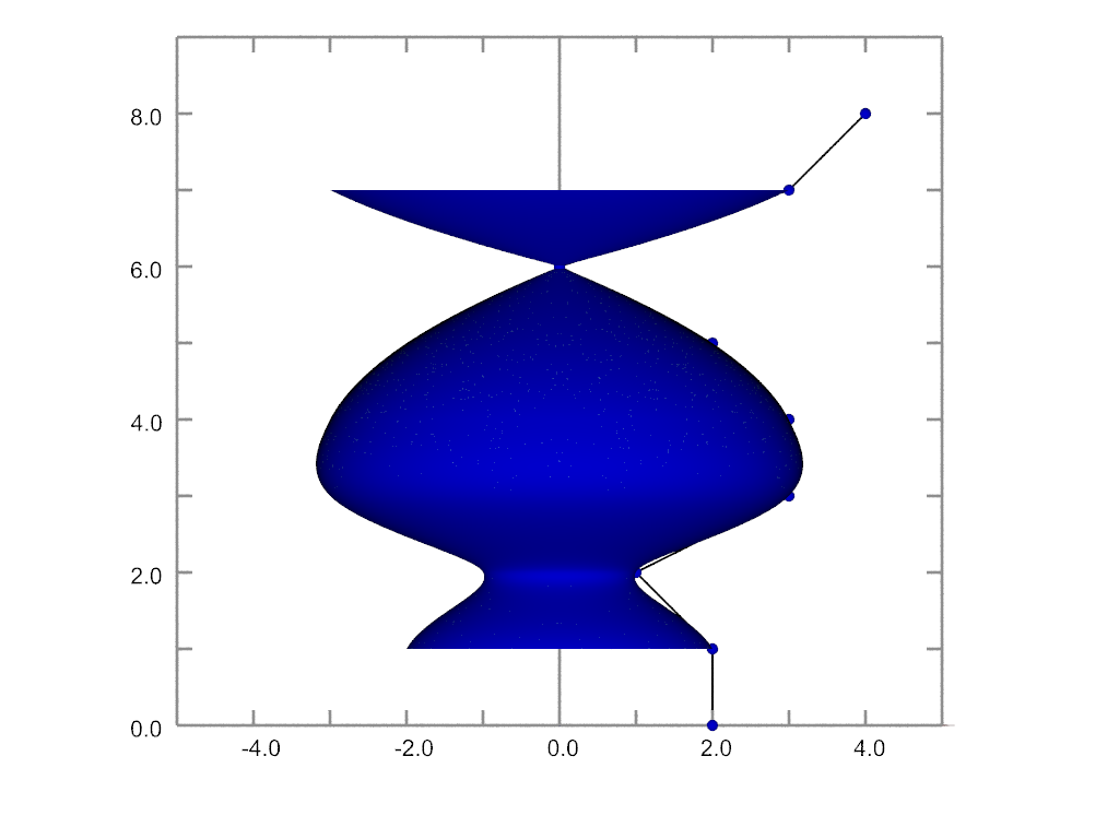
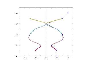
"Bald Eagle" <cre### [at] netscapenet> wrote:

> So hopefully I'll be able to get the SDL to work tonight.

It took longer than i thought, because in order to make the f(h) equation match
the documentation, I had to flip everything upside down and backwards from the
way I did it in Excel.  And I used arrays.

But it all works, which is what I needed to do.

With regard to POV 4.0, I see no reason why the number of points needs to be
specified, since the source can count the points when parsing the SDL.
There ought to be a way to specify the "tension" like in a proper Catmull-Rom
spline.

Anyway, here ya go.

- BW
Post a reply to this message
Attachments:
Download 'surface of revolution documentation.png' (62 KB)
Preview of image 'surface of revolution documentation.png'
|
|
| |
| |
|
|
|
|
| |
| |
|
|
"jr" <cre### [at] gmailcom> wrote:

> having just read your follow-up, it seems that the interpolation "loose end"
> needs to be sorted.

So, I just wrote the whole thing from scratch, the way it seemed to me to work,
according to that last linked Wordpress page.

https://wiki.povray.org/content/File:RefImgCurvmath.png
Looks like it was made, or at least uploaded by Jim Holsenback.

> if then you can provide a (working) "worked example" and
> (brief ;-)) explanation, we can update that part of the documentation.

I can likely provide a "mathematical" or a code example - either as the vector *
matrix form, or as the intermediate result (A, B, C, & D).

There are some YT videos that seem to go over the topic, so perhaps I can either
use on of those, or dig up the original paper by Catmull and Rom to show the
derivation, and why the vector and matrix values are what they are.

In typical fashion, I can expand all that to simulate / demonstrate how that
curve gets wrapped around the axis to make the "sor" object (both
graphically/geometrically and mathematically), as well as render it as a
parametric {} and an isosurface {}.  Easy enough to do that as a union of
triangle{}s, perhaps mesh {}, less likely mesh2{}.

I already edited the doc page in OpenOffice as a first rough draft, however it
may need revision after I at some point figure out exactly what's going on with
the lathe {} object.

As with all things, I'd like to see some level of clarity, completeness, and
comprehensiveness in our documentation.  So, in my mind, I would like to see
POV-Ray serve as a repository of computer graphics education that clearly and
completely explains all of the historical and current concepts in computer
graphics, with references, working code, and of course eye-popping artistic
renders.
So perhaps we can make a list of all of the various different kinds of splines,
and see if we can't get as many of them implemented as is practical.  I know
Jerome worked out Rational Bezier Splines a while back, and TOK has NURBS worked
out.  Even though none of it is in source, it can be implemented via
macros/include files, and in a way, that's a better educational resource that
people can refer to.

* Because we need to attract more people here to spur further development *

- BW

P. S.

With regard to the "equations as images" that we have in ours docs, I'd like to
see some level of plain text version that can be copy/pasted.  Or if there is
some way, perhaps we can have MathJax implemented so that we can have great
looking equations.
Post a reply to this message
|
|
| |
| |
|
|
|
|
| |
| |
|
|
This covers the basics,

https://www.cs.cmu.edu/~fp/courses/graphics/asst5/catmullRom.pdf

but Wikipedia shows that there are uniform, chordal, and centripetal forms as
well.

(granted for our present purposes, I think we are just using the uniform version
with a tension of 1.0 )
Post a reply to this message
|
|
| |
| |
|
|
|
|
| |
| |
|
|
hi,

"Bald Eagle" <cre### [at] netscapenet> wrote:
> "jr" <cre### [at] gmailcom> wrote:
> ...
> With regard to the "equations as images" that we have in ours docs, I'd like to
> see some level of plain text version that can be copy/pasted.  Or if there is
> some way, perhaps we can have MathJax implemented so that we can have great
> looking equations.

I'll reply tomorrow (Sunday), via email, on topic.  on the above, the wiki has a
math extension installed, perhaps that should enable you to write the equations
"in text" (see attached).


regards, jr.
Post a reply to this message
Attachments:
Download 'screenshot 2025-08-16 07.02.03.png' (34 KB)
Preview of image 'screenshot 2025-08-16 07.02.03.png'

|
|
| |
| |
|
|
|
|
| |
| |
|
|
"jr" <cre### [at] gmailcom> wrote:

> I'll reply tomorrow (Sunday), via email, on topic.

Well, before I go changing the documentation for POV-Ray,  I'd like to point out
that currently I have only worked out some form of the Catmull-Rom spline that
seems to work in a predictable way.

I'm currently at the state where I'm looking at the source code in sor.cpp to
try and figure out if the 2 things match in some way.

https://github.com/POV-Ray/povray/blob/master/source/core/shape/sor.cpp

1. The source uses the x and y values of the control points separately in the
terms of the equations used to solve for the coefficients.  I do not.

2. The source uses powers of the control point y values in the matrix, whereas I
do not.

3. The source performs a matrix inversion before calculating the coefficients.
No idea why, or what that does (yet).

4. Then there are other adjustments after that,
c[0] = 3.0 * A;
c[1] = 2.0 * B;
c[2] = C;


5. and then they somehow need to "solve a polynomial" - presumably to find a
root.
        n = Solve_Polynomial(2, c, r, false, 0.0, stats);

6. then this n value is used as the iterator in the interpolation
while (n--)
        {
            if ((r[n] >= y[0]) && (r[n] <= y[1]))
            {
                x[n] = sqrt(r[n] * (r[n] * (r[n] * A + B) + C) + D);
            }
        }


Which all seems bewilderingly complex to me, but seems to jive with current
documentation.
HOW that all works is currently beyond me.
It's just a giant big black box.

Somewhere around 2000, it seemed to be beyond Warp as well.

I have some thing to do today and tomorrow, but Maybe I can spin my version
around the y-axis and compare it the actual sor object and see if they're even
close.

- BW
Post a reply to this message
|
|
| |
| |
|
|
|
|
| |
| |
|
|
At the moment, everything is looking to more or less ok, there probably only
needs to be a minor amount of clarification and explanation to make the
documentation sufficiently user-friendly.

I added some comments to the source code for sor.cpp
and hopefully I can make a little more progress on comparing my own version
written from scratch to what's going on in source.

There are normal, chordal, and centripetal forms.
I suspect mine is the normal form, and the one in source is centripetal.

(I will need to check source against the following, which I stumbled upon)

https://splines.readthedocs.io/en/latest/euclidean/catmull-rom-properties.html

So the first thing we need to do is set up our system of equations that relates
a cubic interpolation between the START (P1) and END (P2) points of the spline
to the constraints for the data, namely that the spline has to pass _through_
the endpoints, and the tangents at the endpoints for the spline segments are
defined using the additional spline points P0 and P3.

Following along with the comments that summarize the matrix values, it will be
fairly easy to match this up with what is going on in this video:
https://www.youtube.com/watch?v=DLsqkWV6Cag

 /* Use cubic interpolation. */

        k[0] = P[i+1][X] * P[i+1][X];       // P1.x^2, actual spline start
        k[1] = P[i+2][X] * P[i+2][X];       // P2.x^2, actual spline end
        k[2] = (P[i+2][X] - P[i][X]) / (P[i+2][Y] - P[i][Y]);    // df/dt at
spline start
        k[3] = (P[i+3][X] - P[i+1][X]) / (P[i+3][Y] - P[i+1][Y]);   // df/dt at
spline end (tangent)

        k[2] *= 2.0 * P[i+1][X];       // = 2 P1.x * (P2.x - P0.x)
                ----------------------
                  (P2.y - P0.y)

        k[3] *= 2.0 * P[i+2][X];       // = 2 P2.x * (P3.x - P1.x)
                ----------------------
                  (P3.y - P1.y)

        w = P[i+1][Y];

        Mat[0][0] = w * w * w;        // P1.y^3
        Mat[0][1] = w * w;        // P1.y^2
        Mat[0][2] = w;         // P1.y
        Mat[0][3] = 1.0;        // 1

        Mat[2][0] = 3.0 * w * w;       // 3*P1.y^2
        Mat[2][1] = 2.0 * w;        // 2*P1.y
        Mat[2][2] = 1.0;        // 1
        Mat[2][3] = 0.0;        // 0

        w = P[i+2][Y];

        Mat[1][0] = w * w * w;        // P2.y^3
        Mat[1][1] = w * w;        // P2.y^2
        Mat[1][2] = w;         // P2.y
        Mat[1][3] = 1.0;        // 1

        Mat[3][0] = 3.0 * w * w;       // 3*P2.y^2
        Mat[3][1] = 2.0 * w;        // 2*P2.y
        Mat[3][2] = 1.0;        // 1
        Mat[3][3] = 0.0;        // 0


-------------------------------------------------------------------------
One can solve a system of linear equations in a matrix using a number of
different methods.
The source uses the method of finding the matrix inverse, and then multiplying
both sides of the matrix equation by the matrix inverse.
(This is where the over-brief equation in the docs is confusing, without any
other context)

-------------------------------------------------------------------------


 // Now we find the matrix inverse so that we can solve for the coefficients
 /*
       ax = b
 (1/a)*ax = (1/a)*b
 (a^-1)ax = (a^-1)b
 (a^-1)*x = 1, so
        x = (a^-1) b
 */

        MInvers(Mat, Mat);        // in math/matrix.cpp

 // Once we have the matrix inverse, we take the data constraints and the matrix
inverse and
 // multiply them to calculate the coefficients.

        /* Calculate coefficients of cubic patch. */
 // k[] is the column vector of the constraints
 // and Mat[] is the *matrix_inverse* M
 // so multiplying together equals the column vector of the coefficients

        A = k[0] * Mat[0][0] + k[1] * Mat[0][1] + k[2] * Mat[0][2] + k[3] *
Mat[0][3];
        B = k[0] * Mat[1][0] + k[1] * Mat[1][1] + k[2] * Mat[1][2] + k[3] *
Mat[1][3];
        C = k[0] * Mat[2][0] + k[1] * Mat[2][1] + k[2] * Mat[2][2] + k[3] *
Mat[2][3];
        D = k[0] * Mat[3][0] + k[1] * Mat[3][1] + k[2] * Mat[3][2] + k[3] *
Mat[3][3];


I still feel like there should be some minus signs in there to make the
interpolation work - but maybe those pop out the other side of the MInvers () .
.. . I'll have to write that out in SDL and run it to find out.

I also don't quite understand why we need to take the square root of the result
in line 1082
x[n] = sqrt(r[n] * (r[n] * (r[n] * A + B) + C) + D);
to get the interpolated spline values, but perhaps that may become clear as I
find more bits of time here and the to properly focus on this.

Just wanted to issue a progress report.   :)

- BE
Post a reply to this message
|
|
| |
| |
|
|
|
|
| |
| |
|
|
"Bald Eagle" <cre### [at] netscapenet> wrote:

> I still feel like there should be some minus signs in there to make the
> interpolation work - but maybe those pop out the other side of the MInvers () .
> .. . I'll have to write that out in SDL and run it to find out.

Sent values of A-D for each segment to the debug stream, and there are
definitely minus signs.

> I also don't quite understand why we need to take the square root of the result
> in line 1082
> x[n] = sqrt(r[n] * (r[n] * (r[n] * A + B) + C) + D);
> to get the interpolated spline values, but perhaps that may become clear as I
> find more bits of time here and the to properly focus on this.

This apparently has to do with the value of "alpha" in the interpolation, with 0
being Uniform, 1/2 being Centripetal, and 1 being Chordal.
I'm not really sure where "r" comes from in the source, or how that while loop
interpolates the spline, but I just ignored all of that, and things worked out
anyway.  :D

After fixing some boneheaded visualization bugs, the math seemed to be working
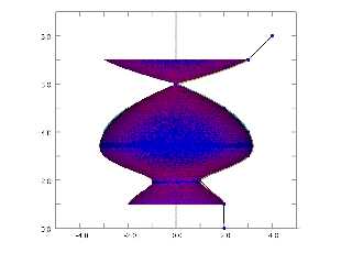
out with the spline, so I took my SDL version of the SOR spline and used the X
value (minus the minor radius) as the major radius of a torus, and "plotted" a
torus at each interpolation point. (RED)

Seems to overlay the sor {} object (BLUE) very closely.  Errors are probably due
to my janky simulation method, and coincident surfaces.

I'll try to work out the details as I write things up, and I'll probably make a
parametric {} and isosurface {} object to further test how well things match up.

- BE
Post a reply to this message
Attachments:
Download 'surface of revolution documentation.png' (255 KB)
Preview of image 'surface of revolution documentation.png'
|
|
| |
| |
|
|
|
|
| |
| |
|
|
"Bald Eagle" <cre### [at] netscapenet> wrote:

> ... I'll probably make a
> parametric {} and isosurface {} object to further test how well things match up.

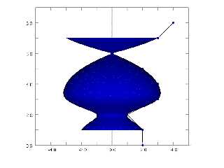
So this is the isosurface version, overlaid on the POV-Ray sor {} object

object {SOR scale 0.999999}

(It's actually one isosurface for every individual segment of the CR spline)

If I scale to 5 nines, I get a LOT more coincident surface artefacts, so I'd say
that everything is working very nicely.

I would still like to see that original 1989 paper, and perhaps I can work out
the square root thing with some level of rigor.

I'm pretty happy with what I've got, and will get working on some sort of
write-up.

If anyone has any questions, or would like to see a specific type of render,
animation, or mathematical derivation, just let me know, so I can include that.

- BE
Post a reply to this message
Attachments:
Download 'surface of revolution documentation.png' (80 KB)
Preview of image 'surface of revolution documentation.png'
|
|
| |
| |
|
|
|
|
| |
| |
|
|
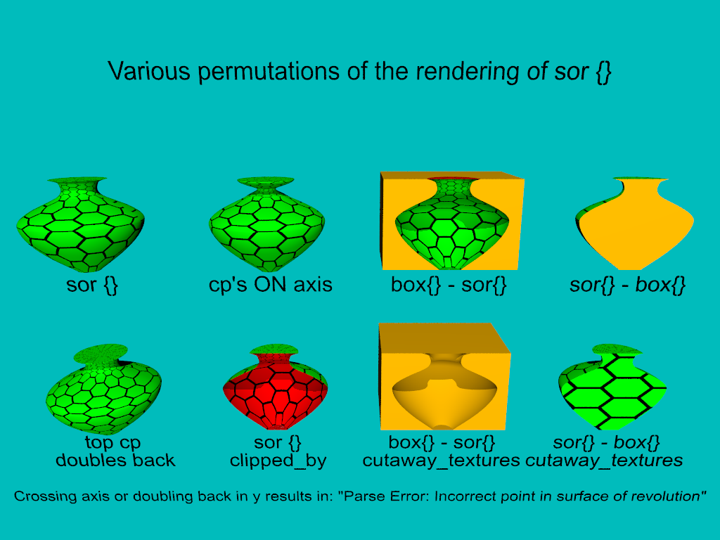
So, in the course of making some documentation renders, it became apparent that
there were a few things that were puzzling, needed to be sorted out, and some of
that was related to the behaviour of other keywords.

The following is a summary:

sor {} can have control points ON the axis, just not crossing it.
Else you get a "Parse Error: Incorrect point in surface of revolution"
I believe this is hard-coded behaviour in the source algorithm.
If I were to edit the source, it would allow the first and last control points
to cross the axis, since those points only exist to calculate the tangent
direction.

I do recall discussing this briefly in a thread with clipka and suggesting to
use abs {} somewhere in the algorithm, but I'd have to familiarize myself more
deeply with the specifics of what is going on numerically.

When using the sor {] object as the "cutter" in a difference {}, I unexpectedly
got some interior_texture {} showing in the result. Strangely enough, when i use
sor {open} the interior_texture {} is NOT visible, and I only see the surface
texture {}

When cutting away from the sor {}, I see the expected result, though I haven't
pursued this to see what more complicated geometry / CSG yields.

According to the sor {} tutorial in the wiki:
https://wiki.povray.org/content/Documentation:Tutorial_Section_3#Surface_of_Revolution_Object
"First and last point from the list are used to determine slope at beginning and
end of curve and can be defined for any height."

However, I find that to not be the case.
Swapping the first and last control points causes a
"Parse Error: Incorrect point in surface of revolution"
But if I only set the LAST control point y value to zero, technically making the
spline double-back in the y-direction, everything works fine.

and finally on to what sparked this whole investigation off:
I wanted to make a render comparing sor{} with sor {open}, but I had a devil of
a time slicing the vase in half and seeing the interior.

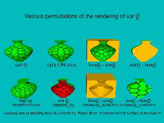
jr managed to achieve the desired result using clipped_by

As shown, when I use cutaway_textures, I DON'T see the expected
interior_texture, but the surface texture {}.  And when I use sor {open}, I do
not see a hollow infinitely thin surface, I get a solid object sliced in half.

So, I would say that there are problems with the sor {} caps, possibly with the
normal vector.

As shown in the bottom left, when I slice the sor {open} in half with a box, I
get an apparently solid object.  This is of course counterintuitive to what the
user expects, even though the documentation cautions that the open version might
yield unexpected results when used in CSG.  I would probably classify this
result as sufficiently unexpected as to warrant its classification as a bug, or
for an extended warning with the clipped_by solution to be added to the
documentation.

Futhermore, if the documentation implies that a sor is solid - just look at the
CSG results of difference {} - then clipped_by ought to give me what I'm seeing
as difference {} only with the interior_texture {} properly displayed.


Other things I notice are that there is some noisy "cruft" at the base of the
clipped_by object.  I also see some of that at the bottom of the difference{}s.

The texture is a tiling with a color_map, and is uv_mapped onto the surface(s).
As you can see on the right side of the object, the pattern does not line up
properly at the edges.  In the model below that, "top cp doubles back", I
changed the scaling of the tiling to an even number, and it now lines up.

I recall reading about properly scaling patterns so that make them fit, and that
of course employed the use of pi or tau to calculate the proper scaling.  This
might be a worthwhile keyword to implement for uv-mapping, perhaps some sort of
"scaling warp".  Likely to be pattern and direction dependent.

All objects are rendered with sturm.

Enjoy & Discuss.

- BE
Post a reply to this message
Attachments:
Download 'sor permutations.png' (130 KB)
Preview of image 'sor permutations.png'
|
|
| |
| |
|
|
|
|
| |
| |
|
|
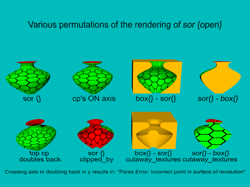
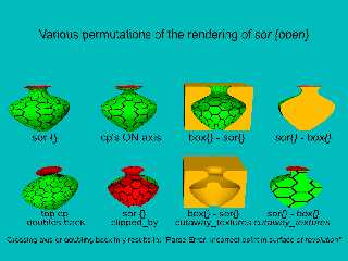
Same renderings, but of sor {open}
Post a reply to this message
Attachments:
Download 'sor open permutations.png' (133 KB)
Preview of image 'sor open permutations.png'
|
|
| |
| |
|
|
|
|
| |
| |
|
|
"Bald Eagle" <cre### [at] netscapenet> wrote:

> As shown, when I use cutaway_textures, I DON'T see the expected
> interior_texture, but the surface texture {}.  And when I use sor {open}, I do
> not see a hollow infinitely thin surface, I get a solid object sliced in half.

Also, I'm curious as to why the cutaway_textures feature requires the use of an
untextured object as a cutter to be able to function properly.
One would reasonably expect that we should be able to use any object.
If, as per wiki documentation, the cutaway_textures feature result is based on
insidedness tests, then the texture of the cutter should be irrelevant.

- BE
Post a reply to this message
|
|
| |
| |
|
|
|
|
| |
| |
|
|
On 9/7/25 12:10, Bald Eagle wrote:
> According to the sor {} tutorial in the wiki:
> https://wiki.povray.org/content/
> Documentation:Tutorial_Section_3#Surface_of_Revolution_Object
> "First and last point from the list are used to determine slope at beginning and
> end of curve and can be defined for any height."
>
> However, I find that to not be the case.
> Swapping the first and last control points causes a
> "Parse Error: Incorrect point in surface of revolution"
> But if I only set the LAST control point y value to zero, technically making the
> spline double-back in the y-direction, everything works fine.

First, Are you using v3.8 beta 2 for all your testing?

Second, Did you take care when you did the differences with the box to
not have coincident surfaces with the caps (if there) or that y height
when the caps are not there?

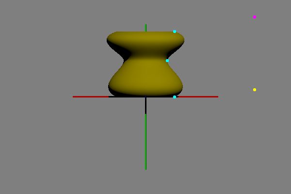
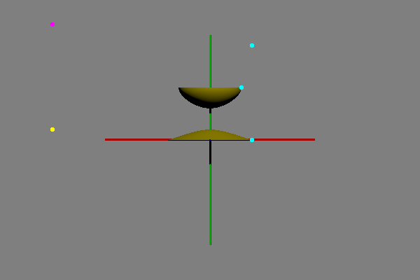
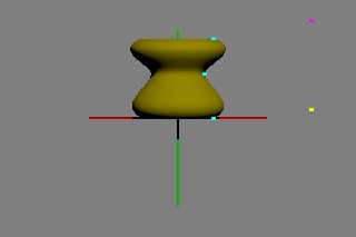
As to the point above, I don't see what you see. The following list
works for me where I have flipped / crossed the first and last control
points(*). See the attached image where the first is magenta and the
last is yellow.

     <+1.5,+1.1> // C0
     <+0.4,0.0>  // C1
     <+0.3,0.5>  // C2
     <+0.4,0.9>  // C3
     <+1.5,+0.1> // C4

I'll try and look at some of the other issues you mention as I have
time; Including temporarily removing the x>0.0 restriction on the first
and last points to see what happens. Aside: we did remove a similar
restriction for the lathe for v3.8 vs v3.7.

(*) I tried inverting all the on curve points and this does NOT work as
I incorrectly remembered for some recent sor{} post - that must be a
lathe{} only thing.

Bill P.
Post a reply to this message
Attachments:
Download 'be_sor01.png' (12 KB)
Preview of image 'be_sor01.png'
|
|
| |
| |
|
|
|
|
| |
| |
|
|
On 9/8/25 07:08, Bald Eagle wrote:
> "Bald Eagle" <cre### [at] netscapenet> wrote:
>
>> As shown, when I use cutaway_textures, I DON'T see the expected
>> interior_texture, but the surface texture {}.  And when I use sor {open}, I do
>> not see a hollow infinitely thin surface, I get a solid object sliced in half.
>
> Also, I'm curious as to why the cutaway_textures feature requires the use of an
> untextured object as a cutter to be able to function properly.
> One would reasonably expect that we should be able to use any object.
> If, as per wiki documentation, the cutaway_textures feature result is based on
> insidedness tests, then the texture of the cutter should be irrelevant.
>
> - BE
>
>
>

Answering without thinking much, I don't think the cutaway_textures
feature copies the inside texture(*), but maybe I'm not remembering
correctly.

A reminder the yuqk fork fixed a cutaway_textures bug which exists in
official POV-Ray releases. See:

https://news.povray.org/povray.bugreports/thread/%3C65806257%241%40news.povray.org%3E/

Bill P.


(*) - The inside_texture{}s feature has a few inconsistencies, besides,
with respect to how texture{}s are handled.
Post a reply to this message
|
|
| |
| |
|
|
|
|
| |
| |
|
|
On 9/8/25 10:04, William F Pokorny wrote:
> Answering without thinking much,

Ah, and to quote Alain:

"When using cutaway_texture, the object used to cut away part of the
rest must NOT have any texture."

Unsure your set up with respect to the particular post, but the overall
images suggest both the box and sor might have textures ?

Bill P.
Post a reply to this message
|
|
| |
| |
|
|
|
|
| |
| |
|
|
On 9/8/25 09:52, William F Pokorny wrote:
> I'll try and look at some of the other issues you mention as I have
> time; Including temporarily removing the x>0.0 restriction on the first
> and last points to see what happens. Aside: we did remove a similar
> restriction for the lathe for v3.8 vs v3.7.

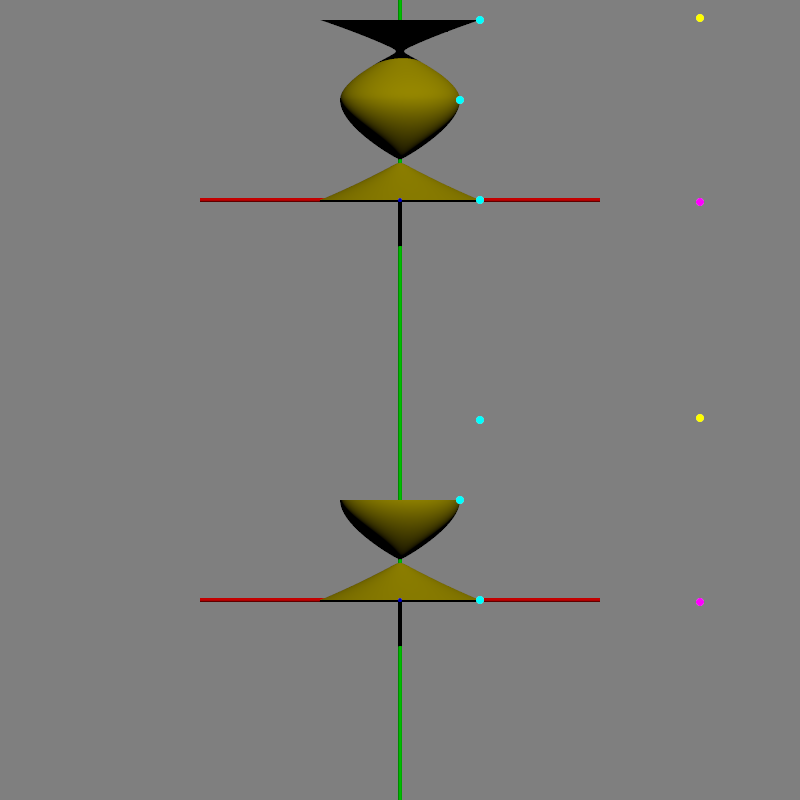
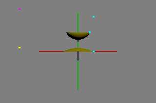
Well, the current code drops portions of the curve that get pulled into
x<0 territory by control points x<0. See attached image.

Might be fixable / map-able to x>=0 as you, I think, were suggesting
with the abs() comment. It might even acceptable as a final result, IF,
the inside tests, normal calculations and uv mapping code map in a sane
way to the result.

Thinking aloud, it might be possible to allow x<0 control points - ONLY
- where both on curve points and off curve control points are forced to
be always ascending (>= previous) in y. This, probably, would cover the
'useful' x<0 control point cases while preventing the curve from
crossing into -x?  I'll try to play with this thought some more when I
again have time - need to run.

Bill P.
Post a reply to this message
Attachments:
Download 'be_sor02.png' (5 KB)
Preview of image 'be_sor02.png'
|
|
| |
| |
|
|
|
|
| |
| |
|
|
William F Pokorny <ano### [at] anonymousorg> wrote:

> First, Are you using v3.8 beta 2 for all your testing?
Probably.  Will confirm when I get home.

> Second, Did you take care when you did the differences with the box to
> not have coincident surfaces with the caps (if there) or that y height
> when the caps are not there?

Yeah, I have an E value set that I routinely use to avoid CS.
I had the caps present when I skipped adding/subtracting that, and then when I
fixed it, the caps went away.


> (*) I tried inverting all the on curve points and this does NOT work as
> I incorrectly remembered for some recent sor{} post - that must be a
> lathe{} only thing.

Right, because sor is an implicit interpolation, and lathe is a parametric
interpolation.

Thanks for checking on these.  Will compare notes when I get back later.

- BW
Post a reply to this message
|
|
| |
| |
|
|
|
|
| |
| |
|
|
William F Pokorny <ano### [at] anonymousorg> wrote:

> Ah, and to quote Alain:
>
> "When using cutaway_texture, the object used to cut away part of the
> rest must NOT have any texture."
>
> Unsure your set up with respect to the particular post, but the overall
> images suggest both the box and sor might have textures ?

I initially did leave the textures attached to the objects when first doing the
differences, but my code is such that it was easy to leave them textureless for
use with cutaway_textures, so no, that doesn't appear to be the problem.

Will post the scene file when I get out of here in an hour.

With regard to c_t not using interior_texture, that seems to be a reasonably
expected behaviour, and one which I'd have to think hard about how to code a
workaround for.

I also had that recent scene where I was getting washed-out colors, and I really
don't believe that I have any overlapping objects, however I will have to make a
detailed check to be absolutely sure.

- BW
Post a reply to this message
|
|
| |
| |
|
|
|
|
| |
| |
|
|
"Bald Eagle" <cre### [at] netscapenet> wrote:

using
3.8.0-beta.2+gh7.msvc14.win64


scene file attached
Post a reply to this message
Attachments:
Download 'sor permutations.pov.txt' (6 KB)
|
|
| |
| |
|
|
|
|
| |
| |
|
|
On 9/8/25 11:10, William F Pokorny wrote:
> Thinking aloud, it might be possible to allow x<0 control points - ONLY
> - where both on curve points and off curve control points are forced to
> be always ascending (>= previous) in y. This, probably, would cover the
> 'useful' x<0 control point cases while preventing the curve from
> crossing into -x?  I'll try to play with this thought some more when I
> again have time - need to run.

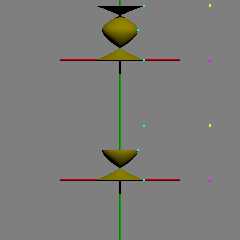
I spent some time on this idea and, on seeing some issues where entire
segments would just blink out of existence, I went back to trying more
parser legal point sets and found similar weirdness. :-(

There exists internal cylinder bounding of segments intended to reduce
the number of calls to the solvers. My guess is that code isn't
completely solid, but who knows.

Attached an image where the top row uses the currently legal point set of:

     <+1.5,-0.01> // C0
     <+0.4, 0.0>  // P1
     <+0.3, 0.5>  // P2
     <+0.4, 0.9>  // P3
     <+1.5,+0.91> // C4

and the shape breaks apart(a)(b). In the bottom row I changed that last
control point to:

    <+1.5,+0.901> // C4

and the entire top segment drops out.

So yep...

Bill P.

(a) Curve going negative can already happen without negative control
points.

(b) In yuqk the parts of the sor there all look good. In v3.8 beta 2,
the results for top segment are noisy; Likely solver differences.
Post a reply to this message
Attachments:
Download 'sor_oddness.png' (22 KB)
Preview of image 'sor_oddness.png'
|
|
| |
| |
|
|
|
|
| |
| |
|
|
On 9/8/25 14:06, Bald Eagle wrote:
>> (*) I tried inverting all the on curve points and this does NOT work as
>> I incorrectly remembered for some recent sor{} post - that must be a
>> lathe{} only thing.
...> Right, because sor is an implicit interpolation, and lathe is a
parametric
> interpolation.

Unsure. With the lathe the reason to flip the point set order is to flip
the normals (and perhaps too textures on parts of the resulting shape). Ref:

https://news.povray.org/povray.binaries.images/thread/%3C5745b756%241@news.povray.org%3E/

I see no reason this couldn't be true for the sor too - even if all that
happens internally is normalizing the decreasing point during parsing
and setting a flag to flip the normals.

That said. When I relaxed the parser's sanity checking so I could try
and render the reversed point set I got no sor result. Given other
discoveries this morning this might also be related to segments simply
dropping out due how the internal cylinder bounding is being done. I
don't know. I don't know. I don't know.

Bill P.
Post a reply to this message
|
|
| |
| |
|
|
|
|
| |
| |
|
|
William F Pokorny <ano### [at] anonymousorg> wrote:
> On 9/8/25 14:06, Bald Eagle wrote:
> >> (*) I tried inverting all the on curve points and this does NOT work as
> >> I incorrectly remembered for some recent sor{} post - that must be a
> >> lathe{} only thing.
> ...> Right, because sor is an implicit interpolation, and lathe is a
> parametric
> > interpolation.
>
> Unsure. With the lathe the reason to flip the point set order is to flip
> the normals (and perhaps too textures on parts of the resulting shape). Ref:
>
>
https://news.povray.org/povray.binaries.images/thread/%3C5745b756%241@news.povray.org%3E/

Yes, but this is not what I'm talking about.
I'm not trying to reverse the order of the entire point set, (which _ought_ to
be a valid point set for the sor - I think it's just "lazily" coded to check in
one direction - I think it could easily check for points going sequentially in
either direction)  I'm just trying to use ANY value for either the first or last
control point to change the tangent direction at the endpoints.

> I see no reason this couldn't be true for the sor too - even if all that
> happens internally is normalizing the decreasing point during parsing
> and setting a flag to flip the normals.

Yes, but even if we still just had the current sor monotonically increasing in
y, we could just switch texture and interior_texture to achieve the same result.
But I agree that given your point, sor could really use a much more in-depth
investigation and possible/probable recoding.

With regard to the abs() implementation, that was only to be applied to the r
result of the sor, so that anything that crossed the rotation axis would be a
valid control point.  I just didn't see why a mirror-image control point would
be invalid.

> That said. When I relaxed the parser's sanity checking so I could try
> and render the reversed point set I got no sor result. Given other
> discoveries this morning this might also be related to segments simply
> dropping out due how the internal cylinder bounding is being done.

I skimmed over the internal bounding part, but can try to devote some more time
to verifying what it does and how.

One thing that I noticed with going over the source code several different
objects is that we have a repetition of spline code - why don't we have all the
splines in one place and use them as the basis for all the various objects that
use them?

Simplifying things like that would make sure that the splines are consistent
between the various objects, and potentially open up the ability to use
user-defined spline interpolations for defining the outline of the objects.

- BW
Post a reply to this message
|
|
| |
| |
|
|
|
|
| |
| |
|
|
William F Pokorny <ano### [at] anonymousorg> wrote:

>      <+1.5,+0.91> // C4
>
> and the shape breaks apart(a)(b). In the bottom row I changed that last
> control point to:
>
>     <+1.5,+0.901> // C4
>
> and the entire top segment drops out.

Looking at the code, I'd say that either it's the solver or the EPSILON value -
or both.  That's definitely a weird result, and you have an excellent sense for
employing good incidental test cases.
I'd say that this is the kind of thing where more extensive diagramming of the
actual control points and cubic spline would be helpful, and maybe have a grid
of sor {} objects with varying control points.

I have a bit of trouble putting all of the pieces in sor.cpp together to see how
all of the data flows in order to make the actual sor on-screen.  If you could
explain that briefly, that would be a huge help in my ongoing investigations and
debugging.

Do you see anywhere that the code would simply not render the surface?  Any way
to indicate to the user that it does such a thing?

> (b) In yuqk the parts of the sor there all look good. In v3.8 beta 2,
> the results for top segment are noisy; Likely solver differences.

In the source:
Where is "Number" defined?
Where is EPSILON defined?

Some things I've noticed and am confused by:

In void Sor::Compute_Sor(Vector2d *P, RenderStatistics& stats) [Line 960]

starting at line 1003, we have:
    for (i = 0; i < Number; i++)
    {
        if ((fabs(P[i+2][Y] - P[i][Y]) < EPSILON) ||
            (fabs(P[i+3][Y] - P[i+1][Y]) < EPSILON))
        {
            throw POV_EXCEPTION_STRING("Incorrect point in surface of
revolution.");
        }

which is the only check that throws that error, and because it uses fabs (),
that doesn't actually check for the control points doubling back on themselves,
it seems like that's a check to make sure the tangent doesn't have a slope of
zero.

Now, moving down to line 1078, we have:
        while (n--)
        {
            if ((r[n] >= y[0]) && (r[n] <= y[1]))
            {
                x[n] = sqrt(r[n] * (r[n] * (r[n] * A + B) + C) + D);
            }
        }

and I'm confused as to why r is getting compared to the y value and not the x
value.  It seems that the radius ought to be compared to the control point x
values - unless I'm missing something.

Also, as far as I'm aware, the Catmull-Rom spline doesn't have as well-defined a
control polygon as a Bezier spline does, and so I'm wondering if there needs to
be a better bounding estimate for the min and max values.

So something that's been bouncing around the ole' noggin but I haven't yet
articulated is:
If we interpolate a spline with entirely valid control points, but the
interpolated part winds up crossing the rotation axis - what happens?
Post a reply to this message
|
|
| |
| |
|
|
|
|
| |
| |
|
|
"Bald Eagle" <cre### [at] netscapenet> wrote:

> Now, moving down to line 1078, we have:
>         while (n--)
>         {
>             if ((r[n] >= y[0]) && (r[n] <= y[1]))
>             {
>                 x[n] = sqrt(r[n] * (r[n] * (r[n] * A + B) + C) + D);
>             }
>         }
>
> and I'm confused as to why r is getting compared to the y value and not the x
> value.  It seems that the radius ought to be compared to the control point x
> values - unless I'm missing something.

This is because good ole' Dieter likes to mix and match labels between the
comments and the code.
r here is the array of roots found by the polynomial solver, not the radius of
the sor at that height (which is x).  So we're just checking to make sure we're
testing between the roots.  Still need to see why the roots bracket a spline
segment . . .

- BW
Post a reply to this message
|
|
| |
| |
|
|
|
|
| |
| |
|
|
William F Pokorny <ano### [at] anonymousorg> wrote:
.... how the internal cylinder bounding is being done. I

Check out Fig. 5, pg 11
https://www.cemyuksel.com/research/catmullrom_param/catmullrom_cad.pdf

We might have better luck if we changed how the bounding is done.
It also shows how I can create a set of control points where the curve
overshoots the control point polygon, and so I can use that to have the
interpolated curve cross over the rotation axis to see what happens.

I'll make a speculative prediction and say that the algorithm will try to take
the sqrt of that negative radius and fail - either throwing an error, or just
blanking out that portion of the curve - or the whole segment.

I'll probably have to convert most of the solver code to SDL and then use what I
get out of that to start to answer some other questions.

- BW
Post a reply to this message
|
|
| |
| |
|
|
|
|
| |
| |
|
|
On 9/10/25 09:27, Bald Eagle wrote:
> I'll make a speculative prediction and say that the algorithm will try to take
> the sqrt of that negative radius and fail - either throwing an error, or just
> blanking out that portion of the curve - or the whole segment.

Thanks for reference! :-)

If you're referring to the sqrt I think you are, you've guessed
correctly! :-) I have a potential fix for it. The sqrt(-) along with
some fine detail in how std::min(), std::max() work when passed a -nan
value as the first argument vs the second argument cause the segment
blink out issue. Only limited testing thus far. Maybe I'll get to more
tonight.

I see some other not really wrong, but not optimal stuff happening too
with the cylinder segment bounding in y. Sort of as if it was written to
support on curve points in ascending or descending order less any
optimization for the y coordinates (The cylinders get taller and taller
as you have more segments instead of aligning with each of the segments
in y).

Bill P.
Post a reply to this message
|
|
| |
| |
|
|
|
|
| |
| |
|
|
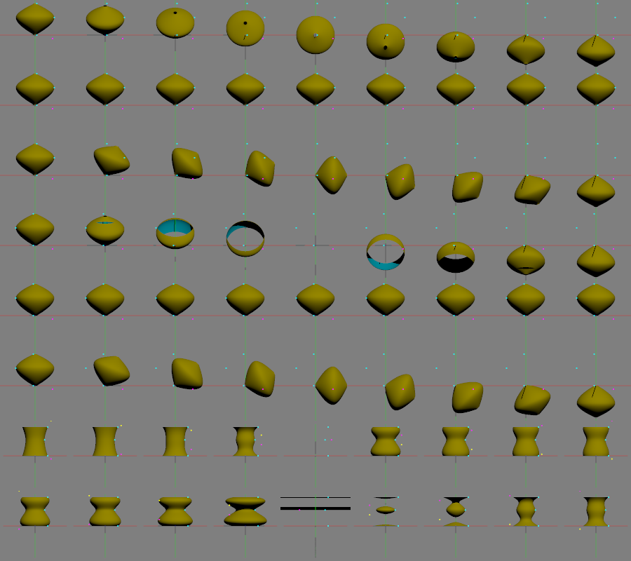
On 9/10/25 11:16, William F Pokorny wrote:
> If you're referring to the sqrt I think you are, you've guessed
> correctly! 🙂 I have a potential fix for it. The sqrt(-) along with some
> fine detail in how std::min(), std::max() work when passed a -nan value
> as the first argument vs the second argument cause the segment blink out
> issue. Only limited testing thus far. Maybe I'll get to more tonight.

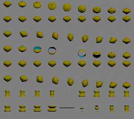
Attached an image of some more testing. It includes the fix for the
segment blink out issue & that fix looks good thus far. For testing I
disabled all the point list sanity checking to see what works and not.

---

Not going to go through the image in detail, but in answer to your
question about on curve points going negative it looks like a no go
without a deep dive and probable re-work of the current code.

For reasons I don't understand, when I allow on curve points to go
negative the camera ray direction affects results. This shown in the
fourth row where the sor slowly disappears then reappears as rotated
about x.

---

The descending in y on curve points doesn't work at all.

---

Allowing the first and last control points to go negative is fine and I
plan to add that relaxing to the blank out fix for yuqk's next release.

---

You had mentioned not being able to flip the two control points in y.
Where everything I'd tried to that point seemed to work. You also
mentioned this bit of code in sor.cpp :

if ((fabs(P[i+2][Y] - P[i][Y]) < gkMinIsectDepthReturned) ||
     (fabs(P[i+3][Y] - P[i+1][Y]) < gkMinIsectDepthReturned))
{
throw POV_EXCEPTION_STRING("Incorrect point in surface of revolution.");
}

I'm finding it is this run time check which sometimes doesn't allow
control points flipping in y. For yuqk what will be in the next release
is some added error text when that check trips so it is easier to
understand what is wrong.

Error! Problem point in sor segment 0 point set.
fabs(P[2][Y] - P[0][Y] || fabs(P[3][Y] - P[1][Y])
fabs(0.5 - 0.5 || fabs(0.9 - 0) < 4.44089e-08

The center images in the bottom two rows(*) of the attached image trip
this check and error. So, that code is catching some 'particular' cases
where given the control point locations relative to other on curve
points doesn't render correctly.

(*) Those rows are start the control points at one extreme and slowly
flip them to the opposite extreme in y moving left to right in the lower
two rows.

---

So with the segment blink out fix, it does look like more could be
allowed as valid point sets for the sor & yuqk will adopt those
relaxations. The shapes with negative control points do break up more
often, but as we found this can happen today with certain point lists.

(I've not really looked at intersections and differences as yet)

Bill P.

Aside: Somewhere I should mentioned too that that blink out fix corrects
the blink out, but in certain cases it also slightly corrects bounding
cylinders where due how min/max work there was no blink out. In other
words some fringe fixes/differences might appear too due the blink out fix.
Post a reply to this message
Attachments:
Download 'sor_testing.png' (114 KB)
Preview of image 'sor_testing.png'
|
|
| |
| |
|
|
|
|
| |
| |
|
|
William F Pokorny <ano### [at] anonymousorg> wrote:

> Attached an image of some more testing. It includes the fix for the
> segment blink out issue & that fix looks good thus far.

So what did you do?

in line 1082
x[n] = sqrt(r[n] * (r[n] * (r[n] * A + B) + C) + D);

I'd suggest changing that something like

x[n] = sqrt( fabs(r[n] * (r[n] * (r[n] * A + B) + C) + D) );


> Not going to go through the image in detail, but in answer to your
> question about on curve points going negative it looks like a no go
> without a deep dive and probable re-work of the current code.

I'd suggest the above, if you haven't already done that.

Also, it may have something to do with calculating the intersections.

There's a check on Radius2 that I saw, so see what happens when you change:

Lines 1110-1111
Radius1 = xmin;
Radius2 = xmax;

to use fabs()

> For reasons I don't understand, when I allow on curve points to go
> negative the camera ray direction affects results. This shown in the
> fourth row where the sor slowly disappears then reappears as rotated
> about x.


> The descending in y on curve points doesn't work at all.

Not surprising - all the checks for the control point order need to be
rewritten.


> You had mentioned not being able to flip the two control points in y.
> Where everything I'd tried to that point seemed to work.

I'll have to do some more experimenting when I get the chance.

> You also
> mentioned this bit of code in sor.cpp :
>
> if ((fabs(P[i+2][Y] - P[i][Y]) < gkMinIsectDepthReturned) ||
>      (fabs(P[i+3][Y] - P[i+1][Y]) < gkMinIsectDepthReturned))
> {
> throw POV_EXCEPTION_STRING("Incorrect point in surface of revolution.");
> }
>
> I'm finding it is this run time check which sometimes doesn't allow
> control points flipping in y.

That def seems to be related to what you're seeing in those last 2 rows - since
the cp's are nearly coincident in y.


> The shapes with negative control points do break up more
> often, but as we found this can happen today with certain point lists.

Do you think as a quick fix, we could just add -ymin to all the values to
translate everything into the first quadrant, starting at y=0, and then
translate everything back after the math gets done?

Very nice that some of this is getting worked out after 30 years.  :)

- BW
Post a reply to this message
|
|
| |
| |
|
|
|
|
| |
| |
|
|
On 9/11/25 10:36, Bald Eagle wrote:
>> Attached an image of some more testing. It includes the fix for the
>> segment blink out issue & that fix looks good thus far.
> So what did you do?

The current fix is:

     if ((r[n] >= y[0]) && (r[n] <= y[1]))
     {
//      x[n] = sqrt(r[n] * (r[n] * (r[n] * A + B) + C) + D);
         double tmpVal = (r[n] * (r[n] * (r[n] * A + B) + C) + D);
         if (tmpVal>=0.0)
             x[n] = sqrt(tmpVal);
         else
         {
             tmpVal = std::abs(tmpVal);
             x[n] = sqrt(tmpVal);
             x[n] *= -1.0;
         }
     }

As for the bounding suggestion, I don't know. Of note is that the
Radius1 value is never used that I see.

Something I did try was faking a user bounding radius multiplier option.
In some configurations where only a subset of the on curve points were
negative in x. It often helped with apparent clipping - but there always
remained some issue with the the ray directions relative to the overall
sor - where all or part of sor 'segment(s)' would drop away (this an
issue apart from the entire-segment blink out issue up top).

My wild guess. There are internally calculated A,B,C,D values used for
the quadratic eqn solved while setting the two bounding radii values.
Those calculated values involve the x values as given for the sor point
set. Maybe something could go 'more right' there when negative values
are present - I don't know.

Bill P.
Post a reply to this message
|
|
| |
| |
|
|
|
|
| |
| |
|
|
I'm still working on unraveling the source code for
bool Sor::Intersect, line 239 in sor.cpp

Line 276 has the interesting expression:  r0 = P[X] * D[Z] - P[Z] * D[X];
and I wasn't sure what that exactly did, especially since the comment that
precedes it is
 /* Get distance of the ray from rotation axis (= y axis). */
and that didn't look like any distance formula that I've ever seen.
The minus sign certainly helped obscure its meaning and purpose.

Apparently it's a sort of 2D cross-product, or "perp-product"

https://s.goessner.net/articles/crossProductHarmful.html
Also being covered in Graphics Gems IV:
Hill, F. S., Jr., The Pleasures of `Perp Dot' Products, p. 138-148.

And since I'm speculating that there are other examples this to be found in
source, I'm documenting this fully here for future reference.

immediately following that, I have a comparison of the length of the ray
direction vector D with some variable "a", which due to poor source code
documentation, I have no idea what "a" exactly is, or why if they are equal that
r0 has to get divided by the sqrt of a.

    #if ((a = Dx * D.x + D.z * D.z) > 0.0)
            #local r0 = r0/sqrt(a);
    #end

I also have Entry->A (through D) which I need to figure out.

- BW
Post a reply to this message
|
|
| |
| |
|
|
|
|
| |
| |
|
|
"Bald Eagle" <cre### [at] netscapenet> wrote:

I have a functional, if not yet rigorous understanding about the ray-radius
intersection test(s).  I am hoping to understand it completely enough to make
one of my explanatory diagrams.

> immediately following that, I have a comparison of the length of the ray
> direction vector D with some variable "a", which due to poor source code
> documentation, I have no idea what "a" exactly is, or why if they are equal that
> r0 has to get divided by the sqrt of a.
>
>     #if ((a = Dx * D.x + D.z * D.z) > 0.0)
>             #local r0 = r0/sqrt(a);
>     #end

I believe I see what's going on here.
in c++, == is a comparison.
= is an assignment.

So the #if line is simultaneously assigning the evaluation of the expression to
a, and then comparing it's value to 0.0.

> I also have Entry->A (through D) which I need to figure out.

This has to do with the arrow operator, or "Class Member Access Operator".

In sor.h, we have

struct Sor_Spline_Entry_Struct final
{
    DBL A, B, C, D;
};

and

struct Sor_Spline_Struct final
{
    int References;
    SOR_SPLINE_ENTRY *Entry;
    BCYL *BCyl;                 /* bounding cylinder.                  */
};

So "Entry" is a pointer to SOR_SPLINE_ENTRY, which has class members A through
D.

"Entry->A" is a whole identifier, which snakes through the 2 structs to identify
and use A.

and

class Sor final : public ObjectBase
{
    public:
        int Number;
        SOR_SPLINE *Spline;      /* List of spline segments     */
.... etc.

So A through D have something to do with the spline segments.
I just don't "see" where they come from or what their exact meaning is.
Perhaps somewhere else farther upstream in the code is a place where the control
points get grouped in sets of 4, and so A through D would be sets of control
points.

- BW
Post a reply to this message
|
|
| |
| |
|
|
|
|
| |
| |
|
|
"Bald Eagle" <cre### [at] netscapenet> wrote:

> So A through D have something to do with the spline segments.
> I just don't "see" where they come from or what their exact meaning is.
> Perhaps somewhere else farther upstream in the code is a place where the control
> points get grouped in sets of 4, and so A through D would be sets of control
> points.

And this is the challenge of trying to do this piecemeal, in fits and starts
during random available 15 min opportunistic time slots.

Just a few lines above that is:

/* Step through the list of intersections. */

    for (j = 0; j < cnt; j++)
    {
        /* Get current segment. */

        Entry = &Spline->Entry[intervals[j].n];

and I'm kinda guessing that intervals comes from insert_hit in
https://github.com/POV-Ray/povray/blob/master/source/core/bounding/boundingcylinder.cpp

So that's my current working theory.
Post a reply to this message
|
|
| |
| |
|
|
|
|
| |
| |
|
|
I also cannot find the following 2 functions in the code repository.
I can't search without being logged in, and username/pswd are scribbled down
somewhere at home.

    MInvTransPoint(P, ray.Origin, Trans);

    MInvTransDirection(D, ray.Direction, Trans);

Anyone?
Post a reply to this message
|
|
| |
| |
|
|
|
|
| |
| |
|
|
hi,

"Bald Eagle" <cre### [at] netscapenet> wrote:
> I also cannot find the following 2 functions in the code repository.
> I can't search without being logged in, and username/pswd are scribbled down
> somewhere at home.
>
>     MInvTransPoint(P, ray.Origin, Trans);
>
>     MInvTransDirection(D, ray.Direction, Trans);
>
> Anyone?

core/math/matrix.h has the prototypes, hth.

and thx re other thread.


regards, jr.
Post a reply to this message
|
|
| |
| |
|
|
|
|
| |
| |
|
|
"jr" <cre### [at] gmailcom> wrote:
> hi,
>
> "Bald Eagle" <cre### [at] netscapenet> wrote:
> > I also cannot find the following 2 functions in the code repository.
> > I can't search without being logged in, and username/pswd are scribbled down
> > somewhere at home.
> >
> >     MInvTransPoint(P, ray.Origin, Trans);
> >
> >     MInvTransDirection(D, ray.Direction, Trans);
> >
> > Anyone?
>
> core/math/matrix.h has the prototypes, hth.
>
> and thx re other thread.
>
>
> regards, jr.

Thanks, jr!

Ah, I think I (mostly) understand now.
matrix.h declares those inline functions for use in the namespace, and the
MInvTransPoint and MInvTransDirection functions just use the
MTransPoint and MTransDirection functions but somehow using the multiplicative
inverse of the transform matrix as input instead of the regular matrix.

in matrix.cpp, (line 535) we have

void Compute_Scaling_Transform (TRANSFORM *result, const Vector3d& vector)
{
    MIdentity (result->matrix);

    (result->matrix)[0][0] = vector[X];
    (result->matrix)[1][1] = vector[Y];
    (result->matrix)[2][2] = vector[Z];

    MIdentity (result->inverse);

    (result->inverse)[0][0] = 1.0 / vector[X];
    (result->inverse)[1][1] = 1.0 / vector[Y];
    (result->inverse)[2][2] = 1.0 / vector[Z];
}

and at line 155, there is:

void MIdentity (MATRIX result)
{
    int i, j;

    for (i = 0; i < 4; i++)
    {
        for (j = 0; j < 4; j++)
        {
            if (i == j)
            {
                result[i][j] = 1.0;
            }
            else
            {
                result[i][j] = 0.0;
            }
        }
    }
}

I'm still trying to get a feel for all of this, having only ever coded in "c++"
(Arduino) for maybe 6 months, several years back.

(Currently reading www.learncpp.com in small spurts, then I'll probably start
going through things with Stroustrup in hand to more rigorously work things
out.)

I guess perhaps in the same way that we can have operator overloading, where I
have two functions with the same name, but different input types,
a single function can yield one of several different types of outputs if that
class member access operator -> is used ...?

- BW
Post a reply to this message
|
|
| |
| |
|
|
|
|
| |
| |
|
|
"Bald Eagle" <cre### [at] netscapenet> wrote:

> bool Sor::Intersect, line 239 in sor.cpp
>
> Line 276 has the interesting expression:  r0 = P[X] * D[Z] - P[Z] * D[X];

>  /* Get distance of the ray from rotation axis (= y axis). */
....
> Apparently it's a sort of 2D cross-product, or "perp-product"
....
>     #if ((a = Dx * D.x + D.z * D.z) > 0.0)
>             #local r0 = r0/sqrt(a);
>     #end

OK, so r0 gets calculated by taking the vector cross product of
the PROJECTIONS of the ray origin and the ray direction (after they have been
translated into "object space")
[still hunting down how that Trans gets calculated, but I have an idea]

So, since they are projections onto the xz plane, y=0 for both vectors.
that means that two of the 2x2 determinants drop out due to multiplication by 0,
leaving only the one determinant to multiply by the y basis vector,
giving a y vector that is parallel to the 2 projected vectors.

Thus the shortened form P[X] * D[Z] - P[Z] * D[X]

However, in working this out, I had my vectors in different places in the
matrix, and so I got P[Z] * D[X] - P[X] * D[Z] which should just be the opposite
sign of the calculation in code.  Not really a worry, since it's just a vector
cross product.

The potential problem that I see is the test that uses this value:

    /* Test if ray misses object's bounds. */

    #if (r0 > Radius2)                      // Radius2 is xmax of the sor CP's
        #local Result = false;
    #else

If the sign of the vector cross product is negative, then that rejection test
will always fail, and the ray will always move on to have the intersection
tested.   Which, if I'm interpreting all of this correctly, means that all of
the rays on one side of the sor always get fully evaluated for intersections,
this potentially making rendering slower than it needs to be.

Shouldn't we be using at least abs (r0) to account for P-cross-D AND D-cross-P?


In more detail:

First we translate and then normalize the ray direction vector.

Then we test the ray to see if it is above or below the sor
as well as to the left or right of the sor

starting at line 266
    if (((D[Y] >= 0.0) && (P[Y] >  Height2)) ||
        ((D[Y] <= 0.0) && (P[Y] <  Height1)) ||
        ((D[X] >= 0.0) && (P[X] >  Radius2)) ||
        ((D[X] <= 0.0) && (P[X] < -Radius2)))
    {
        return(false);
    }

Line 266 checks if the ray direction is flat or points up, and the ray origin is
higher than the highest sor control point (Height2 = ymax)
So it will never intersect the rotated sor spline
This is OK

Line 267 checks if the ray direction is flat or points down, and the ray origin
is lower than the lowest sor control point (Height1 = ymin)
So it will never intersect the rotated sor spline
This is OK

Line 268 checks if the ray direction is straight or points right, and the ray
origin is to the right of the rightmost sor control point (Radius2 = xmax)
So it will never intersect the rotated sor spline
This is OK

Line 269 checks if the ray direction is straight or points left, and the ray
origin is to the left of the leftmost (rotated) sor control point (-Radius2 =
-xmax)
So it will never intersect the rotated sor spline
This is OK

BW: since this is before we do any projection, and we're only testing height and
width, can't we have a slanted ray that WOULD intersect the sor spline once it
got rotated around the y-axis?

Then we are doing a calculation that purports to be the DISTANCE between the ray
and the y-axis.

Working that out from first principles, it is the geometric problem of
determining the perpendicular distance (the shortest distance) between a point
and a line.
We simplify this by projecting onto 2D since the vertical angle of the ray makes
no difference at this point.
The vector cross product of 2 vectors gives us the area of the parallelogram
defined by those 2 vectors (just use those 2 vectors to make the remaining 2
sides)
The area is also equal to the base times the height of the parallelogram, and so
we solve for the height (H), which is the perpendicular - and therefore the
shortest distance between the point (y-axis in the xz plane, <0, 0, 0>) and the
line (the ray composed of origin and unit directional vector)
That gives us LENGTH (P-cross-D) = H times LENGTH (D)
Rearranging gives us H = LENGTH (P-cross-D) / LENGTH (D)

Now, in code, we have
r0 = P.x * D.z - P.z * D.x;
and that is only multiplied by the y unit basis vector,
so since there are no other dimensional units, this directly evaluates to the
length of the perpendicular y vector, and we don't have to do the expensive
square root of the sum of the squares.

a is the squared length of the direction vector
which, if non-zero, the vector cross product length gets divided by,
which should be the shortest, perpendicular length.

A few minor problems.
The ray direction vector already gets normalized at the beginning of
Sor_Intersect, so why are we calculating it's length again, and then checking if
it's more than zero, when at this point it should always be ONE.
Which bring up the potential divide-by-zero error when the normalization
calculation is done - and there is NO checking THERE!
And then there is the vector cross product sign issue.

So, after this gets rigorously checked, I'd suggest that
1. the ray direction vector length check gets moved to earlier in the code
2. we can do away with recalculating the length, checking for non-zero length,
and dividing the vector cross product length by a ray length which should
already always be 1.
3. Line 276 r0 = P[X] * D[Z] - P[Z] * D[X];
should be r0 = fabs(P[X] * D[Z] - P[Z] * D[X]);
so that the "length" is always positive.

- BE
Post a reply to this message
|
|
| |
| |
|
|
|
|
| |
| |
|
|
"giving a y vector that is parallel to the 2 projected vectors."

Clearly I meant to write perpendicular.
Post a reply to this message
|
|
| |
| |
|
|
|
|
| |
| |
|
|
"BW: since this is before we do any projection, and we're only testing height
and
width, can't we have a slanted ray that WOULD intersect the sor spline once it
got rotated around the y-axis?"

This was meant to be deleted, after I had worked all that out.
Post a reply to this message
|
|
| |
| |
|
|
|
|
| |
| |
|
|
"Bald Eagle" <cre### [at] netscapenet> wrote:

>     MInvTransPoint(P, ray.Origin, Trans);
>
>     MInvTransDirection(D, ray.Direction, Trans);


Now I can't really find if and where Trans gets defined as anything but an
Identity matrix in Line 776.

The sor gets created "at the origin" / around the y-axis,
so I'm now presuming that when we do
sor { ... translate <x, y, z>}

that the sor gets created and evaluated in its default position, and then all of
the results just get filtered through the translate transform as a
post-intersection process.

And if THAT's the case, then why do we have all of the transforms in the various
functions when we don't need them?

But then again, I could be missing something, and be completely wrong.

- BE
Post a reply to this message
|
|
| |
| |
|
|
|
|
| |
| |
|
|
"Bald Eagle" <cre### [at] netscapenet> wrote:

> a is the squared length of the direction vector
> which, if non-zero, the vector cross product length gets divided by,
> which should be the shortest, perpendicular length.

a is the squared length of the PROJECTED direction vector

> A few minor problems.
> The ray direction vector already gets normalized at the beginning of
> Sor_Intersect, so why are we calculating it's length again, and then checking if
> it's more than zero, when at this point it should always be ONE.

Because although the RAY is normalized, it's PROJECTION isn't unit-length unless
it's parallel to the xz plane.

> Which bring up the potential divide-by-zero error when the normalization
> calculation is done - and there is NO checking THERE!
> And then there is the vector cross product sign issue.
>
> So, after this gets rigorously checked, I'd suggest that
> 1. the ray direction vector length check gets moved to earlier in the code

> 3. Line 276 r0 = P[X] * D[Z] - P[Z] * D[X];
> should be r0 = fabs(P[X] * D[Z] - P[Z] * D[X]);
> so that the "length" is always positive.

- BE
Post a reply to this message
|
|
| |
| |
|
|
|
|
| |
| |
|
|
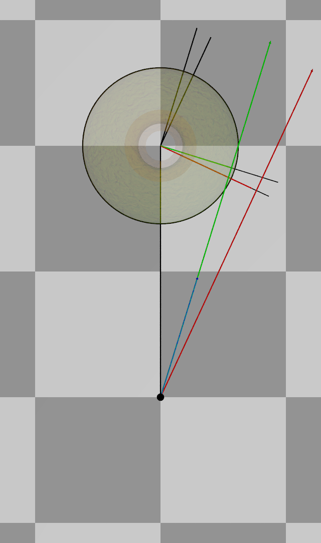
"Bald Eagle" <cre### [at] netscapenet> wrote:

> r0 = P.x * D.z - P.z * D.x;
> and that is only multiplied by the y unit basis vector,
> so since there are no other dimensional units, this directly evaluates to the
> length of the perpendicular y vector, and we don't have to do the expensive
> square root of the sum of the squares.
>
> a is the squared length of the [NORMALIZED and PROJECTED] direction vector
> which, if non-zero, the vector cross product length gets divided by,
> which should be the shortest, perpendicular length.

So what happens is that the "perp dot product" is essentially taking one vector,
rotating it counterclockwise by 90 degrees, and then taking the dot product,
which projects one vector onto the other.
This gives its projected length along the other vector.

And that's supposed to give the perpendicular, shortest distance between the
origin and the ray.

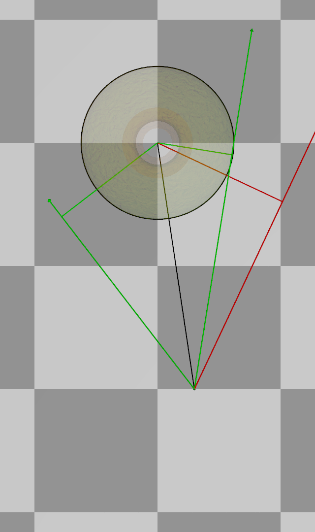
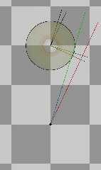
Diagrammatically, it's all looking good, but for some strange reason, the
perpendicular distance seems to be shorter than it should be, with the error
increasing the farther away the ray is.

- BW

If anyone has any ideas what the source of this error is, I'm all ears.
Post a reply to this message
Attachments:
Download 'sor_diagram1.png' (130 KB)
Preview of image 'sor_diagram1.png'
|
|
| |
| |
|
|
|
|
| |
| |
|
|
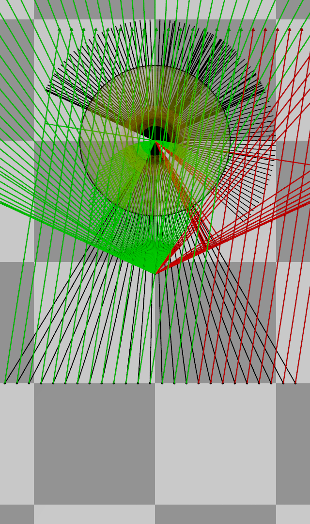
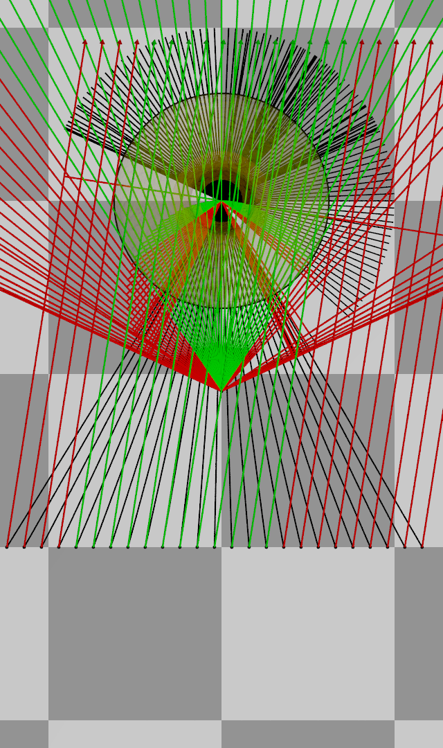
GOT IT.

OK, so I am pretty confident that I have the whole initial bounding-test section
of the code worked out.

And that has led me to prove that one problem I thought was happening IS
happening,

and

there's another issue that is taking place that might explain why sometimes some
of the segments fail to render.

> Diagrammatically, it's all looking good, but for some strange reason, the
> perpendicular distance seems to be shorter than it should be, with the error
> increasing the farther away the ray is. (*)

1. The rays that give a negative perpendicular dot product erroneously test as
hitting the bounding cylinder, and so a bunch of root solving gets done that
shouldn't be.

1a.  The code tests a bounding cylinder that is based on the largest diameter of
the whole sor {}.   But the sor {} is not so much a single object as it is a
stack of individual segments.
I believe that we ought to be testing intersection with each individual segment
to optimize the bounding tests.

2. The issue (*) above was a result of the ray direction being used as-is.
When I had an angled ray, the length was too large, and overly shortened my
perpendicular vector.
When I only used the ray projection onto the xz plane, all of my perpendicular
vectors were of the proper length.

2a.  This too-short vector projection likely leads to false positives and causes
additional unnecessary root-finding.


So, I would like to propose 2 correction to this section of the sor {} source.

1. replace
D = ray.Direction;
with
D = <ray.Direction.x, 0, ray.Direction.z>;

and
2. replace
#if (r0 > Radius2)
with
#if (fabs(r0) > Radius2)


The attached diagram is a mess, but what we have is the sor {} circled in black
with the radius equal to the greatest x-value of the control points.

along the bottom, the ray origin changes, and the direction vector stays the
same, resulting in a sweep from left to right.  As you can (hopefully) see, the
parallel lines change from green to red.
The green lines signify a successful _intersection test_ of the ray with the
bounding cylinder.  The red are fails.
The thing to notice here is that only the misses to the right actually fail the
intersection test.
All of the rays on the left pass the test and go on to calculate the roots of
where the ray intersects the polynomial.

The fan shape above that is holding the ray origin fixed, while making the ray
direction go around in a circle 360 degrees.
The same false positive issue occurs.

Next post will fix that with fabs(r0)
Post a reply to this message
Attachments:
Download 'sor_diagram1.png' (524 KB)
Preview of image 'sor_diagram1.png'
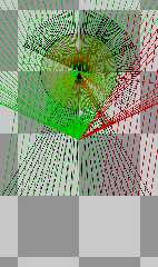
|
|
| |
| |
|
|
|
|
| |
| |
|
|
"Bald Eagle" <cre### [at] netscapenet> wrote:

> Next post will fix that with fabs(r0)

As you can see, there is a lot more red in this render, showing the removal of
erroneous bounding intersection positives, and the rays fail on both the left
and the right now, with only the rays that actually intersect the bounding
cylinder triggering the root-solving phase.
Post a reply to this message
Attachments:
Download 'sor_diagram1.png' (522 KB)
Preview of image 'sor_diagram1.png'
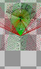
|
|
| |
| |
|
|
|
|
| |
| |
|
|
And here is a much simplified diagram showing only 3 rays, with all extraneous
lines removed.

Only the rays and the perpendicular distances are shown, color coded for
bounding intersection test state.
Post a reply to this message
Attachments:
Download 'sor_diagram1.png' (134 KB)
Preview of image 'sor_diagram1.png'
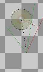
|
|
| |
| |
|
|
|
|
| |
| |
|
|
Desmos live graphing

Move the ray origin or the direction vector endpoint.
Very useful for working things out.

https://www.desmos.com/calculator/o50ybsmkw3

- BE
Post a reply to this message
|
|
| |
| |
|
|
|
|
| |
|
|