|
 |
GOT IT.
OK, so I am pretty confident that I have the whole initial bounding-test section
of the code worked out.
And that has led me to prove that one problem I thought was happening IS
happening,
and
there's another issue that is taking place that might explain why sometimes some
of the segments fail to render.
> Diagrammatically, it's all looking good, but for some strange reason, the
> perpendicular distance seems to be shorter than it should be, with the error
> increasing the farther away the ray is. (*)
1. The rays that give a negative perpendicular dot product erroneously test as
hitting the bounding cylinder, and so a bunch of root solving gets done that
shouldn't be.
1a. The code tests a bounding cylinder that is based on the largest diameter of
the whole sor {}. But the sor {} is not so much a single object as it is a
stack of individual segments.
I believe that we ought to be testing intersection with each individual segment
to optimize the bounding tests.
2. The issue (*) above was a result of the ray direction being used as-is.
When I had an angled ray, the length was too large, and overly shortened my
perpendicular vector.
When I only used the ray projection onto the xz plane, all of my perpendicular
vectors were of the proper length.
2a. This too-short vector projection likely leads to false positives and causes
additional unnecessary root-finding.
So, I would like to propose 2 correction to this section of the sor {} source.
1. replace
D = ray.Direction;
with
D = <ray.Direction.x, 0, ray.Direction.z>;
and
2. replace
#if (r0 > Radius2)
with
#if (fabs(r0) > Radius2)
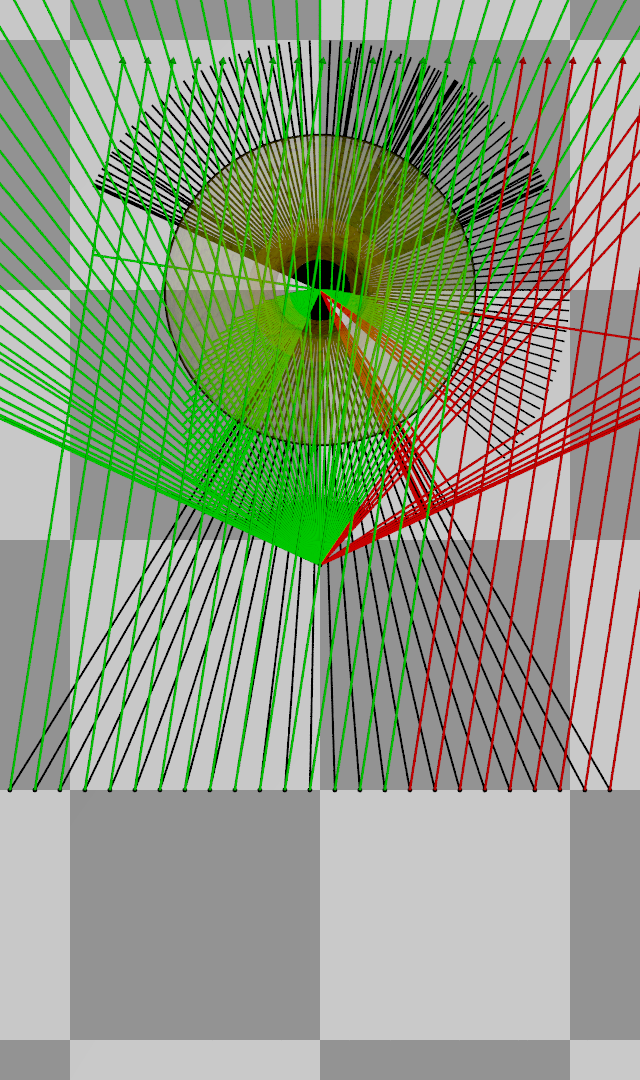
The attached diagram is a mess, but what we have is the sor {} circled in black
with the radius equal to the greatest x-value of the control points.
along the bottom, the ray origin changes, and the direction vector stays the
same, resulting in a sweep from left to right. As you can (hopefully) see, the
parallel lines change from green to red.
The green lines signify a successful _intersection test_ of the ray with the
bounding cylinder. The red are fails.
The thing to notice here is that only the misses to the right actually fail the
intersection test.
All of the rays on the left pass the test and go on to calculate the roots of
where the ray intersects the polynomial.
The fan shape above that is holding the ray origin fixed, while making the ray
direction go around in a circle 360 degrees.
The same false positive issue occurs.
Next post will fix that with fabs(r0)
Post a reply to this message
Attachments:
Download 'sor_diagram1.png' (524 KB)
Preview of image 'sor_diagram1.png'
|
|