I found the cause(s) of that small circle in the bump_map appearance. It is a
combination of two different things:
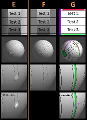
1) a gray value *difference* between the left and right edges of the applied
image (see column E). The circle seems to be a natural consequence of this
difference. My guess is that the 'normals' mechanism under-the-hood needs(?) to
use the gray values from BOTH left and right to figure out what the normal
should be at that circle 'point'. Or possibly it's a precision issue.
2) using 'interpolate 2' in the bump_map, which makes the circle even worse. In
this case, the resulting normal definitely appears to be using the
left-and-right edges of the image for the interpolation.
Column F shows the normals result when the applied image has the SAME gray
values on the left and right-- NO circle is produced, whether or not interpolate
2 is also used. But such an applied image is not a realistic test; it will
usually have natural grayscale differences on the left and right, like LanuHum's
original pattern of a tilted wave.
Column G shows that NO 'circle' is produced when a typical pigment{image_map...}
is applied instead of a bump_map-- unless 'interpolate 2' is used, which then
'blends' the left and right edge colors of the image_map.
Post a reply to this message
Attachments:
Download 'bump_map_circle_vs_pigment_image_map_kw_3_28_26.jpg' (510 KB)
Preview of image 'bump_map_circle_vs_pigment_image_map_kw_3_28_26.jpg'
|


