|
|
|
|
|
|
| |
| |
|
|
|
|
| |
| |
|
|
clipka <ano### [at] anonymous org> wrote:
> I can imagine what patterns you have in mind, but I still only have a
> vague idea what "direct access" you envision for them.
As you say below, POV-Ray has internal methods of computing pattern values
computed from individual points. I would guess that there may be a way to -
compute the 2nd derivative of such a function to get maxima/minima as inflection
points, and perhaps provide a general means for "pulling out" those values - so
that the user doesn't have to do a loop with sufficient fineness to test for a 0
or 1 ....
> That's a lot, I guess ;)
> Obviously, some of them are /not/ available as POV-Ray patterns, so what
> about them?
Add some of them? :P
Where there's a discontinuity in value of nearby points, there's
> a node; where there is only a gradual change, there isn't.
True, though there maybe a way to narrowly specify values of 0, 0.5, 1 ....
> Various of the patterns you mentioned don't even have point-like nodes,
> and just have line-like or surface-like discontinuities. The wood
> pattern is one such example: It has one central line-like discontinuity,
> with concentric cylinder-like discontinuities at regular distances.
Yes. I can envision rendering concentric cylinders by such a means, or
intersecting that locus of points with another pattern with point-like nodes, or
anything else to get only a subset of that - I'm just looking to get a few
different example to get started with an illustrate the possibilities.
> And even when patterns do exhibit point-like nodes, any application of
> even the slightest turbulence would make it impossible to identify their
> effective resulting location: "backtracking" POV-Ray's turbulence warp
> is, to my knowledge, not feasible.
You're working backwards in that case. If there's a way to replicate the means
by which POV-Ray creates the pattern and applies the turbulence, then the user
could do that in a forward-fashion, which must be feasible since POV-Ray already
does it..
> > They could also form the basis for [...snip]
> Now you again have me at the disadvantage of not understanding what you
> mean :)
Let's suppose there's a pattern for a crystal structure, and a sphere is plotted
at the origin. I might do something like use a slightly larger sphere to do
insidedness tests on the points of the crystal-pattern and place narrow
cylinders from the origin out to all of those points - to give a sort of defined
type of stellation.
like the following, only with non-random endpoints:
http://www.f-lohmueller.de/pov_tut/random/random8e.htm
If instead I used those points as bases of cones with all the peaks at the
origin, I could have cones radiate out from the center in a defined manner.
Maybe they're hollow - maybe they're subtracted from the sphere, maybe there's
no sphere and the cylinders are all just merged.
> > How will this work? What will people use it for?
> > How the heck do I know?
>
> I guess that's the crux of the matter ;)
To me, it's the HOW. The _what_ will follow.
> That may be a reasonable approach. Aside from the crackle pattern, I
> don't think it would be reasonable to even attempt to implement such
> stuff in POV-Ray proper.
I think Jerome would have a blast doing a few of these - he always seems like
he's up for the challenges ;) He's got some wild stuff on that wiki page of
his. org> wrote:
> I can imagine what patterns you have in mind, but I still only have a
> vague idea what "direct access" you envision for them.
As you say below, POV-Ray has internal methods of computing pattern values
computed from individual points. I would guess that there may be a way to -
compute the 2nd derivative of such a function to get maxima/minima as inflection
points, and perhaps provide a general means for "pulling out" those values - so
that the user doesn't have to do a loop with sufficient fineness to test for a 0
or 1 ....
> That's a lot, I guess ;)
> Obviously, some of them are /not/ available as POV-Ray patterns, so what
> about them?
Add some of them? :P
Where there's a discontinuity in value of nearby points, there's
> a node; where there is only a gradual change, there isn't.
True, though there maybe a way to narrowly specify values of 0, 0.5, 1 ....
> Various of the patterns you mentioned don't even have point-like nodes,
> and just have line-like or surface-like discontinuities. The wood
> pattern is one such example: It has one central line-like discontinuity,
> with concentric cylinder-like discontinuities at regular distances.
Yes. I can envision rendering concentric cylinders by such a means, or
intersecting that locus of points with another pattern with point-like nodes, or
anything else to get only a subset of that - I'm just looking to get a few
different example to get started with an illustrate the possibilities.
> And even when patterns do exhibit point-like nodes, any application of
> even the slightest turbulence would make it impossible to identify their
> effective resulting location: "backtracking" POV-Ray's turbulence warp
> is, to my knowledge, not feasible.
You're working backwards in that case. If there's a way to replicate the means
by which POV-Ray creates the pattern and applies the turbulence, then the user
could do that in a forward-fashion, which must be feasible since POV-Ray already
does it..
> > They could also form the basis for [...snip]
> Now you again have me at the disadvantage of not understanding what you
> mean :)
Let's suppose there's a pattern for a crystal structure, and a sphere is plotted
at the origin. I might do something like use a slightly larger sphere to do
insidedness tests on the points of the crystal-pattern and place narrow
cylinders from the origin out to all of those points - to give a sort of defined
type of stellation.
like the following, only with non-random endpoints:
http://www.f-lohmueller.de/pov_tut/random/random8e.htm
If instead I used those points as bases of cones with all the peaks at the
origin, I could have cones radiate out from the center in a defined manner.
Maybe they're hollow - maybe they're subtracted from the sphere, maybe there's
no sphere and the cylinders are all just merged.
> > How will this work? What will people use it for?
> > How the heck do I know?
>
> I guess that's the crux of the matter ;)
To me, it's the HOW. The _what_ will follow.
> That may be a reasonable approach. Aside from the crackle pattern, I
> don't think it would be reasonable to even attempt to implement such
> stuff in POV-Ray proper.
I think Jerome would have a blast doing a few of these - he always seems like
he's up for the challenges ;) He's got some wild stuff on that wiki page of
his.
Post a reply to this message
|
|
| |
| |
|
|
|
|
| |
| |
|
|
Tor Olav <tor### [at] TOBEREMOVEDgmailcom> wrote:
> Have you looked at the source code for these images ?
Just saw this now.
Nope - but I will :)
> I'm sure that it can be be done with non rectangular/cubic space
> divisions as well.
I'll think it over - I'm sure it can - I just thought perhaps the folks who've
already implemented the existing patterns would have a huge head start at
figuring out exactly how.
> R Suzuki once made some interesting (but quite complex) isosurface
> macros that might be relevant:
Thanks for those - I'll look them over :)
Post a reply to this message
|
|
| |
| |
|
|
|
|
| |
| |
|
|
Am 18.07.2016 um 21:16 schrieb Bald Eagle:
> clipka <ano### [at] anonymousorg> wrote:
>
>> I can imagine what patterns you have in mind, but I still only have a
>> vague idea what "direct access" you envision for them.
>
> As you say below, POV-Ray has internal methods of computing pattern values
> computed from individual points. I would guess that there may be a way to -
> compute the 2nd derivative of such a function to get maxima/minima as inflection
> points, and perhaps provide a general means for "pulling out" those values - so
> that the user doesn't have to do a loop with sufficient fineness to test for a 0
> or 1 ....
The 2nd derivative /per se/ doesn't help you much -- you'd need to solve
for its "roots", i.e. the locations where that function happens to
evaluate to 0. That's quite trivial for polynomials, but only few of
POV-Ray's patterns are polynomial functions.
Also, as mentioned before, the set of "roots" may actually be a
contiguous set of points, such as a line or surface. How would you even
convey the result of such a test?
>> And even when patterns do exhibit point-like nodes, any application of
>> even the slightest turbulence would make it impossible to identify their
>> effective resulting location: "backtracking" POV-Ray's turbulence warp
>> is, to my knowledge, not feasible.
>
> You're working backwards in that case. If there's a way to replicate the means
> by which POV-Ray creates the pattern and applies the turbulence, then the user
> could do that in a forward-fashion, which must be feasible since POV-Ray already
> does it..
No, it's really not possible.
Whith POV-Ray's raytracing and pattern evaluation, you take a point in
3D space (typically on the surface of an object), P, shove it into a
turbulence function, Q=f_turb(P), which returns another point, Q, which
is then shoved into a pattern function (or algorithm), V=f_pat(Q),
returning a scalar value V. There are points where that resulting value
changes significantly even with small changes in Q -- those are the ones
that you're interested in.
Suppose you could actually identify one such points: You get a point Q.
To know where that point ends up in true 3D space, you'd have to shove
it into the _inverse_ of the turbulence function, P=f_turb_inv(Q).
But the turbulence function isn't easily invertible.
Post a reply to this message
|
|
| |
| |
|
|
|
|
| |
| |
|
|
TOK,
Thanks for the pointers to R Suzuki's work :)
You and he seem like two peas from the same pod.
"#declare function = function of a function of a function...." :D
It's certainly made for some interesting reading, and there's a lot of good
things for me to think about with all that you and he have talked about.
I wish I could have spent more time pov-ing in graduate school ;)
It looks to me that other people have had somewhat similar interests way back
when:
http://news.povray.org/povray.general/thread/%3CX### [at] 204213191226%3E/?ttop=284668&toff=4500
I think I see what you're doing in terms of "subdividing space" using the SELECT
operation in functions. It will probably take me a little while to whittle
things down to a level where I can start to explore that in a meaningful way,
but I definitely see the shape of what you're doing out at the horizon.
Again, many thanks!
Post a reply to this message
|
|
| |
| |
|
|
|
|
| |
| |
|
|
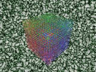
First time I've had enough of a chance to dissect things and start to play with
this.
This baby-step took 10 min 13 sec to render (all one isosurface).
Post a reply to this message
Attachments:
Download 'spacedivisionexperiments.png' (809 KB)
Preview of image 'spacedivisionexperiments.png'
|
|
| |
| |
|
|
|
|
| |
| |
|
|
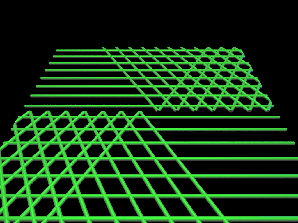
I've played around a bunch with some basic ideas.
I think I need to explore moving things "off-axis" with some rotations, if I can
figure out how to do that inside of the function itself.
Then perhaps introduce some sort of alternating pattern.
Post a reply to this message
Attachments:
Download 'spacedivisionexperiments cylindrical grid.png' (1521 KB)
Preview of image 'spacedivisionexperiments cylindrical grid.png'
|
|
| |
| |
|
|
|
|
| |
| |
|
|
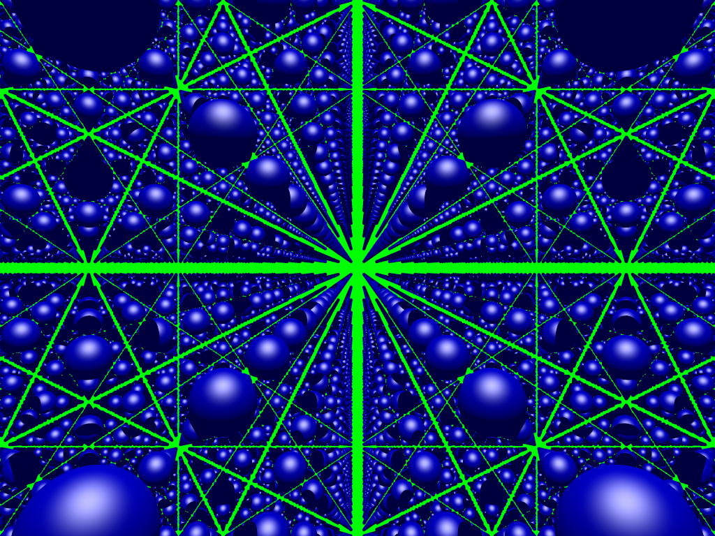
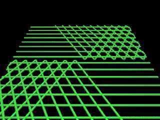
Ok, so I have managed to introduce some rotation off of the primary axes, but
have somehow introduced an unexpected discontinuity.
Perhaps someone better versed in math, isosurfaces, and modular arithmetic can
spot what's going on and identify a solution.
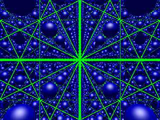
Here's my first stab at a triangular grid - I didn't bother to pretty it up or
adjust the primary z cylinders to intersect at the same point as the pi/6
rotated ones.
Post a reply to this message
Attachments:
Download 'spacedivisionexperiments.png' (202 KB)
Preview of image 'spacedivisionexperiments.png'
|
|
| |
| |
|
|
|
|
| |
| |
|
|
I started with this stuff from TOK,
#declare Spacing = 10;
#declare Xspc = Spacing;
#declare Yspc = Spacing;
#declare Zspc = Spacing;
#declare HalfXspc = Xspc/2;
#declare HalfYspc = Yspc/2;
#declare HalfZspc = Zspc/2;
// returns opposite sign Halfspc except for 0.
#declare XFn = function(x) { mod(x, Xspc) - select(x, -HalfXspc, 0, HalfXspc) }
#declare YFn = function(y) { mod(y, Yspc) - select(y, -HalfYspc, 0, HalfYspc) }
#declare ZFn = function(z) { mod(z, Zspc) - select(z, -HalfZspc, 0, HalfZspc) }
added
#declare Theta = pi/6;
#declare Theta2 = -pi/6;
#declare XRotate = function { x*cos(Theta) + z*sin(Theta)}
#declare ZRotate = function { x*cos(Theta) + z*sin(Theta)}
#declare ZRotate2 = function { x*cos(Theta) + z*sin(Theta2)}
based on
https://en.wikipedia.org/wiki/Rotation_of_axes
equation 5
figured I needed new sets of equations to partition the plane based on the
rotated axes
#declare XPrimeFn = function { mod(XRotate(x, y, z), Xspc) - select(x,
-HalfXspc, 0, HalfXspc) }
//#declare YPrimeFn = function { mod(y, Yspc) - select(y, -HalfYspc, 0,
HalfYspc) }
#declare ZPrimeFn = function { mod(ZRotate(x, y, z), Zspc) - select(z,
-HalfZspc, 0, HalfZspc) }
#declare ZPrimeFn2 = function { mod(ZRotate2(x, y, z), Zspc) - select(z,
-HalfZspc, 0, HalfZspc) }
Then I use these to generate my 3 isosurfaces:
#declare GridFunction1 = function { sqrt(pow(ZFn(z),2) + pow(y,2)) - 1 }
#declare GridFunction2 = function { sqrt(pow(ZPrimeFn(x, y, z),2) + pow(y,2)) -
1 }
#declare GridFunction3 = function { sqrt(pow(ZPrimeFn2(x, y, z),2) + pow(y,2)) -
1 }
Post a reply to this message
|
|
| |
| |
|
|
|
|
| |
|
|