|
|
|
|
|
|
| |
| |
|
|
|
|
| |
| |
|
|
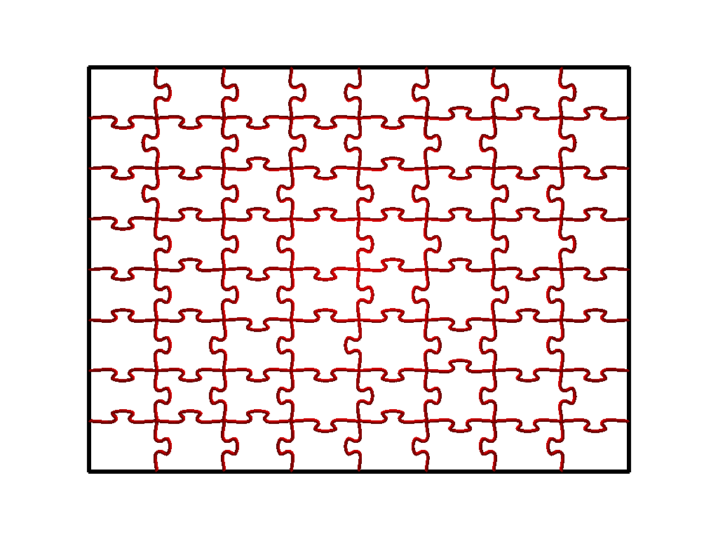
I'm attempting to create a jigsaw puzzle -
because apparently I can't find any sort of software that will just create the
cut paths for any size / number of pieces, with good variation of piece shape.
I've worked out the simple grid of pieces, using splines to generate the
interlocking tab shape, and am going to add some variation to that - moving the
tab position and possibly varying the size and shape by randomly shifting and
scaling the spline coordinates within certain constraints.
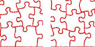
I think I can work that out, but the part that I'm struggling to grasp is how I
get the interesting "offset", or what I call a sort of "double-corner" since 4
pieces don't line up at a single corner - there are now two, either in the X or
the Y direction. (See image in next post)
I was wondering if anyone had any suggestions about how to achieve this effect
programmatically, or could describe a solution clearly enough or in pseudo-code
so that I could begin to effectively implement it.
Thanks!
===================================================================
cylinder{z,z*1.1,.65 pigment{cylindrical rotate x*90 color_map{[0 rgb<1,.2,0>]
[1 rgb xy]}}}#macro C(D,S,F,M)sin(radians(D+(F*90)+(i*S)))*A+M#end#local L=.9;
#local A=0.3125;#local i=0;#local T=.014;#macro
R(X,Y,D,S,M,N)cylinder{<X,Y,L>,<C(D,S,1,M),C(D,S,0,N),L>T}#end#macro
V(X,Y,Z,P,J,K,Q,U)cone{<X,Y,Z>P<J,K,Z>Q pigment{rgb U}}#end#while(i<8)#local
F=R(-0.243,.113,170,20,-.415,.069) #local
W=difference{R(-.172+(i/80),.328,250,5,-0.18,0.18)sphere {<-.14,.22,L>A/2.4}}
union{object{F}object{F scale-x*1}object{W}object{W scale-x*1}
cylinder{<.004,.095,L>,<-.007,-.18,L>,.1}pigment{Brown}}
cylinder{<-.008,-0.03,L>,<C(240,10,1,-.028),C(240,10,0,-.09),L>.014 pigment{rgb
1}}V(-.01,.095,L,.08,.003,.28,.021,1)V(-.001,.2,.85,0,.01,.26,.028,0)
V(.019,.23,.83,0,.026,.25,.01,xy)sphere{<.005,.25,.82>.002 pigment{rgb
1}}#declare i=i+1;#end
===================================================================
Post a reply to this message
Attachments:
Download 'jigsawpuzzle.png' (101 KB)
Preview of image 'jigsawpuzzle.png'
|
|
| |
| |
|
|
|
|
| |
| |
|
|
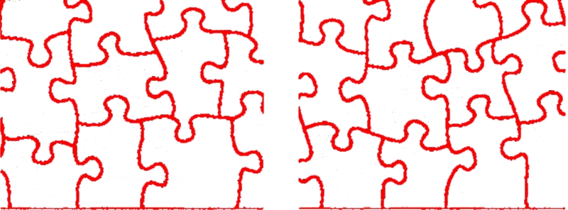
And here is the effect I'm trying to achieve.
Post a reply to this message
Attachments:
Download 'complexpieces.jpg' (170 KB)
Preview of image 'complexpieces.jpg'
|
|
| |
| |
|
|
|
|
| |
| |
|
|
"Bald Eagle" <cre### [at] netscape net> wrote:
> And here is the effect I'm trying to achieve.
The first example would be easier to achieve. You could use a set of
pre-defined "cutting dies" and associated rules for matching them on the edges,
but that could look too regular, and there'd be pieces that were shaped the same
way.
you could generalize just the edge types and try to create rules for matching
them on the corners, but that would be more complicated.
another way would be to do a series of horizontal and vertical cuts along paths
with perturbations based on a set of rules. I'd start by determining the
endpoints, perhaps ensuring that the midpoint of the line fell within a certain
range, and then subdivide and perturb the line in between the pre-determined
endpoint.
you could use a variant of the first method here, with just the edge dies that
you then use to perturb the line between your pre-determined endpoints,
adjusting each consecutive die so that it lines up with your pre-determined
midline and then doing a flip or a 180 rotate to make the edge more random.
for something truly random, you would need to be more tricky.
This post on mathematica.stackexchange says it better than I ever could
http://mathematica.stackexchange.com/questions/6706/how-can-i-calculate-a-jigsaw-puzzle-cut-path
It looks like they're using a modified voronoi diagram (crackle pattern) and
then modifying the edges with tongues and slots. No idea how you'd do that
procedurally in POV without duplicating the crackle pattern in SDL.
Sorry I can't be more helpful.
Regards,
A.D.B. net> wrote:
> And here is the effect I'm trying to achieve.
The first example would be easier to achieve. You could use a set of
pre-defined "cutting dies" and associated rules for matching them on the edges,
but that could look too regular, and there'd be pieces that were shaped the same
way.
you could generalize just the edge types and try to create rules for matching
them on the corners, but that would be more complicated.
another way would be to do a series of horizontal and vertical cuts along paths
with perturbations based on a set of rules. I'd start by determining the
endpoints, perhaps ensuring that the midpoint of the line fell within a certain
range, and then subdivide and perturb the line in between the pre-determined
endpoint.
you could use a variant of the first method here, with just the edge dies that
you then use to perturb the line between your pre-determined endpoints,
adjusting each consecutive die so that it lines up with your pre-determined
midline and then doing a flip or a 180 rotate to make the edge more random.
for something truly random, you would need to be more tricky.
This post on mathematica.stackexchange says it better than I ever could
http://mathematica.stackexchange.com/questions/6706/how-can-i-calculate-a-jigsaw-puzzle-cut-path
It looks like they're using a modified voronoi diagram (crackle pattern) and
then modifying the edges with tongues and slots. No idea how you'd do that
procedurally in POV without duplicating the crackle pattern in SDL.
Sorry I can't be more helpful.
Regards,
A.D.B.
Post a reply to this message
|
|
| |
| |
|
|
|
|
| |
| |
|
|
Thanks, Anthony - I guess maybe sometimes I'm not too clear about where I'm at
and where I want to go with it.
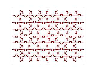
The first picture is the output of my POV file after I relearned how to use
splines. :)
I think that given a simple grid of endpoints, I can manage to play around with
the form of what's between them - and even shift the endpoints around a bit so
they're not all aligned in a rectangular grid.
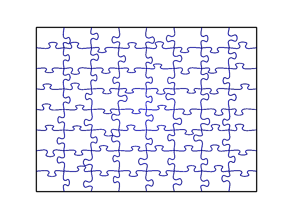
What I'm really trying to grasp is the logic by which to "split" one of those
corners in the middle of the puzzle. If you look, there are a pair of corners -
separated either vertically or horizontally, where in my grid there is only one.
Perhaps this could be called a height or a width mis-match.
I just need a bit of logic to place in my column-row loop to handle these pairs
of differently connected nodes / corners / endpoints / vertices.
This gives rise to a further refinement of slanting the puzzle edge and the
locking tab to smoothly follow that angle, which shouldn't be too bad once I get
back into the swing of things.
Then I just need to come up with some kind of formula for preventing two slots
from colliding with each other if they get generated too large or too close, and
wind up constricting and cutting off that corner.
I either need to make an array and pre-populate it with coordinates and other
connectivity data, or approach the construction of the grid a slightly different
way. I currently am starting with the top left corner and drawing down, then
over, down, then over. Maybe if I go over, then up, then I can store the
coordinates of the double corners in an array so that when I get down to the
next row, that endpoint data is available.
Thanks for looking at this - it's a far less exciting POV or raytracing project
and more of a programming problem.
Current status of the pieces shown below:
Post a reply to this message
Attachments:
Download 'jigsawpuzzle.png' (86 KB)
Preview of image 'jigsawpuzzle.png'
|
|
| |
| |
|
|
From: Le Forgeron
Subject: Re: Automated creation of jigsaw puzzle pieces
Date: 12 Feb 2016 17:35:18
Message: <56be5e26@news.povray.org>
|
|
|
| |
| |
|
|
Le 12/02/2016 17:50, Bald Eagle a écrit :
> This gives rise to a further refinement of slanting the puzzle edge and
the
> locking tab to smoothly follow that angle, which shouldn't be too bad o
nce I get
> back into the swing of things.
>
> Then I just need to come up with some kind of formula for preventing tw
o slots
> from colliding with each other if they get generated too large or too c
lose, and
> wind up constricting and cutting off that corner.
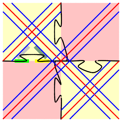
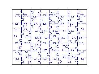
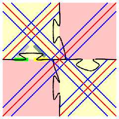
I hope you want something like the attached picture (well, if I got it
right).
The pattern is using 2 exclusive zones, with security margin to avoid
problem.
Everything with a cubic_spline (and sphere_sweep).
cubic spline is required for: smoothness and going via the point.
In the triangular area, there is at least 4 points (but a fifth can be
added). the first point must be somewhere in the green part.
the second point is along an offset diagonal, and so is the third point.
an intermediate point between second and third can be added, as long as
it is between these points on the green-yellow axis, and nearer the
centre of the tile (without entering the no-go zone of blue diagonal.
the last point is back on the axis, somewhere in the yellow line.
then we can reach the corner point.
For a non-offset cross, this is all that is needed.
For an offset cross, as done by the vertical line, we need more points:
* on the horizontal line, we need to be sure that the line is flat for
the segment inside the small diamond at the centre, so we need an
intermediate point after the yellow zone, and before the corner point,
possibly near the intersection with the blue line and the horizontal
when entering the diamond.
* on the vertical line, we need to negotiate a corner with the spline,
so even more points are needed, including one very near another just
before reaching the horizontal segment (cubic spline has a small memory,
so we need to make it forget a bit of it when joining the horizontal
segment)
That's for one crossing, it can obviously be used alternatively for the
vertical and horizontal offset on a regular grid.
Also attached the scene for it.
Post a reply to this message
Attachments:
Download 'puzzle.png' (34 KB)
Download 'puzzle.pov.txt' (3 KB)
Preview of image 'puzzle.png'
|
|
| |
| |
|
|
|
|
| |
| |
|
|
Le_Forgeron <jgr### [at] freefr> wrote:
> Le 12/02/2016 17:50, Bald Eagle a écrit :
>
> > This gives rise to a further refinement of slanting the puzzle edge and
> the
> > locking tab to smoothly follow that angle, which shouldn't be too bad o
> nce I get
> > back into the swing of things.
> >
> > Then I just need to come up with some kind of formula for preventing tw
> o slots
> > from colliding with each other if they get generated too large or too c
> lose, and
> > wind up constricting and cutting off that corner.
>
> I hope you want something like the attached picture (well, if I got it
> right).
>
> The pattern is using 2 exclusive zones, with security margin to avoid
> problem.
>
> Everything with a cubic_spline (and sphere_sweep).
>
> cubic spline is required for: smoothness and going via the point.
>
> In the triangular area, there is at least 4 points (but a fifth can be
> added). the first point must be somewhere in the green part.
> the second point is along an offset diagonal, and so is the third point.
> an intermediate point between second and third can be added, as long as
> it is between these points on the green-yellow axis, and nearer the
> centre of the tile (without entering the no-go zone of blue diagonal.
> the last point is back on the axis, somewhere in the yellow line.
> then we can reach the corner point.
>
> For a non-offset cross, this is all that is needed.
>
> For an offset cross, as done by the vertical line, we need more points:
> * on the horizontal line, we need to be sure that the line is flat for
> the segment inside the small diamond at the centre, so we need an
> intermediate point after the yellow zone, and before the corner point,
> possibly near the intersection with the blue line and the horizontal
> when entering the diamond.
> * on the vertical line, we need to negotiate a corner with the spline,
> so even more points are needed, including one very near another just
> before reaching the horizontal segment (cubic spline has a small memory,
> so we need to make it forget a bit of it when joining the horizontal
> segment)
>
> That's for one crossing, it can obviously be used alternatively for the
> vertical and horizontal offset on a regular grid.
>
> Also attached the scene for it.
another option I hadn't thought of earlier would be to populate the interior of
the area you're cutting into pieces with rectangular regions of varying
dimensions (within a certain range) and then "Connecting the dots" with some
amount of turbulence
A rule could be applied that any interior edge over a certain length has to have
a tongue or notch.
If you limit the minimum perimeter of a given region, edges below that length
can be assumed to be an offset cross.
Regards,
A.D.B
Post a reply to this message
|
|
| |
| |
|
|
|
|
| |
| |
|
|
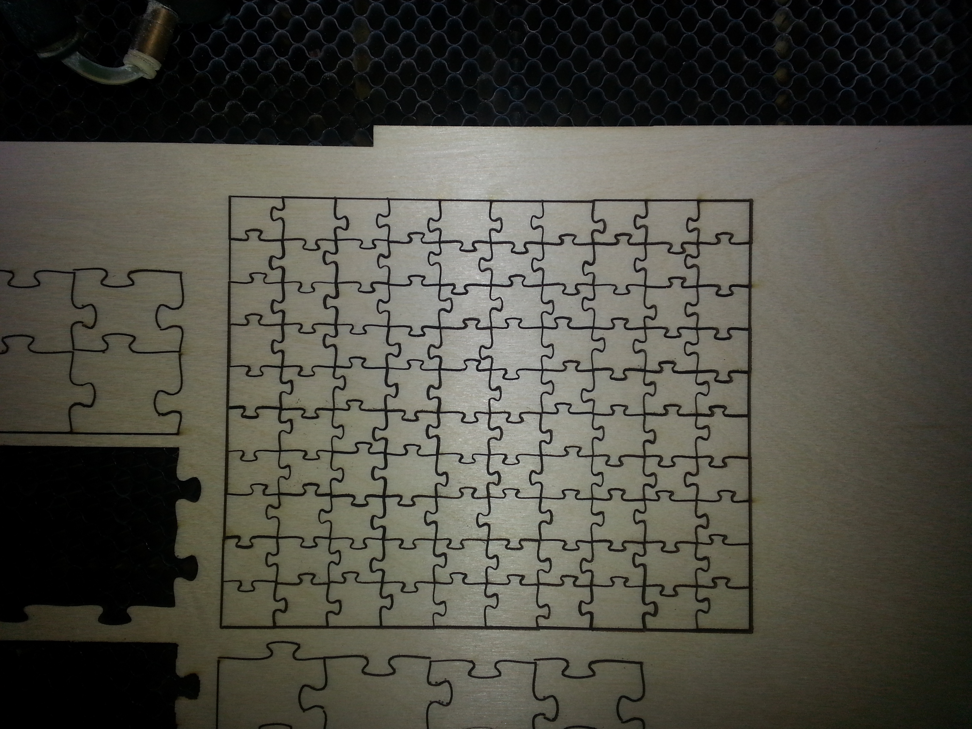
Just posting this here to show the results of some tests.
Still lots of work needed, but the overall concept works out ok.
Post a reply to this message
Attachments:
Download 'lasercutjigsaw.jpg' (2239 KB)
Preview of image 'lasercutjigsaw.jpg'

|
|
| |
| |
|
|
|
|
| |
|
|